

Page 1

Foreword
Your INFINITI represents a new way of
thinking about vehicle design. It integrates advanced engineering and superior
craftsmanship with a simple, refined aesthetic sensitivity associated with traditional Japanese culture.
The result is a different notion of luxury
and beauty. The car itself is important, but
so is the sense of harmony that thevehicle
evokes in its driver, and the sense of satisfaction you feel with the INFINITI — from
the way itlooks anddrives to thehigh level
of dealer service.
To ensure that you enjoy your INFINITI to
the fullest, we encourage you to read this
Owner’s Manual immediately. It explains
all of the features, controls and performance characteristics of your INFINITI; it
also provides important instructions and
safety information.
A separate Warranty Information Booklet
can be found in your Owner’s literature
portfolio. The INFINITI Service and Maintenance Guide explains details about
maintaining and servicingyour vehicle.Always carry it with you when you take your
INFINITI to an authorized dealer. The
portfolio contents provide complete information about all warranties covering this
vehicle, the periodic maintenance required to keep the warranties in effect as
well as the INFINITI Roadside Assistance
program.
Additionally, a separate Customer Care
and Lemon Law Information Booklet will
explain how to resolve any concerns you
may have with your vehicle, as well as
clarify your rights under your state’s
lemon law.
INFINITI is dedicated to providing a satisfying ownership experience for as long as
you own your car. Should you have any
questions regarding your INFINITI or an
INFINITI dealer, please contact our Consumer Affairs department at:
In U.S. 1-800-662-6200
In Canada 1-800-361-4792
READ FIRST — THEN DRIVE SAFELY
Before driving your vehicle please read
your Owner’s Manual carefully. This will
ensure familiarity with controls and maintenance requirements, assisting you in
the safe operation of your vehicle.
WARNING
IMPORTANT SAFETY INFORMATION
REMINDERS FOR SAFETY!
Follow these important driving rules to help
ensure a safe andcomfortable trip foryou and
your passengers!
O NEVER drive under the influence of al-
cohol or drugs.
O ALWAYS observe posted speed limits and
never drive too fast for conditions.
O
ALWAYS use your seat beltsand appropriate
child restraint systems. Preteen children
should be seated in the rear seat.
O ALWAYS provide information about the
proper use of vehicle safety features to all
occupants of the vehicle.
O ALWAYS review this Owner’s Manual for im-
portant safety information.
MODIFICATION OF YOUR VEHICLE
This vehicle should notbe modified. Modification could affect its performance,
safety or durability, and may even violate
governmental regulations. In addition,
damage or performance problems resulting from modifications may not be
covered under INFINITI warranties.
Page 2
WHEN READING THE MANUAL
This manual includes information for all
options available on this model. Therefore, you may find some information that
does not apply to your vehicle.
All information, specifications and illustrations in this manual are those in effect at
the time of printing. INFINITI reserves the
right to change specifications or design at
any time without notice.
IMPORTANT INFORMATION ABOUT
THIS MANUAL
You will see various symbols in this manual.
They are used in the following ways:
WARNING
This is used to indicate the presence of a hazard that could cause death or serious personal injury. To avoid or reduce the risk, the
procedures must be followed precisely.
SIC0697
If you see this symbol, it means Do not do
this or Do not let this happen.
If you see a symbol similar to these in an
illustration, it means the arrow points to
the front of the vehicle.
CALIFORNIA PROPOSITION 65
WARNING
WARNING
Engine exhaust, some of its constituents, and
certain vehicle components contain or emit
chemicals known to the State of California to
cause cancer and birth defects or other reproductive harm. In addition, certain fluids contained in vehicles and certain products of
component wear contain or emit chemicals
known to the State of California to cause cancer and birth defects or other reproductive
harm.
BLUETOOTH is a trademark
owned by Bluetooth SIG,
Inc., U.S.A. and licenced to
Xanavi Informatics Corporation.
CAUTION
This is used to indicate the presence of a hazard that could cause minor or moderate personal injury or damage to your vehicle. To
avoid or reduce the risk, the procedures must
be followed carefully.
Arrows in an illustration that are similar to
these indicate movement or action.
Arrows in an illustration that are similar to
these call attention to an item in the illustration.
© 2005 NISSAN MOTOR CO., LTD.
All rights reserved. No part ofthis Owner’s Manual maybe
reproduced or stored in a retrieval system, or transmitted
in any form, orby anymeans, electronic,mechanical, photocopying, recording or otherwise, without the prior
written permission of Nissan Motor Co., Ltd.
TOKYO, JAPAN
Page 3

Table of
Illustrated table of contents
0
Contents
Safety — Seats, seat belts and supplemental restraint system
Instruments and controls
Pre-driving checks and adjustments
Display screen, heater, air conditioner and audio systems
Starting and driving
In case of emergency
Appearance and care
Maintenance and do-it-yourself
Technical and consumer information
Index
1
2
3
4
5
6
7
8
9
10
Page 4

Page 5

0 Illustrated table of contents
Exterior ............................................................ 0-2
Instrument panel.............................................. 0-3
Meters and gauges ........................................... 0-4
Engine compartment......................................... 0-5
VQ35DE engine ........................................... 0-5
VK45DE engine ........................................... 0-6
Page 6
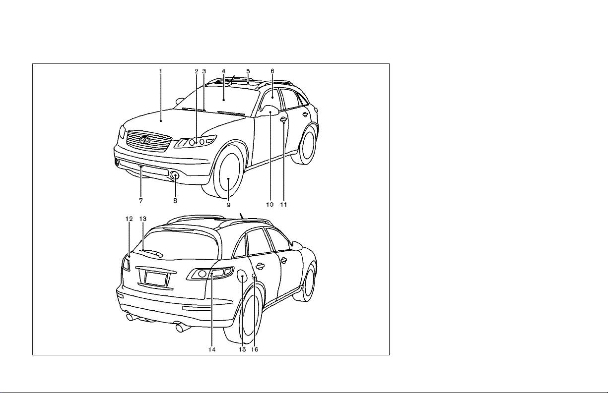
EXTERIOR
1. Hood (Page 3-24)
2. Headlight and turn signal switch
(P.2-21)
3. Wiper and washer switch (P.2-21)
4. Windshield (P.8-21)
5. Sunroof (if so equipped) (P.2-43)
6. Power windows (P.2-41)
7. Recovery hook (P.6-16)
8. Fog light and switch (P.2-28)
9. Tires
— Wheel and tires (P.8-35, 9-10)
— Flat tire (P.6-2)
10. Mirrors (P.3-30)
11. Doors (P.3-3)
— Keys
— Door locks
— Remote keyless entry system
— Intelligent Key (if so equipped)
12. Lift gate (P.3-24)
13. Rear window wiper (P.8-23)
14. Rear combination light (P.8-33)
15. Fuel-filler door (P.3-26)
16. Child safety locks (P.3-5)
0-2 Illustrated table of contents
SSI0012A
Page 7
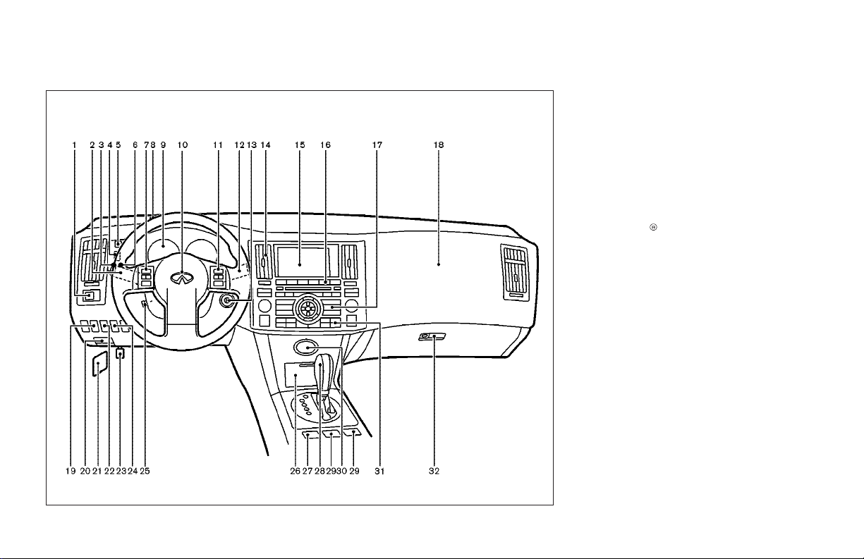
INSTRUMENT PANEL
SSI0182
1. Outside mirror remote control (P.3-31)
2. Headlight, fog light and turn signal
switch (P.2-23)
3. Trip odometer reset knob (P.2-4)
4. Instrument brightness control switch
(P.2-25)
5. Headlight aiming control switch
(P.2-26)
6. Trip odometer select knob (P.2-4)
7. Steering switch for Audio (P.4-40)/
Bluetooth
(if so equipped) (P.4-41)
8. Security indicator light (P.2-18)
9. Meters and gauges (P.2-3)
10. Driver supplemental air bag (P.1-37)
11. Cruise control main/set switch
(P.5-22) or Intelligent cruise control
switch (if so equipped) (P.5-24)
12. Windshield wiper/washer switch
(P.2-21)
13. Ignition switch (P.3-14)
14. Center ventilator (P.4-20)
15. Display (P.4-4)/Navigation system (if
so equipped)*
16. Audio system (P.4-25)
17. Center multi-function control panel
(P.4-2)
18. Front passenger supplemental air bag
(P.1-37)
Hands-Free Phone System
Illustrated table of contents 0-3
Page 8
19. Lane departure warning (LDW) switch
(if so equipped) (P.2-30)
20. Hood release handle (P.3-24)
21. Fuse box (P.8-24)
22. SNOW mode switch (P.2-31)
23. Parking brake (P.5-18)
24. Vehicle dynamic control (VDC) OFF
switch (P.2-31)
25. Tilting/telescopic steering wheel
switch (P.3-28)
26. Storage box and power outlet (P.2-33,
P.2-35)
27. Hazard warning flasher switch
(P.2-28)
28. Automatic transmission selector lever
(P.5-14)
29. Heated seat switch (P.2-29)
30. Clock (P.2-32)
31. Automatic climate control system
(P.4-21)
32. Glove box (P.2-36)
*: Refer to the separate Navigation System
Owner’s Manual. (if so equipped)
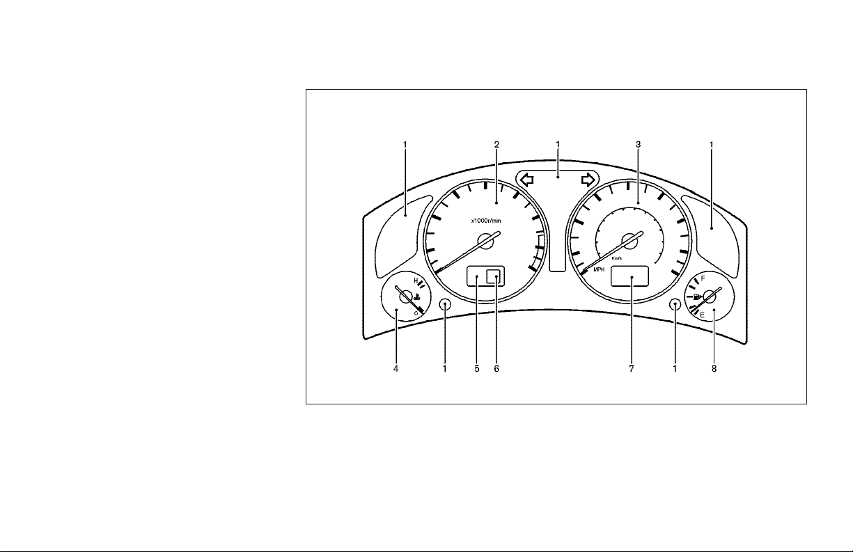
METERS AND GAUGES
SIC2135
0-4 Illustrated table of contents
1. Warning/Indicator lights (P.2-9)
2. Tachometer (P.2-4)
3. Speedometer (P.2-4)
4. Engine coolant temperature gauge
(P.2-5)
5. Intelligent cruise control system display (if so equipped) (P.5-24)
6. Automatic transmission position indicator (P.5-14)
7. Odometer (Total/Twin trip) (P.2-4)
8. Fuel gauge (P.2-5)
Page 9
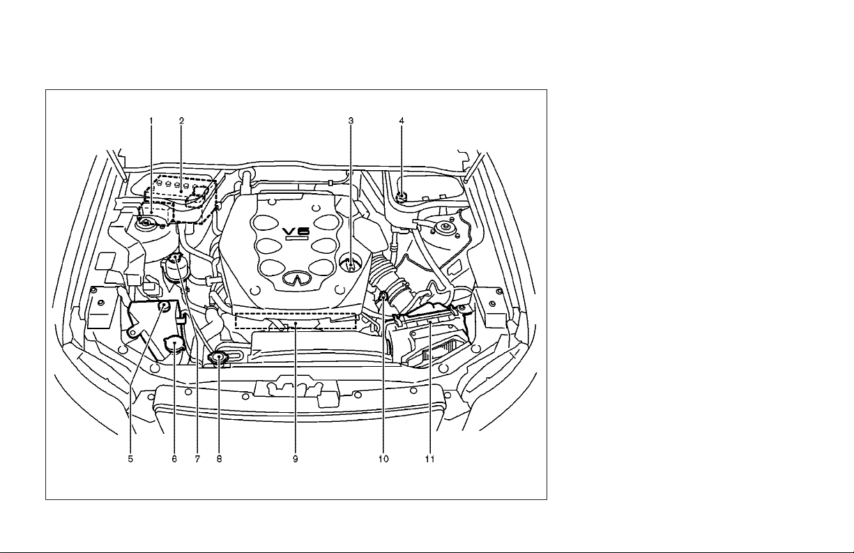
ENGINE COMPARTMENT
VQ35DE ENGINE
1. Fuse/fusible link holder (P.8-24)
2. Battery (P.8-17)
3. Engine oil filler cap (P.8-11)
4. Brake fluid reservoir (P.8-16)
5. Engine coolant reservoir (P.8-9)
6. Window washer fluid reservoir
(P.8-16)
7. Power steering fluid reservoir (P.8-15)
8. Radiator filler cap (P.8-9)
9. Drive belts (P.8-19)
10. Engine oil dipstick (P.8-11)
11. Air cleaner (P.8-20)
SDI1991
Illustrated table of contents 0-5
Page 10
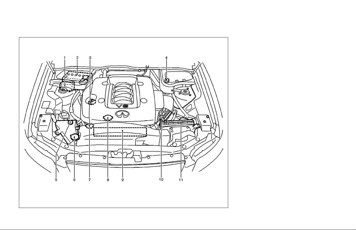
0-6 Illustrated table of contents
VK45DE ENGINE
1. Fuse/fusible link holder (P.8-24)
2. Battery (P.8-17)
3. Engine oil filler cap (P.8-11)
4. Brake fluid reservoir (P.8-16)
5. Engine coolant reservoir (P.8-9)
6. Window washer fluid reservoir
(P.8-16)
7. Power steering fluid reservoir (P.8-15)
8. Radiator filler cap (P.8-9)
9. Drive belts (P.8-19)
10. Engine oil dipstick (P.8-11)
11. Air cleaner (P.8-20)
SDI1987
Page 11

1
Safety — Seats, seat belts and supplemental
restraint system
Seats................................................................ 1-2
Front power seat adjustment........................ 1-2
Rear seat adjustment................................... 1-4
Head restraint adjustment ........................... 1-6
Active head restraint (front seats)................. 1-7
Armrest....................................................... 1-7
Seat belts......................................................... 1-8
Precautions on seat belt usage .................... 1-8
Child safety............................................... 1-11
Pregnant women ....................................... 1-12
Injured persons......................................... 1-12
Three-point type seat belt with retractor ..... 1-12
Rear center seat belt.................................. 1-15
Seat belt extenders.................................... 1-18
Seat belt maintenance............................... 1-18
Child restraints............................................... 1-19
Precautions on child restraints................... 1-19
Child restraint installation on rear seat
outboard or center positions...................... 1-21
LATCH (Lower Anchors and Tethers for
CHildren) system ....................................... 1-26
Top tether strap child restraint................... 1-27
Child restraint installation on front
passenger seat.......................................... 1-29
Booster seats ................................................. 1-32
Precautions on booster seats..................... 1-32
Booster seat installation on rear seat
outboard or center positions...................... 1-35
Booster seat installation on front
passenger seat.......................................... 1-36
Supplemental restraint system........................ 1-37
Precautions on supplemental restraint
system...................................................... 1-37
INFINITI advanced air bag system
(front seats)............................................... 1-43
Supplemental air bag warning labels.......... 1-51
Supplemental air bag warning light............ 1-52
Page 12
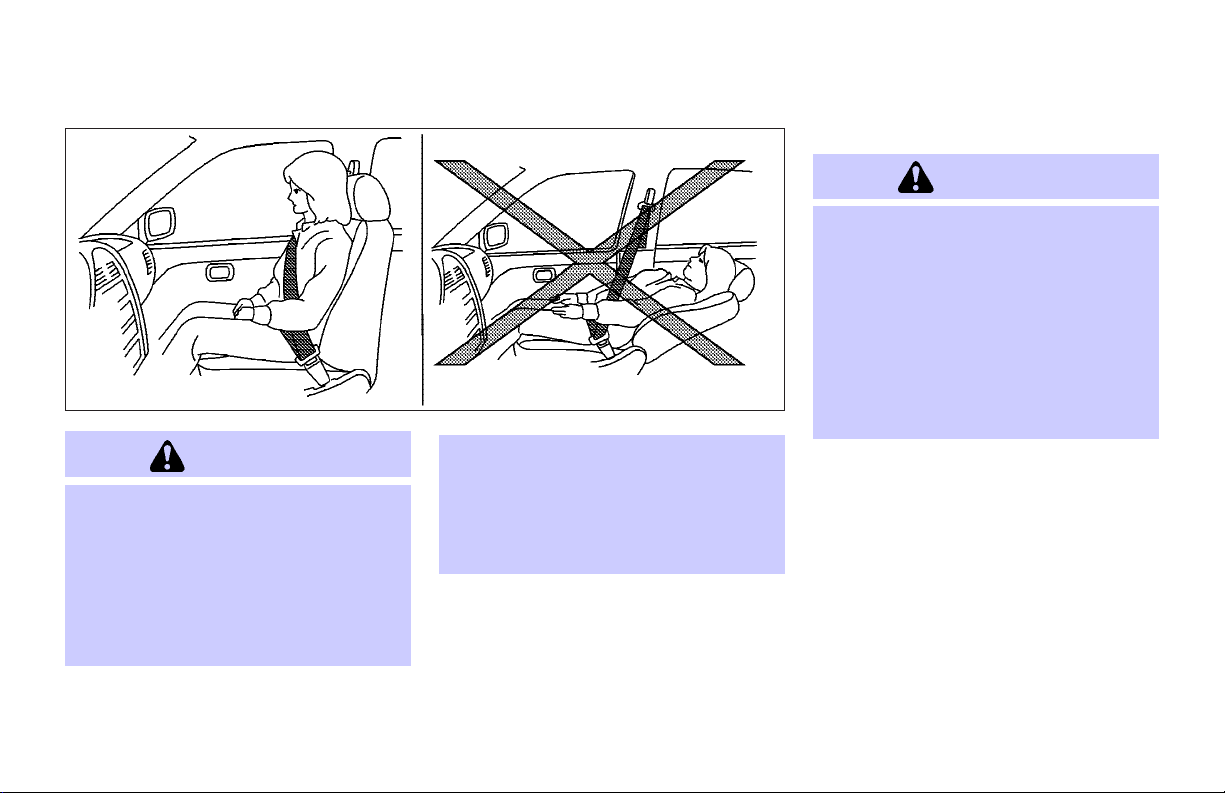
SEATS
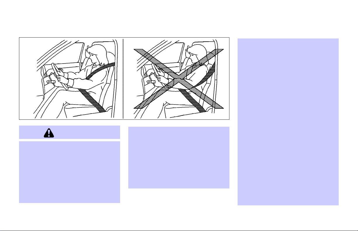
WARNING
O Do not ride in a moving vehicle when the
seatback is reclined. This can be dangerous. The shoulder belt will not be
against your body. In an accident, you
could be thrown into it and receive neck
or other serious injuries. You could also
slide under the lap belt and receive serious internal injuries.
O For the most effective protection when
the vehicle is in motion, the seat should
be upright. Always sit well back in the
seat and adjust the seat belt properly.
See “Precautions on seat belt usage”
later in this section.
1-2 Safety — Seats, seat belts and supplemental restraint system
SSS0133B
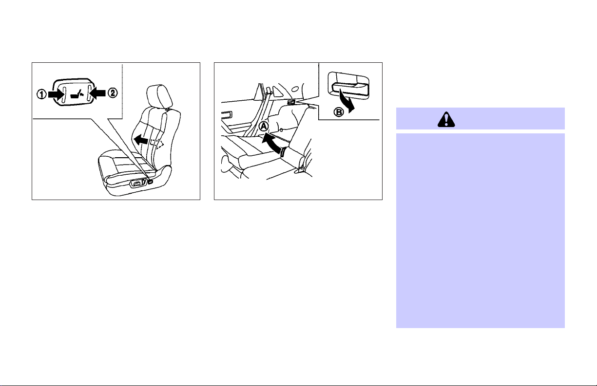
FRONT POWER SEAT ADJUSTMENT
WARNING
O Do not adjust thedriver’s seat whiledriv-
ing so full attention may be given to vehicle operation. The seat may move suddenly and could cause loss of control of
the vehicle.
O Do not leave children unattended inside
the vehicle. They could unknowingly activate switches or controls. Unattended
children could become involved in serious accidents.
Operating tips
O The seat motor has an auto-reset over-
load protection circuit. If the motor
stops during operation, wait 30 seconds, then reactivate the switch.
O Do not operate the power support seat
for a long period of time when the engine is off. This will discharge the battery.
See “Automatic drive positioner” in the “3.
Pre-driving checks and adjustments” section for automatic drive positioner operation.
Page 13
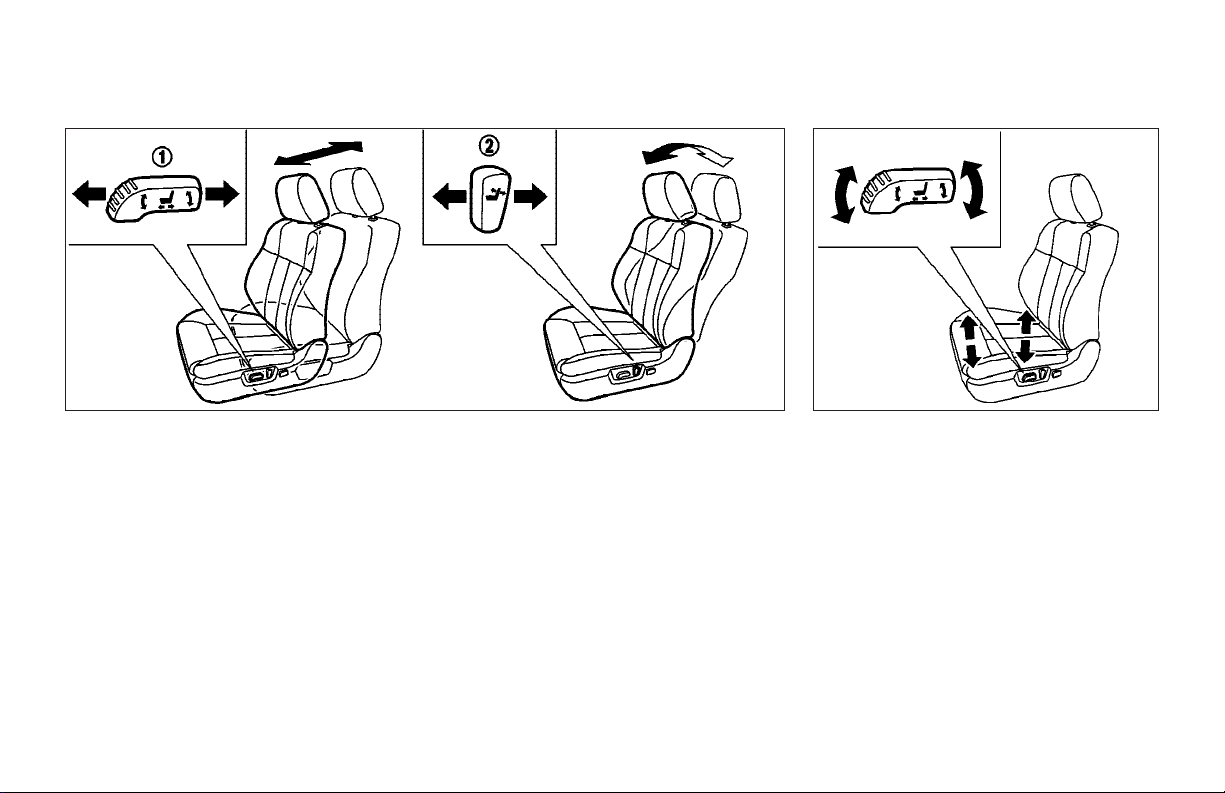
SSS0474 SSS0475
Forward and backward
Moving the switch
will slide the seat forward or backward to
the desired position.
1
forward or backward
j
Reclining
Move the recline switch
the desired angle is obtained. To bring the
seatback forward again, move the switch
2
forward.
j
The reclining feature allows adjustment of
the seatback for occupants of different
sizes for added comfort and to help obtain
proper seat belt fit. See “Precautions on
seat belt usage” later in this section. The
seatback may be reclined to allow occupants to rest when the vehicle is parked.
2
backward until
j
Safety — Seats, seat belts and supplemental restraint system 1-3
Seat lifter
Push the front or rear end of the switch up
or down to adjust the height and angle of
the seat.
For the front passenger’s seat, only the
angle of the seat can be adjusted.
Page 14
SSS0476 SSS0247
Lumbar support (if so equipped for
driver’s seat)
The lumbar support feature provides lower
back support to the driver. Push the front
1
or back
j
the seat lumbar area.
2
end of the switch to adjust
j
REAR SEAT ADJUSTMENT
Folding
1. Store the center seat belts in the proper
position. (See “REAR CENTER SEAT
BELT” later in this section.)
2. Slide the front seat forward if necessary. (See “FRONT POWER SEAT ADJUSTMENT” earlier in this section.)
3. Pull the seat belt to side.
4. After removing the tonneau cover (if so
equipped), pull the lever on the rear
A
seat
j
or pull thelever on bothsides of
1-4 Safety — Seats, seat belts and supplemental restraint system
B
j
the luggage room
back.
5. When resetting the seat, be sure to install the head restraints.
and fold the seat-
WARNING
O Never allow anyone to ride in the cargo
area or on the rear seat when it is in the
fold-down position. Use of these areas
by passengers without proper restraints
could result in serious injury in an accident or sudden stop.
O It is extremely dangerous to ride in a
cargo area inside avehicle. Ina collision,
people riding in these areas are more
likely to be seriously injured or killed.
O Do not allow people to ride in any area of
your vehicle that is not equipped with
seats and seat belts. Be sure everyone in
your vehicle is in a seat and using a seat
belt properly.
O Do not fold down the rear seats when oc-
cupants are in the rear seat area, any
Page 15

luggage is on the rear seat or any cup is
in the cup holder.
O Head restraints should be adjustedprop-
erly as they may provide significant protection against injury in an accident. Always replace and adjust them properly if
they have been removed for any reason.
O If the head restraints are removed for
any reason, they should be securely
stored to prevent them from causing injury to passengers or damage to the vehicle in case of sudden braking or an accident.
O Properly secure all cargo to help prevent
it from sliding or shifting. Do not place
cargo higher than the seatbacks. In a
sudden stop or collision, unsecured
cargo could cause personal injury.
O When returning the seatbacks to the up-
right position, be certain they are completely securedin thelatched position.If
they are notcompletely secured, passengers maybe injured in anaccident orsudden stop.
O When returning theseatbacks,be sure to
attach the rear center seat belt connector.
O Do not unfasten the rear center seat belt
connector except when folding down the
rear seat.
O When attaching the rear center seat belt
connector, be certain that the seatbacks
are completelysecured inthe latchedposition and the rear center seat belt connector is completely secured.
O If the rear center seat belt connector and
the seatbacks are not secured in the correct position, serious personal injury
may result in an accident or sudden stop.
SSS0248
Reclining
Pull the reclining lever
seat back at the desired angle
the reclining lever
seat at the desired angle
1
and position the
j
1
after positioning the
j
j
2
. Release
j
2
.
WARNING
O Do not ride in a moving vehicle when the
seatback is reclined. This can be dangerous. The shoulder belt will not be
against your body. In an accident,
Safety — Seats, seat belts and supplemental restraint system 1-5
Page 16
you could be thrown into it and receive
neck or other serious injuries. You could
also slide under the lap belt and receive
serious internal injuries.
O For the most effective protection when
the vehicle is in motion, the seat should
be upright. Always sit well back in the
seat and adjust the seat belt properly.
See “Precautions on seat belt usage”
later in this section.
O After adjustment, gently rock in the seat
to make sure it is securelylocked.
SSS0125C SSS0287
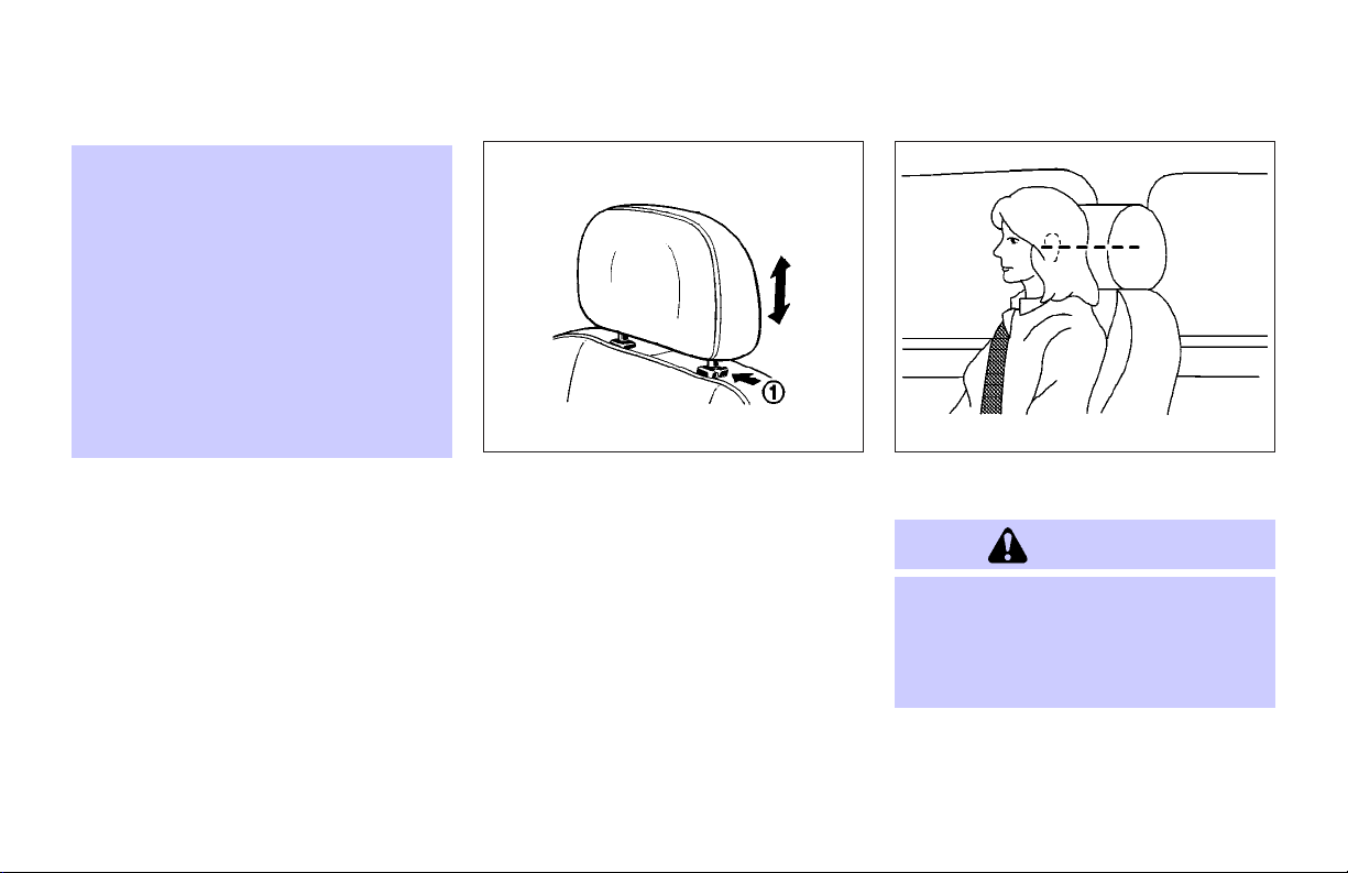
HEAD RESTRAINT ADJUSTMENT
To raise the head restraint, just pull it up.
To lower, push the lock knob
the head restraint down.
1-6 Safety — Seats, seat belts and supplemental restraint system
1
and push
j
Adjust the head restraints so the center is
level with the center of your ears.
WARNING
Head restraints should be adjusted properly
as they may provide significant protection
against injury in an accident. Do not remove
them. Check the adjustment after someone
else uses the seat.
Page 17
SSS0508 SSS0596
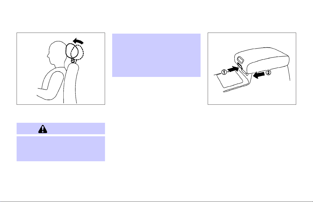
ACTIVE HEAD RESTRAINT (front
seats)
WARNING
O Always adjust the head restraints prop-
erly as specified in the previous section.
Failure to do so can reduce the effectiveness of the active head restraint.
O Active head restraints are designed to
supplement other safety systems. Always wear seat belts. No system canprevent all injuries in any accident.
O Do not attach anything to the head re-
straint stalks. Doing so could impair active head restraint function.
The active head restraint moves forward
utilizing the force that the seatback receives from the occupant in a rear-end collision. The movement of the head restraint
helps support the occupant’s head by reducing its backward movement and
helping absorb some ofthe forces that may
lead to whiplash type injuries.
Active head restraints areeffective for collisions at low to medium speeds in which it
is said that whiplash injury occurs most.
Active head restraints operate only in certain rear-end collisions. After the collision,
the head restraints return to their original
positions.
Properly adjust the active head restraints
as described in the previous section.
ARMREST
Front
Front
Push the button
2
rest
To use the console box, see “Console box”
in the “2. Instruments and controls” section.
to the desired position.
j
1
while sliding the arm-
j
Safety — Seats, seat belts and supplemental restraint system 1-7
Page 18
SEAT BELTS
PRECAUTIONS ON SEAT BELT
USAGE
If you are wearing your seat belt properly
adjusted, and you are sitting upright and
well back in your seat, your chances of
being injured or killed in an accident
and/or the severity of injury may be greatly
reduced. INFINITI strongly encourages
you and all ofyour passengers to buckleup
every time you drive, even if your seating
position includes a supplemental air bag.
Most states, provinces or territories require that seat belts be worn at all times
when a vehicle is being driven.
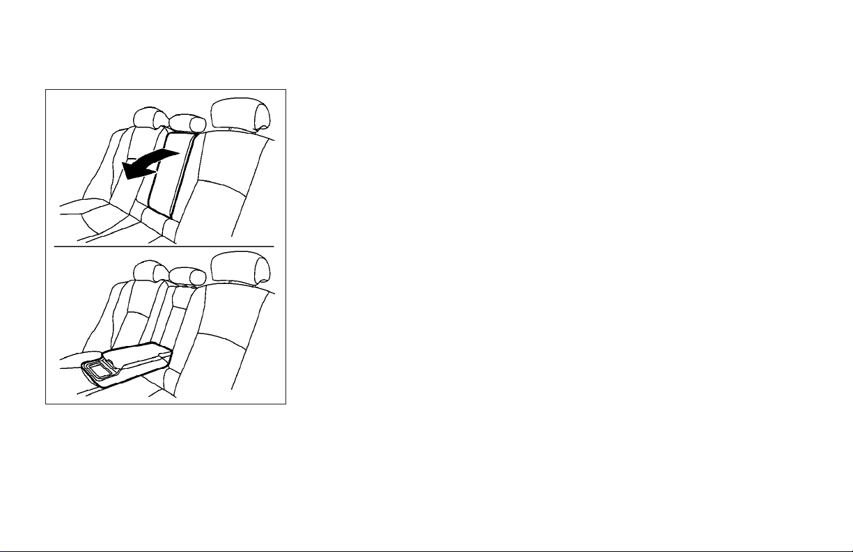
Rear
SSS0243
Rear
Pull the armrest forward until it is horizontal.
1-8 Safety — Seats, seat belts and supplemental restraint system
Page 19
WARNING
O Every person who drives or rides in this
vehicle should use a seat belt at all
times. Children should be properly restrained in the rear seat and, if appropriate, in a child restraint.
O The seat belt should be properly ad-
justed to a snug fit. Failure to do so may
reduce the effectiveness of the entire restraint system and increase the chance
SSS0136A
or severity of injury in an accident. Serious injury or death can occur if the seat
belt is not worn properly.
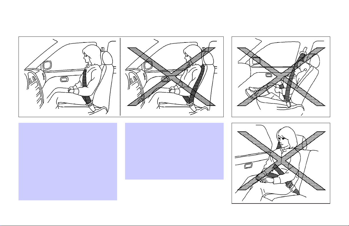
O Always route the shoulder belt over your
shoulder and across your chest. Never
run the beltbehind your back, under your
arm or across your neck. The belt should
be away from your face and neck, but not
falling off your shoulder.
O Position the lap belt as low and snug as
possible AROUND THE HIPS, NOT THE
WAIST. A lap belt worn too high couldincrease the risk of internal injuries in an
accident.
O Be sure the seat belt tongue is securely
fastened to the proper buckle.
O Do not wear the seat belt inside out or
twisted. Doing so may reduce its effectiveness.
O Do not allow more than one person to
use the same seat belt.
O Never carry more people in the vehicle
than there are seat belts.
O If the seat belt warning light glows con-
tinuously while the ignition is turned ON
with all doors closed and all seat belts
fastened, itmay indicate a malfunctionin
the system. Have the system checked by
an INFINITI dealer.
O Once thepre-tensionerseat belthasacti-
vated, it cannot be reused and must be
replaced together with the retractor. See
an INFINITI dealer.
Safety — Seats, seat belts and supplemental restraint system 1-9
Page 20
SSS0134A SSS0016
O Removal and installation of the pre-
tensioner seat belt system components
should be done by an INFINITI dealer.
O All seat belt assemblies, including re-
tractors and attaching hardware, should
be inspected after any collision by an
INFINITI dealer. INFINITI recommends
that all seat belt assemblies in use
during a collision be replaced unless the
spected and replaced if either damageor
improper operation is noted.
O All child restraints and attaching hard-
ware should be inspected after any collision. Always follow the restraint manufacturer’s inspection instructions and replacement recommendations. The child
restraints should be replaced if they are
damaged.
collision was minor and the belts show
no damage and continue to operate
properly. Seat belt assemblies notin use
during a collision should also be in-
1-10 Safety — Seats, seat belts and supplemental restraint system
SSS0014
Page 21

CHILD SAFETY
Children need adults to help protect them.
They need to be properly restrained.
In addition to the general information in
this manual, child safety information is
available from many other sources, including doctors, teachers, government
traffic safety offices, and community organizations. Every child is different, so be
sure to learn the best way to transport your
child.
There are three basic types of child restraint systems:
O Rear facing child restraint
O Front facing child restraint
O Booster seat
The proper restraint depends on the child’s
size. Generally, infants (up to about 1 year
and less than 20 lb (9 kg)) should be
placed in rear facing child restraints. Front
facing child restraints areavailable for children who outgrow rear facing child restraints and are at least 1 year old. Booster
seats are used to help position a vehicle
lap/shoulder belt on a child who can no
longer use a front facing child restraint.
WARNING
Infants and children need special protection.
The vehicle’s seat belts may not fit them
properly. The shoulder belt may come too
close to the face or neck. The lap belt may
not fit over their small hip bones. In an accident, an improperly fitting seat belt could
cause serious or fatal injury. Always use appropriate child restraints.
All U.S. states and Canadian provinces or
territories require the use of approved
child restraints for infants and small children. (See “Child restraints” later in this
section.)
Also, there are other types of child restraints available for larger children for additional protection.
INFINITI recommends that all pre-teens
and children be restrained in the rear seat.
According to accident statistics, children
are safer when properly restrained in the
rear seat than in the front seat.
This is especially important because your
vehicle has a supplemental restraint
Safety — Seats, seat belts and supplemental restraint system 1-11
system (air bag system) for the front passenger. See “Supplemental restraint
system” later in this section.
Infants
Infants up to at least one year old should
be placed in a rear facing child restraint.
INFINITI recommends that infants be
placed in child restraints that comply with
Federal Motor Vehicle Safety Standards or
Canadian Motor Vehicle Safety Standards.
You should choose a child restraint which
fits your vehicle and always follow the
manufacturer’s instructions for installation
and use.
Small children
Children that are over one year old and
weigh between 20 lb (9 kg) and 40 lb (18
kg) can be placed in a forward facing child
restraint. Refer to the manufacturer’s instructions for minimum and maximum
weight and height recommendations. INFINITI recommends that small children be
placed in child restraints that comply with
Federal Motor Vehicle Safety Standards or
Canadian Motor Vehicle Safety Standards.
You should choosea child restraintthat fits
your vehicle and always follow the manufacturer’s instructions for installation and
use.
Page 22
Larger children
Children who are too large for child restraints should be seated and restrained
by the seat belts which are provided. The
seat belt may not fit properly if the child is
less than 4 feet 9 inches (142.5 cm) tall
and weighs between40 lb (18kg) and80 lb
(36 kg). A booster seat should be used to
obtain proper seat belt fit.
INFINITI recommends that a child be
placed in a commercially available booster
seat if the shoulder belt in the child’s seating position fits close to the face or neck or
if the lap portion of the seat belt goes
across the abdomen. The booster seat
should raise the child so that the shoulder
belt is properly positioned across the top,
middle portion of the shoulder and the lap
belt is low on the hips. A booster seat can
only be used in seating positions that have
a three-point type seat belt. The booster
seat should fit the vehicle seat and have a
label certifying that it complies with Federal Motor Vehicle Safety Standards or Canadian Motor Vehicle Safety Standards.
Once the child has grown so the shoulder
belt is no longer on or near the face and
neck, use the shoulder belt without the
booster seat.
WARNING
Never let a child stand or kneel on any seat
and do not allow a child in the cargo areas
while the vehicle is moving. The child could
be seriously injured or killed in an accident
or sudden stop.
PREGNANT WOMEN
INFINITI recommends that pregnant
women use seat belts. The seat belt should
be worn snug, and always position the lap
belt as lowas possible aroundthe hips, not
the waist, and place the shoulder belt over
your shoulder and across your chest.Never
run the lap/shoulder belt over your abdominal area. Contact your doctor for specific recommendations.
INJURED PERSONS
INFINITI recommends that injuredpersons
use seat belts, depending on the injury.
Check with your doctor for specific recommendations.
Front seat
SSS0292
THREE-POINT TYPE SEAT BELT WITH
RETRACTOR
WARNING
O Every person who drives or rides in this
vehicle should use a seat belt at all
times.
O Do not ride in a moving vehicle when the
seatback is reclined. This can be dangerous. The shoulder belt will not be
against your body. In an accident,
1-12 Safety — Seats, seat belts and supplemental restraint system
Page 23
Rear seat
SSS0293
you could be thrown into it and receive
neck or other serious injuries. You could
also slide under the lap belt and receive
serious internal injuries.
O For the most effective protection when
the vehicle is in motion, the seat should
be upright. Always sit well back in the
seat and adjust the seat belt properly.
Front seat
SSS0290
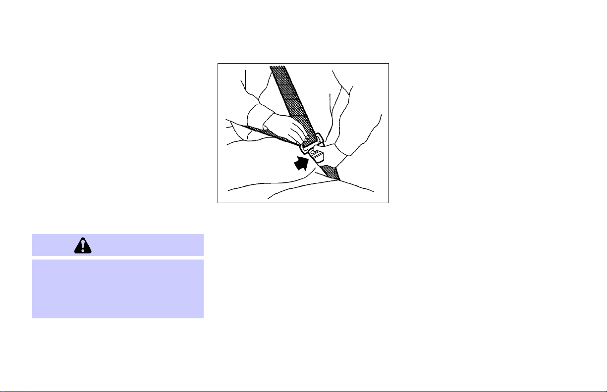
Fastening the seat belts
1. Adjust the seat. See “Seats” earlier in
this section.
2. Slowly pull the seat belt out of the retractor and insert the tongue into the
buckle until it clicks. (For additional information regarding the rear center
seat belt, see “Setting center seat
belt”.)
O The retractor is designed to lock during
a sudden stop or on impact. A slow
pulling motion will permit the belt to
move, and allow you some freedom of
movement in the seat.
Safety — Seats, seat belts and supplemental restraint system 1-13
Rear seat
SSS0291A
O If the seat belt cannot be pulled from
its fully retracted position, firmly pull
the belt and release it. Then smoothly
pull the belt out of the retractor.
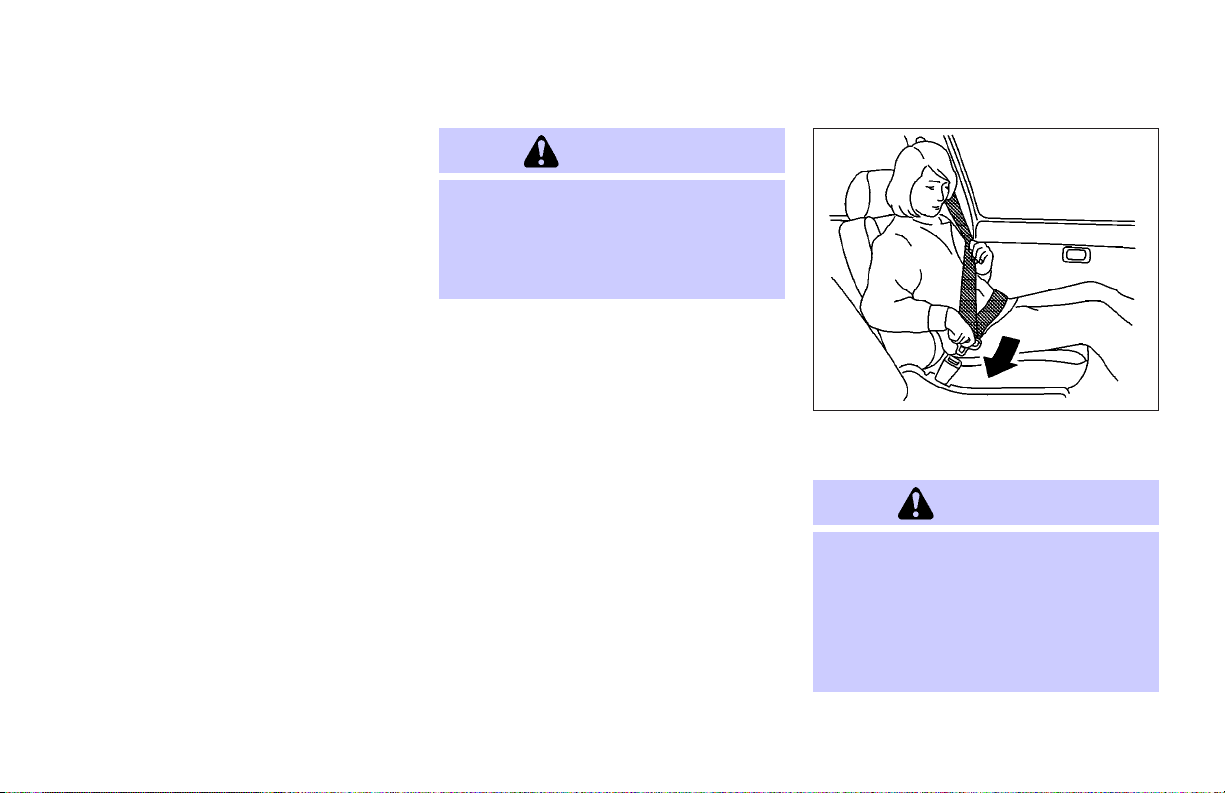
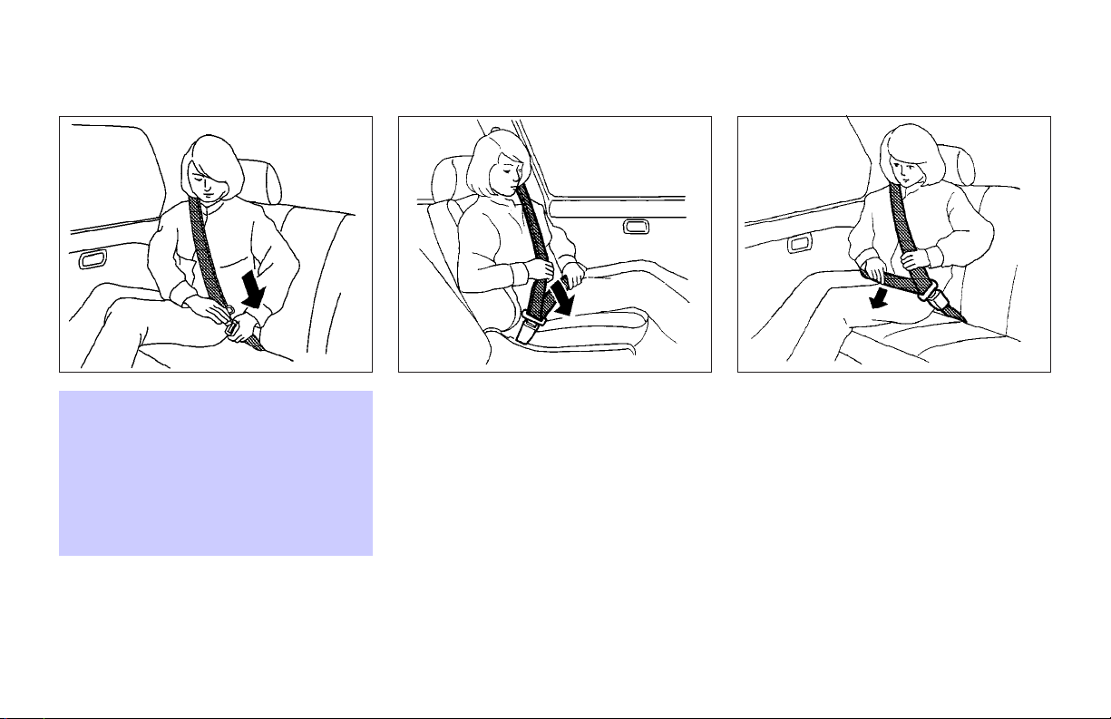
3. Position the lap belt portion low and
snug on the hips as shown.
4. Pull the shoulder belt portion toward
the retractor to take up extra slack. Be
sure the shoulder belt is routed over
your shoulder and across your chest.
The front passenger and rear seat belts
have a locking mechanism for child re-
Page 24
straint installation. It is referred to as the
automatic locking mode.
When the locking mechanism is activated
the seat belt cannot be extended again until the seat belt tongue is detached from
the buckle and fully retracted. For additional information, see “Child restraints”
later in this section.
The automatic locking mode should be
used only for child restraint installation.
During normal seat belt use by a passenger, the lockingmode should notbe activated. If it is activated it may cause uncomfortable seat belt tension. It can also
change the operation of the front passenger air bag. See “Front passenger air
bag and status light” later in this section.
WARNING
When fastening the seat belts, be certain
that the seatbacks are completely secured in
the latched position. If they are not completely secured, passengers may be injured
in an accident or sudden stop.
To increase your confidence in the seat
belts, check the operation as follows:
O grasp the shoulder belt and pull quickly
forward. The retractor should lock and
restrict further belt movement.
If the retractor does not lock during this
check or if you have any questions about
belt operation, see an INFINITI dealer.
SSS0326
Unfastening the seat belts
To unfasten the belt, press the button on
the buckle. The seat belt will automatically
retract.
Checking seat belt operation
Your seat belt retractors are designed to
lock belt movement using two separate
methods:
O when the belt is pulled quickly from the
retractor.
O when the vehicle slows down rapidly.
1-14 Safety — Seats, seat belts and supplemental restraint system
Page 25
WARNING
O After adjustment, release the adjustment
button and try to move the shoulder belt
anchor up anddown to make sure itis securely fixed in position.
O The shoulder belt anchor height should
be adjusted to the position best for you.
Failure to do so may reduce the effectiveness of the entire restraint system and
increase the chance or severity of injury
SSS0351 SSS0240
in an accident.
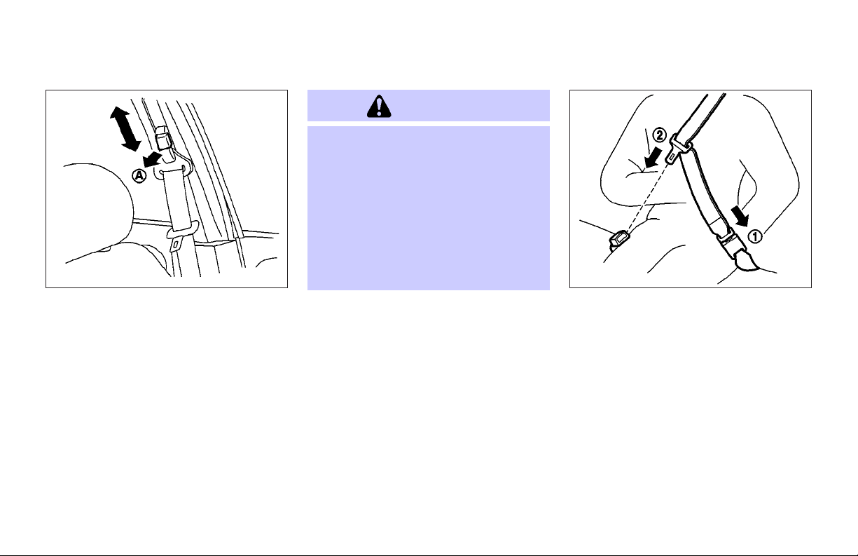
Shoulder belt height adjustment
(for front seats)
The shoulder belt anchor height should be
adjusted to the position best suited for
you. (See “Precautions on seat belt usage”
earlier in this section.) To adjust, pull the
release button
shoulder belt anchor to the desired position, so that the beltpasses over the center
of the shoulder. The belt should be away
from your face and neck, but not falling off
of your shoulder. Release the adjustment
button to lock theshoulder belt anchor into
position.
A
j
, and then move the
REAR CENTER SEAT BELT
The rear center seat belt has a connector
tongue
the connector tongue and the seat belt
tongue must be securely latched for proper
seat belt operation.
Safety — Seats, seat belts and supplemental restraint system 1-15
1
and a seat belt tongue
j
j
2
. Both
Page 26
SSS0241
WARNING
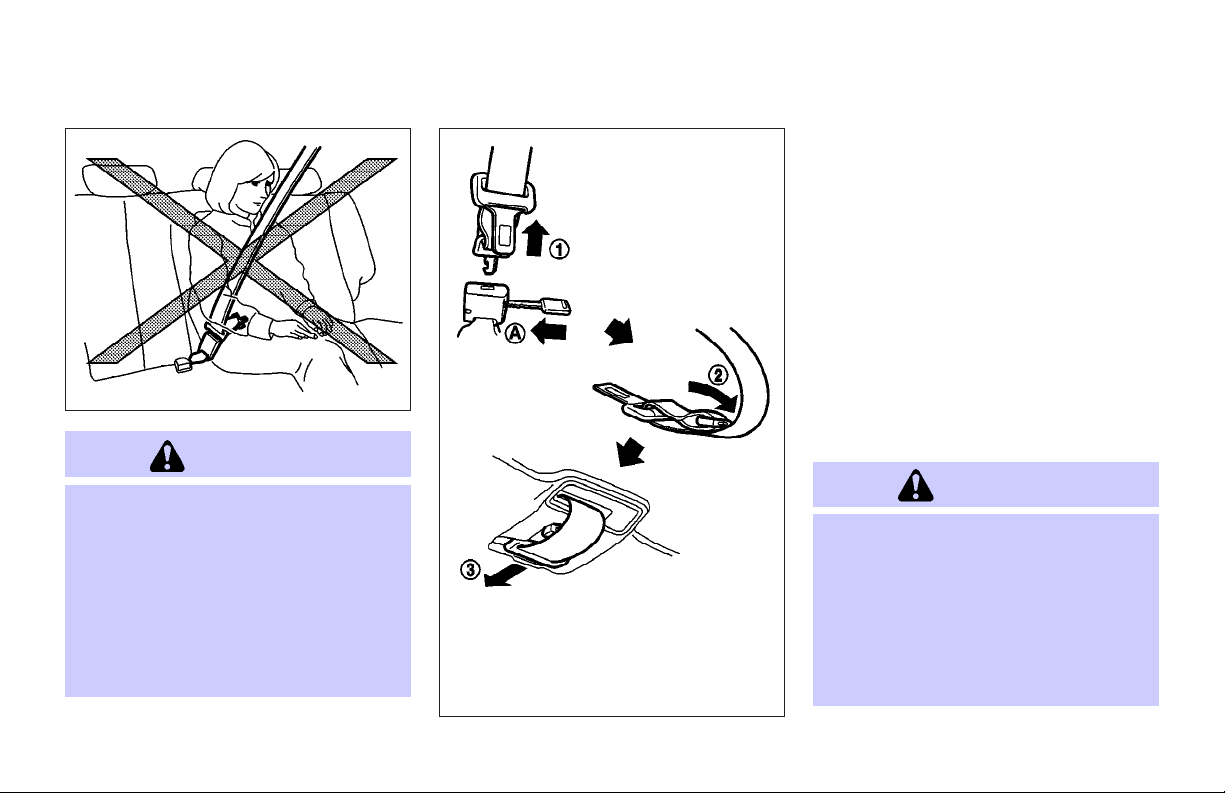
O Always fasten the connector tongue and
the seat belt in the order shown.
O Always make sure both the connector
tongue and the seat belt tongue are secured when using the seat belt. Do not
use it with only the seat belt tongue attached. This could result in serious personal injury in case of an accident or a
sudden stop.
1-16 Safety — Seats, seat belts and supplemental restraint system
SSS0249
Stowing rear center seat belt
When folding down the rear seat, the rear
center seat belt can be retracted into a
stowed position as follows:
1. Hold the connector tongue
the seat belt does not retract suddenly
when the tongue is released from the
connector buckle.
2. Insert a suitable tool such as a key
into the connector buckle and release
the connector tongue.
3. Fold the connector as illustrated
4. Then secure the connector tongue into
the retractor base
j
3
1
so that
j
in the ceiling.
j
A
j
2
.
WARNING
O Do not unfasten the rear center seat belt
connector except when folding down the
rear seat.
O When attaching the rear center seat belt
connector, be certain that the seatbacks
are completelysecured inthe latchedposition and the rear center seat belt connector is completely secured.
Page 27

O If the rear center seat belt connector and
the seatbacks are not secured in the correct position, serious personal injury
may result in an accident or sudden stop.
Attaching rear center seat belt
Always be sure the rear center seat belt
connector tongue and connectorbuckle are
attached. Disconnect only when folding
down the rear seat.
To connect the buckle:
1. Pull out the seat belt tongue from the
retractor base
2. Pull the seat belt and secure the connector buckle until it clicks
The center seat belt connector tongue and
buckle are indicated by the “.” and “m”
mark.
The center seat belt connector tongue can
be attached only into the rear center seat
belt connector buckle.
To fasten the seat belt, see “Fastening the
seat belt” earlier in this section.
1
in the ceiling.
j
j
2
.
WARNING
O Do not unfasten the rear center seat belt
connector except when folding down the
rear seat.
SSS0250
Safety — Seats, seat belts and supplemental restraint system 1-17
Page 28

O When attaching the rear center seat belt
connector, be certain that the seatbacks
are completelysecured inthe latchedposition and the rear center seat belt connector is completely secured.
O If the rear center seat belt connector and
the seatbacks are not secured in the correct position, serious personal injury
may result in an accident or sudden stop.
SEAT BELT EXTENDERS
If, because of body sizeor driving position,
it is not possible to properly fit the lapshoulder belt and fasten it, an extender is
available. The extender adds approximately 8 inches (200 mm) of length and
may be used for either the driver or front
passenger seating position. See an INFINITI dealer for assistance if the extender
is required.
WARNING
O Only INFINITI seatbelt extenders, made
by the same company which made the
original equipment seat belts, should be
used with INFINITI seat belts.
O Adults and children who can use the
standard seat belt should not use an extender. Such unnecessary use could result in serious personal injury in the
event of an accident.
O Never use seat belt extenders to install
child restraints. If the child restraint is
not secured properly, the child could be
seriously injured in a collision or a
sudden stop.
SEAT BELT MAINTENANCE
O To clean the seat belt webbings, apply
a mild soap solution or any solution
recommended for cleaning upholstery
or carpets. Then brush the webbing,
wipe it with a cloth and allow it to dry in
the shade. Do not allow the seat belts
to retract until they are completely dry.
O If dirt builds up in the shoulder belt
guide of the seat belt anchors, the seat
belts may retract slowly. Wipe the
shoulder belt guide with a clean, dry
cloth.
O Periodically check to see that the seat
belt and the metal components such as
buckles, tongues, retractors, flexible
wires and anchors work properly. If
loose parts, deterioration, cuts or other
damage on the webbing is found, the
entire belt assembly should be replaced.
1-18 Safety — Seats, seat belts and supplemental restraint system
Page 29
CHILD RESTRAINTS
SSS0099 SSS0269
PRECAUTIONS ON CHILD
RESTRAINTS
WARNING
O Infants and smallchildren shouldalways
be placed in an appropriate child restraint while riding in the vehicle. Failure
to use a child restraint can result in serious injury or death.
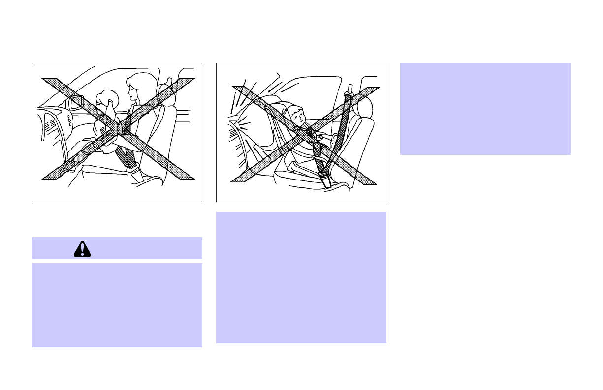
O Infants and small children should never
be carried on your lap. It is not possible
for even the strongest adult to resist the
forces of a severe accident. The child
could be crushed between the adult and
parts of the vehicle. Also, do not put the
same seat belt around both your child
and yourself.
O Never install a rear-facing child restraint
in the front seat. An inflating supplemental front air bag could seriously injure or kill your child. A rear-facing child
restraint must only be used in the rear
seat.
Safety — Seats, seat belts and supplemental restraint system 1-19
O INFINITI recommends that the child re-
straint be installed in the rear seat. According to accident statistics, children
are safer when properly restrained in the
rear seat than in the front seat.
O An improperly installed child restraint
could lead to serious injury or death in
an accident.
In general, child restraints are designed to
be installed with the lap portion of a
lap/shoulder seat belt. In addition, this vehicle is equipped with a universal child restraint lower anchor system, referred to as
the LATCH (Lower Anchors and Tethers for
CHildren) system. Some child restraints include two rigid or webbing-mounted attachments that can be connected to these
lower anchors. For details, see “LATCH
(Lower Anchors and Tethers for CHildren)
SYSTEM” later in this section.
Child restraints for infants and children of
various sizes are offered by several manufacturers. When selecting any child restraint, keep the following points in mind:
O choose only a restraint with a label cer-
tifying that it complies with Federal Motor Vehicle Safety Standard 213 or
Page 30

Canadian Motor Vehicle Safety Standard 213.
O check the child restraint in your vehicle
to be sureit is compatiblewith the vehicle’s seat and seat belt system.
O if the child restraint is compatible with
your vehicle, place your child in the
child restraint and check the various
adjustments to be sure the child restraint is compatible with your child.
Choose a child restraint that is designed for your child’s height and
weight. Always follow all recommended
procedures.
All U.S. states and Canadian provinces require that infants and small children be restrained in approved child restraints at all
times while the vehicle is being operated.
WARNING
O Improper use of a child restraint can in-
crease the risk or severity of injury for
both the childand other occupants of the
vehicle.
O Follow all of the child restraint manufac-
turer’s instructions for installation and
use. When purchasing a child restraint,
be sure to select one which will fit your
child and vehicle. It may not be possible
to properly install some types of child restraints in your vehicle.
O If the child restraint is not anchored
properly, the risk of a child being injured
in a collision or a sudden stop greatly increases.
O Adjustable seatbacks should be posi-
tioned to fit thechild restraint,but as upright as possible.
O After attaching the child restraint, test it
before you place the child in it. Push it
from side to side. Try to tug it forward
and check to see if the belt holds the restraint in place. The child restraint
should not move more than 1 inch (25
mm). If the restraint is not secure,
tighten the belt as necessary, or put the
restraint in another seat and test it
again. You may need to try a different
child restraint. Not all child restraints fit
in all types of vehicles.
O If you must install a front facing child re-
straint in the front seat, see “Child restraint installation on front passenger
seat” later in this section for details.
O When your child restraint is not in use,
keep it secured with a seat belt to prevent it from being thrown around in case
of a sudden stop or accident.
CAUTION
Remember that a child restraint left in a
closed vehicle can become very hot. Check
the seating surface and buckles before
placing your child in the child restraint.
1-20 Safety — Seats, seat belts and supplemental restraint system
Page 31

CHILD RESTRAINT INSTALLATION
ON REAR SEAT OUTBOARD OR
CENTER POSITIONS
WARNING
O The three-point seat belt in your vehicle
is equipped with an automatic locking
mode retractor which must be usedwhen
installing a child restraint.
O Failure to use the automatic locking
mode will result in the child restraint not
being properly secured. The restraint
could tip over or otherwise be unsecured
and cause injury to the child in a sudden
stop or collision.
O When installing a child restraint system
in the rear center position both the
center seat belt connector tongue and
buckle tongue must be secured. See “Attaching rear center seat belt” earlier in
this section.
Rear outboard seat
SSS0252A
Front facing
When you install a child restraint in a rear
outboard or center seat, follow these
steps:
1. Position the child restraint on the seat.
Always follow the child restraint manufacturer’s instructions. The back of the
child restraint should be secured
against the vehicle seatback. If necessary, adjust or remove the head restraint to obtain the correct child restraint fit. See “Head restraint adjustment” earlier inthis section. Ifthe head
restraint is removed, store it in a
Safety — Seats, seat belts and supplemental restraint system 1-21
Rear center seat
SSS0342
secure place. Besure to installthe head
restraint when the child restraint is removed. If the seating position does not
have an adjustable headrestraint and it
is interfering with the proper child restraint fit, try another seating position
or a different child restraint.
Page 32

SSS0253E SSS0254E SSS0332A
2. Route the seat belt tongue through the
child restraint and insert it into the
buckle until you hear and feel the latch
engage.
Be sure to follow the child restraint
manufacturer’s instructions for belt
routing.
3. Pull on the shoulder belt until all of the
belt is fully extended. At this time, the
belt retractor isin the automaticlocking
mode (child restraint mode). It reverts
back to emergency locking mode when
the belt is fully retracted.
1-22 Safety — Seats, seat belts and supplemental restraint system
4. Allow the seat belt to retract. Pull up on
the shoulder belt toremove any slackin
the belt.
Page 33

SSS0333 SSS0357
5. Before placing the child in the child restraint, use force to push the child restraint from side to side, and push it
forward to make sure that it is securely
held in place. It should not move more
than 1 inch (25 mm). If it does move
more than 1 inch(25 mm), pullagain on
the shoulder belt to further tighten the
child restraint. If unable to properly secure the restraint, move the restraint to
another rear seating position and try
again, or try a different child restraint.
Not all child restraints fit in all types of
vehicles.
6. Check that the retractor is in the automatic locking mode by trying to pull
more belt out of the retractor. If you
cannot pull any more belt webbing out
of the retractor, the belt is in the automatic locking mode.
7. Check to make sure that the child restraint is properly secured prior to each
use. If the belt is not locked, repeat
steps 3 through 6.
After the child restraint is removed and the
seat belt is fully retracted, the automatic
locking mode (child restraint mode) will be
canceled.
Rear outboard seat
Rear facing
When you install a child restraint in a rear
outboard or center seat, follow these
steps:
1. Position the child restraint on the seat.
Always follow the restraint manufacturer’s instructions.
Safety — Seats, seat belts and supplemental restraint system 1-23
Page 34

Rear center seat
SSS0358
2. Route the seat belt tongue through the
child restraint and insert it into the
buckle until you hear and feel the latch
engage.
Be sure to follow the child restraint
manufacturer’s instructions for belt
routing.
1-24 Safety — Seats, seat belts and supplemental restraint system
SSS0335 SSS0258A
3. Pull on the shoulder belt until all of the
belt is fully extended. At this time, the
belt retractor isin the automaticlocking
mode (child restraint mode). It reverts
back to emergency locking mode when
the belt is fully retracted.
Page 35

SSS0259A SSS0260A
6. Check that the retractor is in the automatic locking mode by trying to pull
more belt out of the retractor. If you
cannot pull any more belt webbing out
of the retractor, the belt is in the automatic locking mode.
7. Check to make sure that the child restraint is properly secured prior to each
use. If the belt is not locked, repeat
steps 3 through 6.
After the child restraint is removed and the
seat belt is allowed to wind back into the
retractor, the automatic locking mode
(child restraint mode) is canceled.
4. Allow the seat belt to retract.Pull up the
shoulder belt to removeany slack inthe
belt.
5. Before placing the child in the child restraint, use force to push the child restraint from side to side, and tug it forward to make sure that it is securely
held in place. It should not move more
than 1 inch (25 mm). If it does move
more than 1 inch(25 mm), pullagain on
the shoulder belt to further tighten the
child restraint. If unable to properly secure the restraint, move the restraint to
another rear seating position and try
again, or try a different child restraint.
Not all child restraints fit in all types of
vehicles.
Safety — Seats, seat belts and supplemental restraint system 1-25
Page 36

back. A label is attached to the seatback to
help you locate the LATCH system anchors.
O Attach LATCH system compatible child
restraints only at the locations shown. If
a child restraint is not secured properly,
your child could be seriously injured or
killed in an accident.
O Do not secure a child restraint in the rear
center seating position using the LATCH
SSS0613
LATCH (LOWER ANCHORS AND
TETHERS FOR CHILDREN) SYSTEM
1
LATCH lower anchor points (right)
j
2
LATCH lower anchor points (left)
j
3
LATCH label
j
The LATCH (Lower Anchors and Tethers for
CHildren) anchor points are located in the
seat cushions of the rear outboard seating
positions only. Do not attempt to install a
child restraint in the center position using
the LATCH anchors.
The LATCH system anchors are located at
the rear of the seat cushion near the seat-
system anchors. The child restraint will
not be secured properly.
O The LATCH system anchors are designed
to withstand only those loads imposed
by correctly fitted child restraints. Under
no circumstance are they to be used for
adult seat belts or harnesses.
Some child restraints include two rigid or
webbing-mounted attachments that can be
connected to two anchors located at certain seating positions in your vehicle. This
system is known as the LATCH system. This
system may also be referred to as the
ISOFIX or ISOFIX compatible system. With
1-26 Safety — Seats, seat belts and supplemental restraint system
WARNING
this system, you do not have to use a vehicle seat belt to secure the child restraint.
Your vehicle is equipped with special anchor points that are used with LATCH
system compatible child restraints. Check
your child restraint fora label statingthat it
is compatible with the LATCH system. This
information may also be in the instructions
provided by the child restraint manufacturer. If you have such a child restraint, refer to the illustration for the rear seating
positions equipped with LATCH system anchors which canbe used tosecure the child
restraint.
Some child restraints may also require the
use of a top tether strap. See “Top tether
strap child restraint” later in this section
for installation instructions.
When installing a child restraint, carefully
read and follow the instructions in this
manual and those supplied with the child
restraint.
When you install a LATCH system compatible child restraint to the lower anchor attachments in the rear seat, follow these
steps.
Page 37

WARNING
Inspect the lower anchors by inserting your
fingers into the lower anchor area and
feeling to make sure there are no obstructions over the LATCH system anchors, such
as seat belt webbing or seat cushion material. The child restraint will not be secured
properly if the LATCH system anchors are obstructed.
side and tug it forward to make sure
that the child restraint is securely held
in place. It should not move more than
1 inch (25 mm).
3. Check to make sure that the child restraint is properly secured prior to each
use.
1. To install the LATCH system compatible
child restraint, insert the child restraint
LATCH system anchor attachments into
the anchor points on the seat.
To assist in attaching the child restraint
to the lower anchors, recline the seatback, latch the anchor attachments to
the anchors, and then return the seatback to its normal, locked position. If
the child restraint is equipped with a
top tether, see “Top tether strap child
restraint” later in this section for installation instructions.
2. After attaching the child restraint and
before placing the child in it, use force
to push the child restraint from side to
SSS0359
TOP TETHER STRAP CHILD
RESTRAINT
WARNING
O Child restraint anchor points are de-
signed to withstand only those loads imposed by correctly fitted child restraints.
Under no circumstances are they to be
used for adult seat belts or harnesses.
Safety — Seats, seat belts and supplemental restraint system 1-27
Page 38

O After removing a rear seat head restraint
for top tether installation, store it securely to preventit from causing injury to
passengers or damage to the vehicle in
case of sudden braking or an accident.
Always replace it and adjust properly
when top tether is no longer in use.
If your child restraint has a top tether
strap, it must be secured to the anchor
point provided behind its position.
First, adjust the seatback so that it is upright. Then secure the child restraint with
the rear seat belt or the LATCH system (outboard positions), as applicable. Remove
the anchor cover from the anchor point as
illustrated. Keep the removed cover ina secure place to prevent loss or damage.
Remove the head restraint from the seatback. Store it in a secure place. Position
the top tetherstrap over thetop ofthe seatback and secure it to the tether anchor
bracket that providesthe straightest installation. Tighten thetether strap accordingto
the manufacturer’s instruction to remove
any slack.
For best child restraint fit, see the child restraint installation instructions in this section and the child restraint manufacturer’s
instructions.
Anchor point locations
Anchor points are located on the ceiling
above the luggage room.
If you have any questions when installing
a top strap child restraint on the rear seat,
consult an INFINITI dealer for details.
1-28 Safety — Seats, seat belts and supplemental restraint system
Page 39

CHILD RESTRAINT INSTALLATION
ON FRONT PASSENGER SEAT
WARNING
O Never install a rear-facing child restraint
in the front passenger seat. Supplemental front air bags inflate with great
force. A rear-facing child restraint could
be struck by the supplemental front air
bag in a crash and could seriously injure
or kill your child.
SSS0300A
O INFINITI recommends that child re-
straints be installed in the rear seat.
However, if you must install a forwardfacing child restraint inthe front passenger seat, move the passenger seat to the
rearmost position. Also,be surethe front
passenger air bag status light is illuminated to indicate the passenger air bag
is OFF. See “Front passenger air bag and
status light” later in this section for details.
O A child restraint with a top tether strap
should not be used in the front passenger seat.
O The passenger three-point seat belt is
equipped with an automatic locking
mode retractor which must be used
when installing a child restraint.
O Failure to use the automatic locking
mode will result in the child restraint not
being properly secured. The restraint
could tip over or otherwise be unsecured
and cause injury to the child in a sudden
stop or collision. Also, it can change the
operation of the front passenger air bag.
See “Front passenger air bag and status
light” later in this section.
Safety — Seats, seat belts and supplemental restraint system 1-29
Page 40

The back of the child restraint should be
secured against the vehicle seatback. If
necessary, adjust or remove the head restraint to obtain the correct child restraint
fit. See “Head restraint adjustment” earlier
in this section. If the head restraint is removed, store it ina secure place. Be sure to
install the head restraint when the child restraint is removed. If the seating position
does not have an adjustable head restraint
and it isinterfering with theproper child restraint fit, try another seating position or a
different child restraint.
SSS0301B SSS0360
Front facing
If you must install a child restraint in the
front seat, follow these steps:
1. Position the child restraint on the front
passenger seat. It should be placed in
a front facing direction only. Move the
seat to the rearmost position. Adjust
the head restraint to its highest position. Always follow the child restraint
manufacturer’s instructions. Child re-
straints for infants must be used in the
rear facing direction and therefore
must not be used in the front seat.
1-30 Safety — Seats, seat belts and supplemental restraint system
2. Route the seat belt tongue through the
child restraint and insert it into the
buckle until you hear and feel the latch
engage. Be sure to follow the child restraint manufacturer’s instructions for
belt routing.
Page 41

SSS0361 SSS0331A SSS0302C
3. Pull on the shoulder belt until all of the
belt is fully extended. At this time, the
belt retractor isin the automaticlocking
mode (child restraint mode). It reverts
back to emergency locking mode when
the belt is fully retracted.
4. Allow the seat belt to retract. Pull up on
the shoulder belt toremove any slackin
the belt.
Safety — Seats, seat belts and supplemental restraint system 1-31
5. Before placing the child in the child restraint, use force to push the child restraint from side to side, and tug it forward to make sure that it is securely
held in place. It should not move more
than 1 inch (25 mm). Before placing the
child in the child restraint, use force to
tilt the child restraint from side to side,
and tug it forwardto make sure that it is
securely held in place. It should not
move more than 1 inch (25 mm). If it
does move more than 1 inch (25 mm),
pull again on the shoulder belt to further tighten the child restraint. If un-
Page 42

BOOSTER SEATS
able to properly secure the restraint,
move the restraint to another rear seating position and try again, or try a different child restraint. Not all child restraints fit in all types of vehicles.
6. Check that the retractor is in the automatic locking mode by trying to pull
more belt out of the retractor. If you
cannot pull any more belt webbing out
of the retractor, the belt is in the automatic locking mode.
7. Check to make sure that the child restraint is properly secured prior to each
use. If the lap belt is not locked, repeat
steps 3 through 6.
8. Turn the ignition switch to the ON position. The passenger air bag status light
should illuminate. Ifthis light is
not illuminated, see “Front passenger
air bag and status light” later in this
section. Move the child restraint to an-
other seating position. Have the
system checked by an INFINITI dealer.
After the child restraint is removed and the
seat belt is fully retracted, the automatic
locking mode (child restraint mode) will be
canceled.
PRECAUTIONS ON BOOSTER SEATS
WARNING
O Infants and smallchildren shouldalways
be placed in an appropriate child restraint or booster seat whileriding in the
vehicle. Failure to use a child restraint or
booster seat can result in serious injury
or death.
O Infants and small children should never
be carried on your lap. It is not possible
for even the strongest adult to resist the
forces of a severe accident. The child
could be crushed between the adult and
parts of the vehicle. Also, do not put the
same seat belt around both your child
and yourself.
O INFINITI recommends that the booster
seat be installed in the rear seat. According to accident statistics, children are
safer when properly restrained in the
rear seat than in the frontseat.
O A booster seat must only be installed in a
seating position that has a lap/shoulder
belt. Failure to use a three-point type
seat belt witha booster seatcan result in
a serious injury in sudden stop or collision.
O An improperly installed booster seat
could lead to serious injury or death in
an accident.
1-32 Safety — Seats, seat belts and supplemental restraint system
Page 43

LRS0455 LRS0453 LRS0464
WARNING
Do not use towels, books, pillows or other
items in place of a booster seat. Items such
as these may move during normal driving or
a collision and result in serious injury or
death. Booster seats are designedto be used
with a lap/shoulder belt. Booster seats are
designed to properly route the lap and
shoulder portions of the seat belt over the
strongest portions of a child’s body to pro-
vide the maximum protection during a
collision.
Booster seats of various sizes are offered
by several manufacturers. When selecting
any booster seat, keep the following points
in mind:
O Choose only a booster seat with a label
certifying that it complies with Federal
Motor Vehicle Safety Standard 213 or
Canadian Motor Vehicle Safety Standard 213.
Safety — Seats, seat belts and supplemental restraint system 1-33
O Check the booster seat in your vehicle
to be sureit is compatiblewith the vehicle’s seat and seat belt system.
O Make sure the child’s headwill be prop-
erly supported by the booster seat or
vehicle seat. Theseatback must beat or
above the center of the child’s ears. For
example, if a low back booster seat
is chosen, the vehicleseatback must be
at or above the center of the child’s
ears. If the seatback is lower than the
center of the child’s ears, a high back
booster seat
2
should be used.
j
j
1
Page 44

O If the booster seat is compatible with
your vehicle, place your child in the
booster seat and check the various adjustments to be sure the booster seat is
compatible with your child. Always
follow all recommended procedures.
All U.S. states and Canadian provinces or
territories require that infants and small
children be restrained in anapproved child
restraint at all times while the vehicle is
being operated.
WARNING
O Improper use of a booster seat can in-
crease the risk or severity of injury for
both the childand other occupants of the
vehicle.
O Follow all of the booster seat manufac-
turer’s instructions for installation and
use. When purchasing a booster seat, be
sure to selectone which willfit yourchild
and vehicle. It may not be possible to
properly install some types of booster
seats in your vehicle.
O If the booster seat and seat belt are not
used properly, the risk of a child being
injured in a collision or a sudden stop
greatly increases.
O Adjustable seatbacks should be posi-
tioned to fit the booster seat, but as upright as possible.
O After placingthe childin the boosterseat
and fastening the seat belt, make sure
the shoulder portion of the belt is away
from the child’s face and neck and the
lap portion of the belt does not cross the
abdomen.
O Do not put the shoulder belt behind the
child or under the child’s arm. If you
must install a booster seat in the front
seat, see “Booster seat installation on
front passenger seat” later in this section.
O When your booster seat is not in use,
keep it secured with a seat belt to prevent it from being thrown around in case
of a sudden stop or accident.
CAUTION
Remember thata booster seatleft ina closed
vehicle can become very hot. Checkthe seating surface and buckles before placing your
child in the booster seat.
1-34 Safety — Seats, seat belts and supplemental restraint system
Page 45

Outboard position
LRS0452
BOOSTER SEAT INSTALLATION ON
REAR SEAT OUTBOARD OR CENTER
POSITIONS
CAUTION
Do not use the lap/shoulder belt automatic
locking mode whenusing a booster seat with
the seat belts. When you install a booster
seat in the rear seat, follow these steps:
Center position
LRS0451
1. Position the booster seat on the seat.
Only place it in a front facing direction.
Always follow the booster seat manufacturer’s instructions.
2. The booster seat should be positioned
on the vehicle seatso that itis stable. If
necessary, adjust or remove the head
restraint to obtain the correct booster
seat fit. See “Head restraint adjustment” earlier inthis section. Ifthe head
restraint is removed, store it in a secure
place. Be sure to install the head restraint when the booster seat is removed. If the seating position does not
have an adjustable headrestraint and it
Safety — Seats, seat belts and supplemental restraint system 1-35
is interfering with the proper booster
seat fit, try another seating position or
a different booster seat.
3. Position the lap portion of the seat belt
low and snug on the child’s hips. Be
sure to follow the booster seat manufacturer’s instructions for adjusting the
belt routing.
4. Pull the shoulder belt portion of the
seat belt toward the retractor to takeup
extra slack. Be sure the shoulder belt is
positioned across the top, middle portion of the child’s shoulder. Be sure to
follow the booster seat manufacturer’s
instructions for adjusting the belt
routing.
5. Follow the warnings, cautions and instructions for properly fastening a seat
belt shown in the “Three-point seat belt
with retractor” earlier in this section.
Page 46

LRS0454
BOOSTER SEAT INSTALLATION ON
FRONT PASSENGER SEAT
WARNING
INFINITI recommends that child restraints
be installed in the rear seat. However, if you
must install a booster seat in the front passenger seat, move the passenger seat to the
rearmost position. Also, be sure the front
passenger air bag status light is illuminated
to indicate the passenger air bag is OFF. See
“Front passenger air bag and status light”
later in this section for details.
If you must install a booster seat in the
front seat, follow these steps:
1. Move the seat to the rearmost position.
2. Position the booster seat on the seat.
Only place it in a front facing direction.
Always follow the booster seat manufacturer’s instructions.
3. The booster seat should be positioned
on the vehicle seatso that itis stable. If
necessary, adjust or remove the head
restraint to obtain the correct booster
seat fit. See “Head restraint adjustment” earlier inthis section. Ifthe head
restraint is removed, store it in a secure
place. Be sure to install the head restraint when the booster seat is removed. If the seating position does not
have an adjustable headrestraint and it
is interfering with the proper booster
seat fit, try another seating position or
a different booster seat.
4. Position the lap portion of the seat belt
low and snug on the child’s hips. Be
sure to follow the booster seat manufacturer’s instructions for adjusting the
belt routing.
5. Pull the shoulder belt portion of the
seat belt toward the retractor to takeup
extra slack. Be sure the shoulder belt is
positioned across the top, middle portion of the child’s shoulder. Be sure to
follow the booster seat manufacturer’s
instructions for adjusting the belt
routing.
6. Follow the warnings, cautions and instructions for properly fastening a seat
belt shown in the “Three-point seat belt
with retractor” earlier in this section.
7. When the ignition switch is turned to
the ON position, the passenger air bag
status light
illuminated, depending on the size of
the child and the type of booster seat
being used. See “Front passenger air
bag and status light” later in this section.
may or may not be
1-36 Safety — Seats, seat belts and supplemental restraint system
Page 47

SUPPLEMENTAL RESTRAINT SYSTEM
PRECAUTIONS ON SUPPLEMENTAL
RESTRAINT SYSTEM
This Supplemental Restraint System (SRS)
section contains important information
concerning the driver and passenger front
impact supplemental air bags (INFINITI
advanced air bag system), front seat sideimpact supplemental air bags, curtain
side-impact and rollover air bags and front
seat pre-tensioner seat belts.
Supplemental front impact air bag system:
The INFINITI advanced air bag system can
help cushion the impact force to the head
and chest of the driver and front passenger
in certain frontal collisions.
Supplemental side-impact air bag system:
This system can help cushion the impact
force to the chest area of the driver and
front passenger in certain side impact collisions. The front seat side-impact supplemental air bags are designed to inflate on
the side where the vehicle is impacted.
Supplemental curtain side-impact and rollover air bag system:
cushion the impactforce to thehead of occupants in front and rear outboard seating positions in certain side impact or rollover collisions. In a side impact, the curtain air bags
are designed to inflate on the side wherethe
vehicle is impacted. In a rollover both cur-
This system can help
tain air bags are designed to inflate and remain inflated for a short period of time.
These supplemental restraint systems are
designed to supplement the crash protection provided by the driver and passenger
seat belts and are not a substitute for
them. Seat belts should always be correctly worn and the occupant seated a suitable distance away from the steering
wheel, instrument panel and door finishers. (See “Seat belts” earlier in this section for instructions and precautions on
seat belt usage.)
After turning the ignition switch to the ON
position, the supplemental air bag
warning light illuminates. The supplemental air bag warning light will turn off
after about 7 seconds if the systems are
operational.
Safety — Seats, seat belts and supplemental restraint system 1-37
Page 48

WARNING
O The supplemental front air bags ordi-
narily will not inflate in the event of a
side impact, rear impact, rollover, or
lower severity frontal collision. Always
wear your seat belts to help reduce the
risk or severity of injury in various kinds
of accidents.
O The front passenger air bag will not in-
flate if the passenger air bag status light
SSS0131B
is lit or if the front passenger seat is unoccupied. See “Front passenger air bag
and status light” later in this section.
O The seat belts and the supplemental
front air bags are most effective when
you are sitting well back and upright in
the seat. The front air bags inflate with
great force. Even with the INFINITI Advanced Air Bag System, if you are unrestrained, leaning forward, sitting sideways or out of position in any way, you
are at greater risk of injury or death in a
crash. You may also receive serious or fatal injuries from the supplemental front
air bag if you are up against it when it inflates. Always sit back against the seatback and as far away as practical from
the steering wheel or instrument panel.
Always use the seat belts.
O The driver and front passenger seat belt
buckles are equipped with sensors that
detect if the seat belts are fastened. The
advanced air bag system monitors the
severity of acollision andseat beltusage
then inflates the air bags. Failure to
properly wear seat belts can increase the
risk or severity of injury in an accident.
O The front passenger seat is equipped
with an occupant classification sensor
(pressure sensor) that turns the front
passenger air bagOFF under someconditions. This sensor is only used in this
seat. Failure to be properly seated and
wearing the seat belt can increase the
risk or severity of injury in an accident.
See “Front Passenger air bag and status
light” later in this section.
1-38 Safety — Seats, seat belts and supplemental restraint system
Page 49

O Keep hands on the outside of the
steering wheel. Placing them inside the
steering wheel rim could increase the
risk that they are injured when the
supplemental front air bag inflates.
SSS0132B
Safety — Seats, seat belts and supplemental restraint system 1-39
Page 50

SSS0006
SSS0008
SSS0099
SSS0007
1-40 Safety — Seats, seat belts and supplemental restraint system
SSS0009
SSS0100
Page 51

WARNING
O Never let children ride unrestrained or
extend their hands orface out ofthe window. Do not attempt tohold them in your
lap or arms. Some examples of dangerous riding positions are shown in the
previous illustrations.
O Children may be severely injured or
killed when the supplemental front air
bags, side air bags or curtain sideimpact and rollover air bags inflate if
they are not properly restrained. Preteens and children should be properly restrained in the rear seat, if possible.
O Even withthe INFINITIAdvanced AirBag
System, never install a rear-facing child
restraint in the front seat. An inflating
supplemental front air bag could seriously injure or kill your child. See “Child
restraints” earlier in this section for details.
SSS0059A
WARNING
Supplemental side air bag and curtain sideimpact and rollover air bag:
O The supplemental side air bag and cur-
tain side-impact and rollover air bag ordinarily will not inflate in the event of a
frontal impact, rear impact or lower severity side collision. Always wear your
seat belts to help reduce the risk or severity of injury in various kinds of
accidents.
SSS0188A
O The seat belts, the supplemental side air
bags and curtain side-impact and rollover air bagsare mosteffective whenyou
are sitting well back and upright in the
seat. The side air bag and curtain sideimpact air baginflate withgreat force. Do
not allow anyone to place their hand, leg
or face near the side air bag on the side
of the seatback of the front seat or near
the side roof rails. Do not allow anyone
sitting in the front seats or rear outboard
seats to extend their hand out of the
Safety — Seats, seat belts and supplemental restraint system 1-41
Page 52

SSS0140 SSS0159 SSS0162
window or lean against the door. Some
examples of dangerous riding positions
are shown in the illustrations.
O When sitting in therear seat, do nothold
onto the seatbackof the frontseat. Ifthe
side air bag inflates, you may be seriously injured. Be especially careful with
children, who should always be properly
restrained.
O Do not use seat covers on the front seat-
backs. They may interfere with supple
mental side air bag inflation.
1-42 Safety — Seats, seat belts and supplemental restraint system
Page 53

1. Crash zone sensor
2. Supplemental curtain side-impact and
rollover air bags
3. Occupant classification system control
unit
4. Occupant classification sensor (pressure sensor)
5. Supplemental side air bag modules
6. Supplemental front air bag modules
7. Diagnosis sensor unit
8. Seat belt pre-tensioner retractor
SSS0597
9. Satellite sensors
10.Supplemental curtain side-impact and
rollover air bag modules
INFINITI ADVANCED AIR BAG
SYSTEM (front seats)
This vehicle is equipped with the INFINITI
advanced air bag system for the driver and
front passenger seats. This system is designed to meet certification requirements
under U.S. regulations. It is also permitted
in Canada. However, all of the information,
cautions and warnings in this manual still
apply and must be followed.
Safety — Seats, seat belts and supplemental restraint system 1-43
The driver supplemental front air bag is located in the center of the steering wheel.
The front passenger supplemental front air
bag is mounted in the instrument panel
above the glove box. The supplemental
front air bags are designed to inflate in
higher severity frontal collisions, although
they may inflate if the forces in another
type of collision are similar to those of a
higher severity frontal impact. They may
not inflate in certain frontal collisions. Vehicle damage (or lack of it) is not always an
indication of proper supplemental air bag
system operation.
The INFINITI advanced air bag system has
dual stage inflators. It also monitors information from the crash zone sensor, the diagnosis sensor unit, seat belt buckle
switches, occupant classification sensor
(pressure sensor) and passenger seat belt
tension sensor. Inflator operation is based
on the severity of a collision and seat belt
usage of the driver. For the front passenger, it additionally monitors the weight
of an occupant or object on the seat and
seat belt tension. Based on information
from the sensors, only one front air bag
may inflate in a crash, depending on the
crash severity and whether the front occupants are belted or unbelted. Additionally,
Page 54

the front passenger air bag may be automatically turned OFF under some conditions, depending on the weight detected
on the passenger seat and how the seat
belt is used. If the front passenger air bag
is OFF, the passenger air bag status light
will be illuminated (if the seat is unoccupied, the light will not be illuminated, but
the air bag will be off.). See “Front passenger air bag andstatus light” laterin this
section for further details.One front air bag
inflating does not indicate improper performance of the system.
If you have any questions about your air
bag system, contact an INFINITI dealer. If
you are considering modifications of your
vehicle due to a disability, you may also
contact an INFINITI dealer. Contact information is contained in the front of this
Owner’s Manual.
When a supplemental front airbag inflates,
a fairly loud noise may be heard, followed
by release of smoke. This smoke is not
harmful and does not indicate a fire. Care
should be taken to not inhale it, as it may
cause irritation and choking. Those with a
history of a breathing condition should get
fresh air promptly.
Supplemental front airbags, along withthe
use of seat belts, help to cushion the impact force on the faceand chest of thefront
occupants. They can help save lives and reduce serious injuries. However,an inflating
front air bag may cause facial abrasions or
other injuries. Front air bagsdo not provide
restraint to the lower body.
Even with INFINITI advancedair bags, seat
belts should be correctly worn and the
driver and passenger seated upright as far
as practical away from the steering wheel
or instrument panel. The supplemental
front air bags inflate quickly in order to
help protect the front occupants. Because
of this, the force of the front air bag inflating can increase the risk of injury if the
occupant is too close to, or is against the
front air bag module during inflation.
The front air bags deflate quickly after a
collision.
The supplemental front air bags operate
only when the ignition switch is in the ON
or START position.
After turning the ignition switch to the ON
position, the supplemental air bag
warning light illuminates. The supplemental air bag warning light will turn off
after about 7 seconds if the system is operational.
1-44 Safety — Seats, seat belts and supplemental restraint system
Page 55

SSS0614
Front passenger air bag and status
light
WARNING
The front passenger air bag is designed to
automatically turn OFF under some conditions. Read this section carefully to learn
how it operates. Proper use of the seat, seat
belt and child restraints is necessary for
most effective protection. Failure to follow
all instructions in thismanualconcerning the
use of seats, seat belts and child restraints
can increase the risk or severity of injury in
an accident.
Status light:
The front passenger air bag status light
The light operates as follows:
O Unoccupied passenger seat: The
O Passenger seat occupied by a small
O Occupied passenger seat and the pas-
is located on the map light cover.
air bag is OFF and will not inflate in a
crash.
adult, child or child restraint as outlined in this section: The
nates to indicate that the front passenger air bag is OFF and will not inflate
in a crash.
senger meets the conditions outlinedin
this section: The light
indicate that the front passenger air
bag is operational.
is OFF and the front passenger
illumi-
is OFF to
Safety — Seats, seat belts and supplemental restraint system 1-45
Front passenger air bag:
The front passenger air bag is designed to
automatically turn OFF when the vehicle is
operated under some conditions as described below in accordance with U.S.
regulations. If the front passenger air bag
is OFF, it will not inflate in a crash. The
driver air bag and other air bags in your vehicle are not part of this system.
The purpose of the regulation is to help reduce the risk of injury or death from an inflating air bag to certain front passenger
seat occupants, such as children, by requiring the air bag to be automatically
turned OFF. Certain sensors are used to
meet the requirements.
One sensor used is the occupant classification sensor (pressure sensor). It is in the
bottom of the front passenger seat cushion
and is designed to detect an occupant and
objects on the seat by weight. It works together with seat belt sensors described
later. For example, if a child is in the front
passenger seat, the advanced air bag
system is designed to turn the passenger
air bag OFF in accordance with the regulations. Also, if a child restraint of the type
specified in the regulations is on the seat,
its weight and the child’s weightcan be de-
Page 56

tected and cause the air bag to turn OFF.
The occupant classification sensor operation can vary depending on the front passenger seat belt sensors.
The front passenger seat belt sensors are
designed to detect if the seat belt is
buckled and the amount of tension on the
seat belt, such as when it is in the automatic locking mode (child restraint mode).
Based on the weight on the seat detected
by the occupant classification sensor and
the belt tension detected on the seat belt,
the advanced air bag system determines
whether the front passenger airbag should
be automatically turned OFF as required by
the regulations.
Front passenger seat adult occupants who
are properly seated and using the seat belt
as outlined in this manual should not
cause the passenger air bag to be automatically turned OFF. For small adults it
may be turned OFF. However, if the occupant takes his/her weight off the seat
cushion (for example, by not sitting upright, by sitting on an edge of the seat, or
by otherwise being out of position), this
could cause the sensor to turn the air bag
OFF. In addition,if the occupantimproperly
uses the seat belt in the automatic locking
mode (child restraint mode), this could
cause the air bag to be turned OFF. Always
be sure to be seated and wearing the seat
belt properly for the most effective protection by the seat belt and supplemental air
bag.
INFINITI recommends that pre-teens and
children be properly restrained in a rear
seat. INFINITI also recommends that appropriate child restraintsand booster seats
be properly installedin a rearseat. If this is
not possible, the occupant classification
sensor and seat belt sensors are designed
to operate as described above to turn the
front passenger air bag OFF for specified
child restraints as required by the regulations. Failing to properly secure child restrains and to use the automatic locking
mode (child restraint mode) may allow the
restraint to tip or move in an accident or
sudden stop. This can also result in the
passenger air bag inflating in a crash instead of being OFF. See “Child restraints”
earlier in this section for proper use and installation.
If the front passenger seat is not occupied,
the passenger air bag isdesigned not to inflate in a crash. However, heavy objects
placed on the seat could result in air bag
inflation, because of the object’s weight
detected by the occupant classification
1-46 Safety — Seats, seat belts and supplemental restraint system
sensor. Other conditions could also result
in air bag inflation, such as if a child is
standing on the seat, or if two children are
on the seat, contrary to the instructions in
this manual. Always be sure that you and
all vehicle occupants are seated and restrained properly.
Using the passenger air bag status light,
you can monitor when the front passenger
air bag is automatically turnedOFF with the
seat occupied. The light will not illuminate
when the front passenger seat is unoccupied.
If an adult occupant is in the seat but the
passenger air bag status light is illuminated (indicating that the air bag is OFF), it
could be that the personis a small adult, or
is not sitting on the seat properly or is not
using the seat belt properly.
If a child restraintmust be used in the front
seat, the passenger air bag status light
may or may not be illuminated, depending
on the size ofthe child andthe type ofchild
restraint being used. If the passenger air
bag status light is not illuminated (indicating that the air bag might inflate in a
crash), it could be that the child restraint or
seat belt is not being used properly. In rare
cases, the passenger air bag status light
Page 57

will not illuminate even though the air bag
is OFF.
If such situations happen, properly position and restrain the occupant or child restraint. Otherwise reposition the occupant
or child restraint in a rear seat. If you have
any questions about whether your passenger air bagis working asdesigned, your
INFINITI dealer can confirm that it is working properly by using a special tool.
The air bag system and passenger air bag
status light will take a few seconds to register a changein the passengerseat status.
For example, if a large adult who is sitting
in the front passenger seat exits the vehicle, the passenger air bag status light
will change from OFF to ON for a few seconds and then to OFF. This is normal
system operation and does not indicate a
malfunction.
If a malfunction occurs in the front passenger air bag system, the supplemental air
bag warning light
meter and gauges area, will blink. Have the
system checked by an INFINITI dealer.
, located in the
Other supplemental front air bag
precautions
WARNING
O Do not place any objects on the steering
wheel pad or on the instrument panel.
Also, do not place any objects between
any occupant and the steering wheel or
instrument panel. Such objects may become dangerous projectiles and cause
injury if the supplemental front air bag
inflates.
O Immediately after inflation, several front
air bag system components will be hot.
Do not touch them; you may severely
burn yourself.
O No unauthorized changes should be
made to any components or wiring of the
supplemental air bag system. This is to
prevent accidental inflation of the
supplemental air bag or damage to the
supplemental air bag system.
O Do not make unauthorized changes to
your vehicle’s electrical system, suspen-
sion system or front end structure. This
could affect proper operation of the
supplemental air bag system.
O Tampering with the supplemental front
air bag system may result in serious personal injury. Tampering includes
changes to the steering wheel and the
instrument panel assembly by placing
material over the steering wheelpad and
above the instrument panel or by installing additional trim material around the
air bag system.
O Modifying or tampering with the front
passenger seat may result in seriouspersonal injury. For example, do not change
the front seatsby placing material on the
seat cushion or by installing additional
trim material, such as seat covers, on the
seat. Additionally, do not stow any objects under the front passenger seat or
the seat cushion and seatback. Such objects may interfere with the proper operation of the occupant classification
sensor (pressure sensor).
Safety — Seats, seat belts and supplemental restraint system 1-47
Page 58

O No unauthorized changes should be
made to any components or wiring of the
seat belt system. This may affect the
supplemental front air bag system. Tampering with the seat belt system may result in serious personal injury.
O Work on and around the supplemental
front air bag system should be done by
an INFINITI dealer. Installation of electrical equipment should also be done by
an INFINITI dealer. The Supplemental
RestraintSystem (SRS)wiring shouldnot
be modified or disconnected. Unauthorized electrical test equipment and probing devices should not be usedon the air
bag system.
O A cracked windshield should be replaced
immediately by a qualified repair facility.
A cracked windshield could affect the
function of the supplementalair bag system.
O The SRS wiring harness connectors are
yellow and orange for easy identification.
When selling your vehicle, we request that
you inform the buyer about the supplemental front airbag system andguide the buyer
to the appropriate sections in this Owner’s
Manual.
1-48 Safety — Seats, seat belts and supplemental restraint system
SSS0190
Supplemental side air bag and
curtain side-impact and rollover air
bag system
The supplemental side air bags are located
in the outside of the seatback of the front
seats. The supplemental curtain sideimpact and rollover air bags are located in
the side roof rails. These systems are designed to meet voluntaryguidelines to help
reduce the risk of injury to out-of-position
occupants. However, all ofthe information,
cautions and warnings in this manual still
apply and must be followed. The supple-
mental side air bags and curtain side-
Page 59

impact and rollover air bags are designed
to inflate in higher severity side collisions,
although they may inflate if the forces in
another type of collision are similar to
those of a higherseverity side impact. They
are designed to inflate on the side where
the vehicle is impacted. They may not inflate in certain side collisions.
Curtain side-impact and rollover air bags
are also designed to inflate in certain types
of rollover collisions or near rollovers. Vehicle damage (or lack of it) is not always an
indication of proper supplemental side air
bag and curtain side-impact and rollover
air bag operation.
When the supplemental side air bag and
curtain side-impact air bag inflate, a fairly
loud noise may be heard, followed by release of smoke. This smoke is not harmful
and does not indicatea fire. Care shouldbe
taken not to inhale it, asit may cause irritation and choking. Those with a history of a
breathing condition should get fresh air
promptly.
Supplemental side air bags, along with the
use of seat belts, help to cushion the impact force on the chest of the front occupants. Curtain side-impact and rollover air
bags help to cushion the impact force to
the head of occupants in the front and rear
outboard seating positions. They can help
save lives and reduce serious injuries.
However, an inflating side air bag and curtain side-impact air bag may cause abrasions or other injuries. Supplemental side
air bags and curtain side-impact and rollover air bags do notprovide restraint to the
lower body.
The seat belts should be correctly worn and
the driver and passenger seated upright as
far as practical away from the side air bag.
Rear seat passengers should be seated as
far away as practical from the doorfinishers
and side roof rails. The side air bags and
curtain side-impact airbag inflate quicklyin
order to help protect the front occupants
and rear-outboard occupants. Because of
this, the force of the side air bag and curtain air bag inflatingcan increase the riskof
injury if the occupant is too close to, or is
against, these air bag modules during inflation. The side air bag will deflate quickly after the collision is over.
The curtain side-impactand rollover airbag
will remain inflated for a short time.
Safety — Seats, seat belts and supplemental restraint system 1-49
The supplemental side air bags and curtain side-impact and rollover air bags operate only when the ignition switch is in
the ON or START position.
After turning the ignition switch to the ON
position, the supplemental air bag
warning light illuminates. The supplemental air bag warning light will turn off
after about 7 seconds if the systems are
operational.
WARNING
O Do not place any objects near the seat-
back ofthe front seats. Also, do notplace
any objects (an umbrella, bag, etc.) between the front door finisher and the
front seat. Such objects may become
dangerous projectiles and cause injury if
the side airbag or curtainside-impact air
bag inflates.
O Immediately after inflation, several side
air bag and curtain side-impact and rollover air bag system components will be
hot. Do not touch them; you may severely burn yourself.
Page 60

O No unauthorized changes should be-
made to anycomponentsor wiring ofthis
side air bag and curtain side-impact air
bag system. This is to prevent accidental
inflation of the side air bag and curtain
side-impact air bag or damage to the
side air bag and curtain side-impact air
bag system.
O Do not make unauthorized changes to
your vehicle’s electrical system, suspension system or side panel. This could affect proper operation of the supplemental side air bag and curtain sideimpact air bag system.
O Tampering with the supplemental
system may result in serious personalinjury. For example, do not change the
front seat by placing material near the
seatback or by installing additional trim
material, such as seat covers, around the
side air bag.
O Work around and on the side air bag and
curtain side-impact air bag system
should be done by an INFINITI dealer.
Installation of electrical equipment
should also be done by an INFINITI
dealer. TheSRS wiring harnesses*should
not be modified or disconnected. Unauthorized electrical test equipment and
probing devices should not be used on
the side air bag system.
* The SRS wiring harnessesconnectors are
yellow for easy identification.
When selling your vehicle, we request that
you inform the buyer about the side air bag
and curtain side-impact air bag system and
guide the buyer to theappropriate sections
in this Owner’s Manual.
Pre-tensioner seat belt system (For
front seats)
WARNING
O The pre-tensioner seat belt cannot be re-
used after activation. It mustbe replaced
together with the retractor and buckle as
a unit.
O If the vehicle becomes involved in a fron-
tal collision but the pre-tensioner is not
activated, be sure to have the pretensioner system checked and, if necessary,
replaced by an INFINITI dealer.
O No unauthorized changes should be
made to any components or wiring of the
pre-tensioner seat belt system.This is to
prevent accidental activation of the pretensioner seat belt or damage to the pretensioner seat belt operation. Tampering
with the pre-tensioner seat belt system
may result in serious personalinjury.
O Work around and on the pre-tensioner
system should be done by an INFINITI
dealer. Installation of electrical equipment should also be done by an
INFINITI dealer. Unauthorized electrical
test equipment and probing devices
should not be used on the pre-tensioner
seat belt system.
O If you need to dispose of the pre-
tensioner or scrap the vehicle, contact an
INFINITI dealer. Correct pre-tensioner
disposal procedures are set forth in the
appropriate INFINITI Service Manual.
Incorrect disposal procedures could
causepersonal injury.
1-50 Safety — Seats, seat belts and supplemental restraint system
Page 61

The front seat pre-tensioner seat belt
system activates in conjunction with the
front supplemental air bag systems.
Working with the seat belt retractor, it
helps tighten the seat belt when the vehicle becomes involved in certain types of
collisions, helping to restrain front seat occupants.
The pre-tensioner is encased with the seat
belt’s retractor. These seat belts are used
in the same wayas conventional seatbelts.
When the pre-tensioner seat belt activates,
smoke is released and a loud noise may be
heard. The smoke is not harmful and does
not indicate a fire. Care should be taken
not to inhale it as it may cause irritation
and choking. Those with a history of a
breathing condition should get fresh air
promptly.
If any abnormality occurs in the pretensioner system, the supplemental air
bag warning light
will flash intermittently or will turn on for 7
seconds and remain on after the ignition
switch has been turned to the ON or START
position. In this case, the pre-tensioner
seat belt may not function properly. They
must be checked and repaired. Take your
vehicle to an INFINITI dealer.
will not come on,
When selling your vehicle, we request that
you inform the buyer about the pretensioner seat belt system and guide the
buyer to the appropriate sections in this
Owner’s Manual.
Safety — Seats, seat belts and supplemental restraint system 1-51
SSS0362
1
j
SRS air bag
The warning labels are located on the surface of the sun visor.
2
j
SRS side-impact air bag
The warning label is located on the side of
the passenger’s side center pillar.
SUPPLEMENTAL AIR BAG WARNING
LABELS
Warning labels about the supplemental
front air bag and supplementalside-impact
air bag systems areplaced in the vehicle as
shown in the illustration.
Page 62

SPA1097
SUPPLEMENTAL AIR BAG WARNING
LIGHT
The supplemental air bag warning light,
displaying
monitors the circuits of the supplemental
front air bag, supplemental side air bag
and curtain side-impact and rollover air
bag systems, and pre-tensioner seat belt
systems. The circuits monitored by the air
bag warning light are the diagnosis sensor
unit, crash zone sensor, rollover sensors,
satellite sensors, front air bag modules,
side air bag modules, curtain side-impact
in the instrument panel,
air bag modules, pre-tensioner seat belts
and all related wiring.
After turning the ignition switch to the ON
or START position, the supplemental air
bag warning light illuminates. The supplemental air bag warning light will turn off after about 7 seconds if the system is operational.
If any ofthe following conditions occur, the
supplemental front air bag, supplemental
side air bag andcurtain side-impact air bag
systems, and pre-tensioner seat belt systems need servicing:
O The supplemental air bag warning light
remains on after approximately 7 seconds.
O The supplemental air bag warning light
flashes intermittently.
O The supplemental air bag warning light
does not come on at all.
Under these conditions, the supplemental
front air bags, supplemental side air bags,
curtain side-impact air bags and/or pretensioner seat belt may not operate properly. It must be checkedand repaired. Take
your vehicle to an INFINITI dealer.
WARNING
If the supplemental air bag warning light is
on, it couldmean thatthe supplementalfront
air bag, supplemental side air bag, curtain
air bag systems and/or pre-tensioner seat
belt system will not operate in an accident.
To help avoid injury to yourself or others,
have your vehicle checked by an INFINITI
dealer as soon as possible.
Repair and replacement procedure
The supplemental front air bags, supplemental side air bags, curtain side-impact
air bags and pre-tensioner seat belt are designed to inflate on a one-time-only basis.
As a reminder, unless it is damaged, the
supplemental air bag warning light will remain illuminated after inflation has occurred. Repair and replacement of these
systems should be done only by an INFINITI dealer.
When maintenance work is required on the
vehicle, the supplemental front air bags,
side air bags, curtain air bags, related
parts and pre-tensioner seat beltshould be
1-52 Safety — Seats, seat belts and supplemental restraint system
Page 63

pointed out to the person conducting the
maintenance. The ignition switch should
always be in the LOCK position when working under the hood or inside the vehicle.
WARNING
O Once a supplemental front air bag,
supplemental side air bag or curtain air
bag has inflated, the air bag module will
not function again and must be replaced.
Additionally, if any of the supplemental
front air bags inflate, the activated pretensioner seat belts must also be replaced. The air bag module and pretensioner seat belt system should be replaced by an INFINITI dealer. The air
bag modules and pre-tensioner seat belt
system cannot be repaired.
O The supplemental front air bag, side air
bag and curtain side-impact/rollover air
bag systems, and pre-tensioner seat belt
system should be inspected by an
INFINITI dealer ifthere isany damage to
the front end or side portion of the
vehicle.
If you need to dispose of these supple-
O
mental systems or scrap the vehicle, contact an INFINITI dealer. Correct disposal
procedures are set forth in the appropriate INFINITIService Manual. Incorrect
disposal procedures could cause personal
injury.
Safety — Seats, seat belts and supplemental restraint system 1-53
Page 64

2 Instruments and controls
Instrument panel.............................................. 2-2
Meters and gauges ........................................... 2-3
Speedometer and odometer......................... 2-4
Tachometer ................................................. 2-4
Engine coolant temperature gauge............... 2-5
Fuel gauge .................................................. 2-5
Compass display .............................................. 2-6
Warning/indicator lights and audible
reminders......................................................... 2-9
Checking bulbs............................................ 2-9
Warning lights........................................... 2-10
Indicator lights ......................................... 2-15
Audible reminders ..................................... 2-17
Security systems ............................................ 2-18
Vehicle security system ............................. 2-18
INFINITI Vehicle Immobilizer System ........ 2-20
Windshield wiper and washer switch .............. 2-21
Rear window wiper and washer switch ............ 2-22
Rear window and outside mirror defroster
switch ............................................................ 2-23
Headlight and turn signal switch ..................... 2-23
Xenon headlights ...................................... 2-23
Headlight switch ....................................... 2-24
Daytime running light system
(Canada only) ........................................... 2-27
Instrument brightness control ................... 2-27
Turn signal switch ..................................... 2-28
Fog light switch ......................................... 2-28
Hazard warning flasher switch......................... 2-28
Horn............................................................... 2-29
Heated seats (if so equipped) .......................... 2-29
Lane departure warning (LDW) switch
(if so equipped) .............................................. 2-30
SNOW mode switch......................................... 2-31
Vehicle dynamic control (VDC) off switch ......... 2-31
Clock.............................................................. 2-32
Adjusting the time ..................................... 2-32
Power outlet ................................................... 2-32
Storage .......................................................... 2-34
Sunglasses holder..................................... 2-34
Storage box............................................... 2-35
Cup holders............................................... 2-35
Glove box.................................................. 2-36
Console box .............................................. 2-38
Luggage floor boxes (if so equipped).......... 2-39
Card holder (for driver’s side)..................... 2-39
Cargo net (if so equipped).......................... 2-39
Page 65

Tonneau cover (if so equipped) .................. 2-40
Windows ........................................................ 2-41
Power windows ......................................... 2-41
Sunroof (if so equipped).................................. 2-43
Automatic sunroof ..................................... 2-43
Interior light................................................... 2-45
Room light................................................. 2-45
Map light .................................................. 2-45
Ceiling light (if so equipped) ...................... 2-46
Rear personal light ................................... 2-46
Luggage room light.................................... 2-47
Vanity mirror light........................................... 2-47
HomeLink
Universal Transceiver (if so
equipped)....................................................... 2-47
Programming HomeLink
Programming HomeLink
........................... 2-48
for Canadian
customers ................................................. 2-49
Operating the HomeLink
Universal
Transceiver................................................ 2-50
Programming trouble-diagnosis................. 2-50
Clearing the programmed information........ 2-50
Reprogramming a single HomeLink
button....................................................... 2-50
If your vehicle is stolen.............................. 2-51
Page 66

INSTRUMENT PANEL
2-2 Instruments and controls
SSI0182
1. Outside mirror remote control
2. Headlight, fog light and turn signal
switch
3. Trip odometer reset knob
4. Instrument brightness control switch
5. Headlight aiming control switch
6. Trip odometer select knob
7. Steering switch for Audio/Bluetooth
Hands-Free Phone System
(if so equipped)
8. Security indicator light
9. Meters and gauges
10. Driver supplemental air bag
11. Cruise control main/set switch or In-
telligent cruise control switch (if so
equipped)
12. Windshield wiper/washer switch
13. Ignition switch
14. Center ventilator
15. Display/Navigation system
(if so equipped)*
16. Audio system
17. Center multi-function control panel
18. Front passenger supplemental air bag
19. Lane departure warning (LDW) switch
(if so equipped)
20. Hood release handle
21. Fuse box
22. SNOW mode switch
23. Parking brake
Page 67

24. Vehicle dynamic control (VDC) OFF
switch
25. Tilting/telescopic steering wheel
switch
26. Storage box and power outlet
27. Hazard warning flasher switch
28. Automatic transmission selector lever
29. Heated seat switch
30. Clock
31. Automatic climate control system
32. Glove box
*: Refer to the separate Navigation System
Owner’s Manual. (if so equipped)
METERS AND GAUGES
SIC2135
1. Warning/Indicator lights
2. Tachometer
3. Speedometer
4. Engine coolant temperature gauge
5. Intelligent cruise control system dis-
play (if so equipped)
6. Automatic transmission position indicator
7. Odometer (Total/Twin trip)
8. Fuel gauge
Instruments and controls 2-3
Page 68

SIC2136
SPEEDOMETER AND ODOMETER
Speedometer
The speedometer indicates vehicle speed
(MPH and km/h).
Odometer/Twin trip odometer
The odometer/twin trip odometer are displayed when the ignition switch is in the
ON position.
The odometer
the vehicle has been driven.
The twin trip odometer
tance of individual trips.
Changing the display:
Pushing the trip knob
play as follows:
TRIP A → TRIP B → TRIP A
Resetting the trip odometer:
Push and hold the reset knob
the trip odometer to zero.
Elapsed time, driving distance and average
speed information are also available. Refer
to “How to use “TRIP” button” in the “4.
Display screen, heater, air conditioner and
audio systems” section.
1
records the total distance
j
2
records the dis-
j
3
changes the dis-
j
4
j
to reset
SIC2551
TACHOMETER
The tachometer indicates engine speed in
revolutions per minute (rpm).
Do not rev the engine into the red zone
j
A
CAUTION
When engine speed approaches the red
zone, shift to a higher gear. Operating the
engine in the red zone may cause serious engine damage.
.
2-4 Instruments and controls
Page 69

CAUTION
If the gauge indicates engine coolant temperature near the hot (H) end of the normal
range, reducevehicle speed to decrease temperature. If the gauge is over the normal
A
range
j
, stop the vehicle as soon as safely
possible. If theengine is overheated, continued operation of the vehicle may seriously
damage the engine. See “If your vehicle
overheats” in the “6. In case of emergency”
SIC2137A SIC3119
section for immediate action required.
ENGINE COOLANT TEMPERATURE
GAUGE
The gauge indicates the engine coolant
temperature.
The engine coolant temperature is normal
when the gauge indicates within the range
A
j
.
The engine coolant temperature will vary
with the outside air temperature and
driving conditions.
FUEL GAUGE
The gauge indicates the approximate fuel
level in the tank.
The gauge may move slightly during
braking, turning, acceleration, or going up
or down hill.
The gauge needle is designed to move to
the E (Empty) position when the ignition
switch is turned to the OFF position.
Refill the fuel tank before the gauge registers Empty.
Instruments and controls 2-5
Page 70

COMPASS DISPLAY
The low fuel warning light
A
j
comes on
when the fuel tankis getting low. Refuelas
soon as it is convenient, preferably before
the gauge reaches E. There will be a small
reserve of fuel in the tank when the fuel
gauge needle reaches E.
The
indicates that the fuel-filler door
is located on the passenger’s side of the
vehicle.
CAUTION
O If the vehicle runs out of fuel, the
malfunction indicator lamp (MIL)
may comeon. Refuelas soonas possible.
After a few driving trips, the
should turn off. If the lamp remains on
after a few driving trips, have the vehicle
inspected by an INFINITI dealer.
O For additionalinformation, see“Malfunc-
tion indicator lamp (MIL)” later in this
section.
2-6 Instruments and controls
lamp
Type A
Type B
SIC3150
SIC3014
When the compass switch
the compass display
j
A
j
B
will indicate the di-
is pushed,
rection the vehicle is heading.
N: north
E: east
S: south
W: west
If the display reads “C” or compass switch
A
j
is pushed for 9 seconds (Type B), calibrate the compass by driving the vehicle in
3 complete circles at less than 5 MPH (8
km/h).
You can also calibrate the compass by driving your vehicle on your everyday route.
The compass will be calibrated once it has
tracked 3 complete circles.
To turn off the compass, push
j
A
again.
Page 71

SIC0611B
Zone variation change procedure
The difference betweenmagnetic north and
geographical north is known as variance.
In some areas, this difference can sometimes be great enough to cause false compass readings. Follow these instructions to
set the variance for your particular location
if this happens:
1. Push the compass switch for more than
3 seconds. The current zone number
will appear in the display.
2. Find your current location and variance
number on the zone map.
3. Push and hold the compass switch until
the new zone number appears in the
display, then release the switch. After
you release the switch, the display will
show a compass direction within a few
seconds.
Inaccurate compass direction:
1. With the display turned on, push the
compass switch for 3 seconds, until a
zone selection number is displayed in
the mirror compass window.
2. Push the compass switch repeatedly
(toggle) until the correct zone is displayed, then release the switch.
Instruments and controls 2-7
Page 72

3. The display returns to the normal compass mode within 10 seconds after the
switch is released.
4. If the vehicle changes zone, repeat
steps 1 thru 3. See map.
O If the compass deviates from the cor-
rect direction after repeated adjustment, have the compass checked at an
INFINITI dealer.
O The compass may not indicate the cor-
rect compass point in tunnels or while
driving up or down a steep hill.
(The compass returns to the correct
compass point when the vehicle moves
to an area where the geomagnetism is
stabilized.)
CAUTION
O Do not install a ski rack, antenna, etc.
which are attached to the vehicle by
means of a magnet. They affect the operation of the compass.
O When cleaning the mirror, use a paper
towel or similar material dampened with
glass cleaner. Do not spray glass
cleaner directly on the mirror as it may
cause the liquid cleaner to enter the mirror housing.
2-8 Instruments and controls
Page 73

WARNING/INDICATOR LIGHTS AND
AUDIBLE REMINDERS
All-Wheel Drive (AWD) warning light (AWD
models)
or Anti-lock brake warning light
Automatic transmission check warning
light
Preview Function warning light (Orange;
if so equipped)
or Brake warning light Low washer fluid warning light Malfunction indicator lamp (MIL)
Charge warning light Seat belt warning light Slip indicator light
Door open warning light Supplemental air bag warning light Snow mode indicator light
Engine oil pressure warning light
P position selecting warning light and
chime (if so equipped)
Intelligent Cruise Control system warning
light (Orange; if so equipped)
Intelligent Key warning light (if so
equipped)
Lane Departure Warning (LDW) system
indicator light (Orange; if so equipped)
Low fuel warning light
Low tire pressure warning light
Automatic transmission position indicator
light
Cruise main switch indicator light (Green)
Cruise set switch indicator light
Front passenger air bag status light
High beam indicator light (Blue)
Intelligent Cruise Control system MAIN
switch indicator light (Green; if so
equipped)
Intelligent Cruise Control system set
switch indicator light (if so equipped)
Turn signal/hazard indicator lights
Vehicle Dynamic Control (VDC) off indicator light
CHECKING BULBS
Apply the parking brake and turn the ignition switch to ON without starting the engine. The following lights will come on:
, or , , , ,
, ,
The following lights come on briefly and
then go off:
, or , , , ,
, , ,
If any light fails to come on, it may indicate
a burned-out bulb or an open circuit in the
electrical system. Have the system repaired promptly.
Instruments and controls 2-9
Page 74

WARNING LIGHTS
All-Wheel Drive (AWD)
warning light (AWD models)
The AWD warning light comes on when the
ignition switch is turned to ON. It turns off
soon after the engine is started.
If the AWD system malfunctions or the
revolution, or radius of the front and the
rear wheel are different, the warning light
will either remain illuminated or blink. See
“All-Wheel Drive (AWD)” in the “5. Starting
and driving” section.
CAUTION
O If the warning light comes on while driv-
ing there may be a malfunction in the
AWD system. Reduce the vehicle speed
and have your vehicle checked by an
INFINITI dealer as soon as possible.
O If the AWD warning light blinks on when
you are driving:
- blinks rapidly (about twice a second):
Pull off theroad in asafe area, andidle
the engine. The driving mode will
2-10 Instruments and controls
change to 2WD to prevent the AWD
system from malfunctioning.
If the warning light turns off, you can
drive again.
- blinks slowly (about once every 2 seconds):
Pull off theroad in asafe area, andidle
the engine. Checkthat alltire sizes are
the same, tire pressure is correct and
tires are not worn.
If the warning light is still on after the
above operation, have your vehicle
checked by an INFINITI dealer as
soon as possible.
or Anti-lock brake
warning light
When the ignition switch is turned to the
ON position, the anti-lock brake warning
light will illuminate and then turn off. This
indicates the anti-lock brake system (ABS)
is operational.
If the light comes on while the engine is
running, it may indicate the anti-lock brake
system is not functioning properly. Have
the system checked by an INFINITI dealer.
If a malfunction occurs in the system, the
anti-lock function of the brake will cease
operation but the ordinary brakes will continue to operate. See “Anti-lock brake
system (ABS)” in the “5. Starting and
driving” section for further details.
If the light comes onwhile you are driving,
contact an INFINITI dealer for repair.
Automatic transmission
check warning light
When the ignition switch is turned to the
ON position, the automatic transmission
check warning light comes on and then
turns off. This indicates that the automatic
transmission system is operational.
If the light comes on while the engine is
running or while driving, it may indicate
that the automatic transmission system is
not functioning properly. Have an INFINITI
dealer check and repair the transmission.
Page 75

Preview Function warning
light (Orange: if so
equipped)
The light comes on if there is a malfunction
in the Brake Assist (with Preview Function)
system.
or Brake warning
light
This light functions for both the parking
brake and the foot brake systems.
Parking brake indicator:
When the ignition switch is in the ON position, the light comes on when the parking
brake is applied.
Low brake fluid warning light:
The light warns of a low brake fluid level. If
the light comes on while the engine is running with the parking brake not applied,
stop the vehicle and perform the following:
1. Check the brake fluid level. Add brake
fluid as necessary. See “Brake fluid” in
the “8. Maintenanceand do-it-yourself”
section.
WARNING
O Your brake system may not be working
properly if the warning light is on.
Driving could be dangerous. If you judge
it to be safe, drive carefully to the
nearest servicestation forrepairs. Otherwise, have your vehicle towed because
driving it could be dangerous.
O Pressing the brake pedal with the engine
stopped and/or a low brake fluid level
may increase your stopping distance and
braking will require greater pedal effort
as well as pedal travel.
O If the brake fluid level is below the
MINIMUM or MIN mark on the brake
fluid reservoir, do not drive until the
brake system has been checked at an
INFINITI dealer.
2. If the brake fluid level is correct, have
the warning system checked by an
INFINITI dealer.
Anti-lock brake system warning indicator
:
When the parkingbrake is releasedand the
brake fluid level is sufficient, if both the
brake warning light and the anti-lock brake
warning light illuminate,it mayindicate the
anti-lock brake system is not functioning
properly. Have the brake system checked
by an INFINITIdealer. See “Anti-lockbrake
warning light” earlier in this section.
Charge warning light
If the light comes on while the engine is
running, it may indicate that the charging
system is not functioning properly. Turn
the engine off and check the alternator
belt. If the belt is loose, broken, missing or
if the light remains on, see an INFINITI
dealer immediately.
CAUTION
Do not continue driving if the generator belt
is loose, broken or missing.
Door open warning light
This light comes on when any of the doors
and/or lift gate are not closed securely
while the ignition switch is ON.
Instruments and controls 2-11
Page 76

Engine oil pressure warning
light
This light warns of low engine oil pressure.
If the light flickers or comes on during normal driving, pull off the road in a safe area,
stop the engine immediately and call an
INFINITI dealer or other authorized repair
shop.
The engine oil pressure warning light is
not designed to indicate a low oil level.
Use the dipstick to check the oil level. See
“Engine oil” inthe “8. Maintenanceand doit-yourself” section.
CAUTION
Running the engine with the engine oil pressure warning light on could cause serious
damage to the engine almost immediately.
Such damage is not covered by warranty.
Turn off the engine as soon as it is safe to do
so.Ë
2-12 Instruments and controls
P position selecting warning
light and chime (if so
equipped)
The light blinks in red and warning buzzer
beeps when the selector lever is not in the
P position and you are out with the Intelligent Key.
When the warning light blinks, move the
selector lever to P position and return the
ignition switch to the LOCK position.
Intelligent Cruise Control
system warning light
(Orange; if so equipped)
The light comes on if there is a malfunction
in the Intelligent Cruise Control system.
Intelligent Key warning light
(if so equipped)
This light comes on in green when it is possible to turn the ignition switch.
When the light comes on in red, it is not
possible to turn the knob.
O The warning light blinksin red whenthe
Intelligent Key is outside the vehicle
with the ignition switch in the ACC or
ON position. Confirm the location of the
key as soon as possible when the warning light blinks in red.
Be sure to carry the Intelligent Key with
you while driving the vehicle.
O The warning light goesoff about 10sec-
onds after the Intelligent Key is
brought inside the vehicle.
Lane Departure Warning
(LDW) system indicator light
(Orange; if so equipped)
The light will blink if the vehicle istraveling
close to either the left or the right of the
traveling lane.
The light illuminates if there is a malfunction in the Lane Departure Warning (LDW)
system. See “Lane Departure Warning
(LDW) system” in the “5. Starting and
driving” section.
Low fuel warning light
This light comes on when the fuel in the
tank is getting low. Refuel as soon as it is
convenient, preferably before the fuel
gauge reaches E.
There will be a small reserve of fuel remaining in the tank when the fuel gauge
needle reaches E.
Page 77

Low tire pressure warning
light
Your vehicle is equipped with a tire pressure monitoring system (TPMS) that monitors the tire pressure of all tires except the
spare.
The low tire pressure warning light warns
of low tire pressure or indicates that the
TPMS is not functioning properly.
After the ignition switch is turned ON, this
light illuminates for about 1 second and
turns off.
Low tire pressure warning (for models
without run-flat tire only):
If the vehicle is being driven with low tire
pressure, the warning light will illuminate.
If you select the tire pressure information
in the display, the FLAT TIRE warning message will bedisplayed. The tirepressure for
each tire will also be displayed.
When the low tire pressure warning light illuminates, you should stop and adjust the
tire pressure to the recommended COLD tire
pressure shown on the Tire and Loading Information label to turn the light OFF.
For additional information, see “Tire pressure monitoring system (TPMS)” in the “5.
Starting and driving” section andthe “6. In
case of emergency” section.
Low tire pressure warning (for models
with run-flat tire only):
If the vehicle is being driven with low tire
pressure, the warning light will illuminate.
If you select the tire pressure information
in the display, the FLAT TIRE warning message will bedisplayed. The tirepressure for
each tire will also be displayed.
When the low tire pressure warning light illuminates, you should stop and adjust the
tire pressure to the recommended COLD
tire pressure shown on the Tire and
Loading Information label to turn the light
OFF.
Flat tire warning (for models with run-flat
tire only):
If the vehicle is being driven with one or
more flat tires, the warning light will flash
continuously and a chime will sound for 10
seconds.
The chime will only sound at the first indication of a flat tire and the warning light
will flash continuously. When the Flat tire
warning is activated, have the system reset
and the tire checked and replaced if necessary by an INFINITI dealer. Even if the tire
is inflated to the specified COLD tire pressure, the warning light will continue to
flash until the system is reset by an INFINITI dealer.
If you select the tire pressure information
in the display, the FLAT TIRE warning message will bedisplayed. The tirepressure for
each tire will also be displayed.
Your vehicle can be driven for a limited
time on a flat tire. See “Run-flat tires” in
the “8. Maintenance and do-it-yourself”
section.
For additional information, see “Tire pressure monitoring system (TPMS)” in the “5.
Starting and driving” section and in the “6.
In case of emergency” section.
TPMS malfunction:
If the TPMS is not functioning properly, the
low tire pressure warning lightwill flash for
approximately 1 minute when the ignition
switch is turned ON. The light will remain
on after the 1 minute. Have the system
checked by an INFINITI dealer.
For additional information, see “Tire pressure monitoring system (TPMS)” in the “5.
Starting and driving” section.
Instruments and controls 2-13
Page 78

WARNING
O If the light does not illuminate with the
ignition switch turned ON, have the vehicle checked by an INFINITI dealer as
soon as possible.
O If the light illuminates while driving,
avoid sudden steering maneuvers or
abrupt braking, reduce vehicle speed,
pull off the road to a safe location and
stop the vehicle as soon as possible. Serious vehicle damage could occur and
may lead to an accident and could result
in serious personal injury. Check the tire
pressure for all four tires. Adjust the tire
pressure to the recommended COLD tire
pressure shown on the Tire and Loading
Information label to turn the low tire
pressure warning light OFF. If the light
still comes on while driving after adjusting the tire pressure, a tire may be
flat. If you have a flat tire, replace it with
a spare tire as soon as possible.
O Although you can continue driving with a
punctured run-flat tire (if so equipped),
remember that vehicle handling stability
is reduced, which could lead to an accident and personal injury. Also, driving a
long distance at high speeds may
damage the tires.
O Do not drive atspeeds above 55 MPH (88
km/h) and do not drive more than 50
miles (80 km) with a punctured run-flat
tire (if so equipped). The actual distance
the vehicle can bedriven on a flat tiredepends on outside temperature, vehicle
load, road conditions and other factors.
O Do not tow atrailer when a run-flat tire (if
so equipped) is flat.
O When a spare tire is mounted or a wheel
is replaced, tire pressure will not be indicated, the TPMSwill not functionand the
low tire pressure warning light will flash.
Contact your INFINITI dealer as soon as
possible for tire replacement and/or system resetting.
O Replacing tires with those not originally
specified by INFINITI could affect the
proper operation of the TPMS.
CAUTION
O The TPMS is not a substitute for the
regular tire pressure check. Be sure to
check the tire pressure regularly.
O If the vehicleis being driven atspeeds of
less than 16 MPH (25 km/h), the TPMS
may not operate correctly.
O Be sure to install the specified size of
tires to the 4 wheels correctly.
Low washer fluid warning
light
This light comes on when the washer fluid
is at a low level. Add washerfluid as necessary. See “Window washer fluid” in the “8.
Maintenance and do-it-yourself” section.
Seat belt warning light and
chime
The light and chime remind you to fasten
seat belts. The light illuminates whenever
the ignition switch is turned to ON, and will
remain illuminated until the driver’s seat
belt is fastened. At the same time, the
2-14 Instruments and controls
Page 79

chime will sound for about 6 seconds unless the driver’s seat belt is securely fastened.
The seat belt warning light for the front
passenger will illuminate if the seat belt is
not fastened when the front passenger’s
seat is occupied (if so equipped). For 5 seconds after the ignition switch is in the ON
position, the system does not activate the
warning light for the front passenger.
See “Seat belts” in the “1. Safety — Seats,
seat belts and supplemental restraint
system” section for precautions on seat
belt usage.
Supplemental air bag
warning light
After turning the ignition switch to the ON
position, the supplemental air bag warning
light will illuminate. The supplemental air
bag warning light will turn off after about 7
seconds if the system is operational.
If any ofthe following conditions occur, the
supplemental front air bag, supplemental
side air bag andcurtain side-impact air bag
systems, and pre-tensioner seat belt need
servicing and your vehicle mustbe taken to
an INFINITI dealer.
O The supplemental air bag warning light
remains on after approximately 7 seconds.
O The supplemental air bag warning light
flashes intermittently.
O The supplemental air bag warning light
does not come on at all.
Unless checked and repaired, the Supplemental Restraint Systems and/or the pretensioner seat belt may not function properly. For additional information, see
“Supplemental restraint system” in the “1.
Safety — Seats, seat belts and supplemental restraint system” section.
WARNING
If the supplemental air bag warning light is
on, it couldmean thatthe supplementalfront
air bag, supplemental side air bag, curtain
side-impact air bag systems and/or pretensioner seat belt systems will not operate
in an accident. To help avoid injury to yourself or others, have your vehicle checked by
an INFINITI dealer as soon as possible.
INDICATOR LIGHTS
Automatic transmission
position indicator light
When the ignition switch is turned to the
ON position, the indicator in the tachometer shows the automatic transmission selector lever position. See “Driving with automatic transmission” in the “5. Starting
and driving” section.
Cruise main switch indicator
light (Green)
The light comes on when the cruise control
is pushed. The light goes out when the
main switch is pushed again. While the
cruise control systemmain switch indicator
light is on, the cruise control system is operational.
Cruise set switch indicator
light
The light comes on while the vehicle speed
is controlled by the cruise control system.
If the light blinks while the engine is running, it may indicate the cruise control system is not functioning properly. Have the
system checked by an INFINITI dealer.
Instruments and controls 2-15
Page 80

Front passenger air bag
status light
The front passenger air bag status light
(
air bag will be OFF depending on how the
front passenger seat is being used.
For front passenger air bag status light operation, see “INFINITI advanced air bag
system” in the “1. Safety — Seats, seat
belts and supplemental restraint system”
section of this manual.
) will be lit and the passengerfront
High beam indicator light
(Blue)
This light comes on when the headlight
high beam is on and goes outwhen the low
beam is selected.
Intelligent Cruise Control
system MAIN switch
indicator light (Green; if so
equipped)
The light comes on when the ICC system
MAIN switch is pushed. The light goes out
when the MAIN switch is pushed again.
While the MAIN switch indicator light comes
on, the ICC system is operational.
2-16 Instruments and controls
Intelligent Cruise Control
system set switch indicator
light (if so equipped)
The light comes on while the vehicle speed
is controlled by the Intelligent Cruise Control system. If the light blinks while the engine is running, it may indicate the Intelligent Cruise Control system is not functioning properly. Have the system checked
by an INFINITI dealer.
Malfunction indicator lamp
(MIL)
If the malfunction indicator lamp comes on
steady or blinks while the engine is running, it may indicate a potential emission
control malfunction.
The malfunction indicator lamp may also
come on steady if thefuel-filler cap is loose
or missing, or if thevehicle runs out of fuel.
Check to make sure the fuel-filler cap is installed and closed tightly, and that the vehicle has atleast three gallonsof fuel in the
fuel tank.
After a few driving trips, the
should turn off if no other potential emission control system malfunction exists.
If this indicator lamp comes on steady for 20
seconds and then blinks for 10 seconds when
lamp
the engine is not running, it indicates that the
vehicle is not ready for an emission control
system inspection/maintenance test. See
“Readiness for inspection/maintenance (I/M)
test” in the “9. Technical and consumer information” section of this manual.
Operation
The malfunction indicator lamp will come
on in one of two ways:
O Malfunction indicator lamp on steady —
An emission control system malfunction has been detected. Check the fuelfiller cap. If thefuel-filler cap is loose or
missing, tighten or install the cap and
continue to drive the vehicle. The
lamp should turn off after a few
driving trips. If the
turn off after a few driving trips, have
the vehicle inspected by an INFINITI
dealer. You donot need tohave your vehicle towed to the dealer.
O Malfunction indicator lamp blinking —
An engine misfire has been detected
which may damage the emission control system. To reduce or avoid emission control system damage:
a) Do not drive at speeds above 45
MPH (72 km/h).
lamp does not
Page 81

b) Avoid hard acceleration or decelera-
tion.
c) Avoid steep uphill grades.
d) If possible, reduce the amount of
cargo being hauled or towed.
The malfunction indicator lamp may
stop blinking and come on steady.
Have the vehicle inspected by an
INFINITI dealer. You do not need to
have your vehicle towed to the dealer.
CAUTION
Continued vehicle operation without having
the emission control system checked and repaired as necessary could lead to poor driveability, reduced fuel economy, and possible
damage to the emission control system.
Slip indicator light
This indicator will blink when the VDC
system or the traction control system is operating, thus alerting the driver to the fact
that the road surface isslippery and the vehicle is nearing its traction limits.
Snow mode switch indicator
light
When selecting SNOW mode while the engine is running, this light will illuminate.
See “Snow mode switch” in the “2. Instruments and controls” section.
Turn signal/hazard indicator
lights
The light flashes when the turn signal
switch lever or hazard switch is turned on.
Vehicle Dynamic Control
(VDC) off indicator light
The light comes on when the vehicle dynamic control (VDC) off switch is pushed to
OFF. This indicates the VDC system and
traction control system are not operating.
When the VDCoff indicator lightand slip indicator light come on with the VDC system
turned on, this light alerts the driver to the
fact that the VDC system’s fail-safe mode is
operating, i.e. the VDC system may not be
functioning properly. Have the system
checked by an INFINITI dealer. If a malfunction occurs in the system, the VDC system function will be canceled but the vehicle is still driveable. For additional information, see “Vehicledynamic control (VDC)
system” in the “5. Starting and driving”
section of this manual.
AUDIBLE REMINDERS
Key reminder chime
The chime will sound if the driver’s side
door is opened while the key is left in the
ignition switch (ignition switch is turned
off). Remove the key and take it with you
when leaving the vehicle.
Light reminder chime
The headlights will turn off when the front
door is opened with the light switch on unless the ignition switch is in the ON position, or in the case of a model with the Intelligent Key, when the ignition switch is
not in the LOCK position.
When you turn the headlight switch ON again
after the lights automatically turn off and
when you open the driver’s door, the lights
will not turnoff automatically anda chimewill
sound instead. See the battery saver system
under “Headlight switch” in this section for
details. Make sure to turn the light switch off
when you leave the vehicle.
Instruments and controls 2-17
Page 82

SECURITY SYSTEMS
Brake pad wear warning
The disc brake pads have audible wear
warnings. When a brake pad requires replacement, it will make a high pitched
scraping sound when the vehicle is in motion whether or not the brake pedal is depressed. Have the brakes checked as soon
as possible if the warning sound is heard.
Lane Departure Warning (LDW)
chime (if so equipped)
If the vehicle is traveling close to either the
left or the right of a traveling lane with detectable lane markers, the LDW system will blink
the LDW indicator light and a chime sound.
2-18 Instruments and controls
SIC2133
Your vehicle has two types of security systems:
O Vehicle security system
O INFINITI Vehicle Immobilizer System
The condition of the security indicator light
shows the status of the Vehicle Security
System and the INFINITI Vehicle Immobilizer System.
VEHICLE SECURITY SYSTEM
The vehicle security system provides visual
and audio alarm signals if someone opens
the doors, hood, or lift gate when the
system is armed. It is not, however, a motion detection type system that activates
when a vehicle is moved or when a vibration occurs.
The system helps deter vehicle theft but
cannot prevent it, nor can it prevent the
theft of interior or exterior vehicle components in all situations. Always secure your
vehicle even if parking for a brief period.
Never leave your keys in the vehicle, and
always lock the vehicle when unattended.
Be aware of your surroundings, and park in
secure, well-lit areas whenever possible.
Many devices offering additional protection, such as component locks, identification markers, and tracking systems, are
available at auto supply stores and specialty shops, Your INFINITI dealer may
also offer such equipment. Check withyour
insurance company tosee if youmay be eligible for discounts for various theft protection features.
Page 83

SIC2153
How to arm the vehicle security
system
1. Close all windows.
The system can be armed even if the windows are open.
2. Remove the key from the ignition
switch.
3. Close and lock all doors and the hood.
Lock all doors by pushing the lock
button on the keyfob, Intelligent Key or
the front door handle request switch or
by using the key.
When using the remote keyless entry,
the hazard indicators will operate as
shown in “Remote keyless entry
system” or “Intelligent Key system” in
the “3. Pre-driving checks and adjustments” section.
4. Confirm that the SECURITY indicator
Even when the driver and/or passengers
are in the vehicle, the system will activate
with all doors and the hood locked and ignition key off. Turn the ignition key to ACC
to turn the system off.
A
light
j
comes on. The SECURITY indicator light
onds and then blinks. The system is
now activated. If, duringthis 30 second
time period, the dooris unlocked by the
key or the remote keyless entry, or the
ignition key is turned to ACC or ON, the
system will not be armed.
A
j
glows for about 30 sec-
Vehicle security system activation
The security system will give the following
alarm:
O The headlights blink and the horn
sounds intermittently.
O The alarm automatically turns off after
approximately 1 minute. However, the
alarm reactivates if the vehicle is tampered with again.The alarm can be shut
off by unlocking a door with the key, or
by pressing the UNLOCK button on the
electronic ignition key.
The alarm is activated by:
O Opening the door without using the key
or remote keyless entry.
O Opening the lift gate without using the
key or remote keyless entry.
O Opening the hood.
How to stop an activated alarm
The alarm will stop only by unlocking a
door with the key, by pressing the door
handle request switch or by pressing the
UNLOCK button on the keyfob or Intelligent
Key. The alarm will not stop if the ignition
switch is turned to ACC or ON.
Instruments and controls 2-19
Page 84

If the system does not operate as described above, have it checked by an
INFINITI dealer.
INFINITI VEHICLE IMMOBILIZER
SYSTEM
The INFINITI Vehicle Immobilizer System
will not allow the engine to start without
the use of the registered key.
If the engine fails to start using the registered key (for example, when interference
is caused by another registered key, an automated toll road device or automated payment device onthe key ring), restart the engine using the following procedures:
1. Leave the ignition switch in the ON position for approximately 5 seconds.
2. Turn the ignition switch to the OFF or
LOCK position and wait approximately
10 seconds.
3. Repeat step 1 and 2.
4. Restart the engine while holdingthe device (which may have caused the interference) separate from the registered
key.
If this procedure allows the engine to
start, INFINITI recommends placing
the registered key on a separate key
ring to avoidinterference from otherdevices.
Statement related to section 15 of FCC
rules for INFINITI Vehicle Immobilizer
System (CONT ASSY-BCM, ANT ASSYIMMOBILISER)
This device complies with part 15 of the
FCC Rules and RSS-210 of Industry
Canada. Operation is subject to the following two conditions;
(1) This device may not cause harmful interference, and (2) this device must accept
any interference received, including interference that may cause undesired operation of the device.
CHANGES OR MODIFICATIONS NOT EXPRESSLY APPROVED BY THE PARTY RESPONSIBLE FOR COMPLIANCE COULD
VOID THE USER’S AUTHORITY TO OPERATE
THE EQUIPMENT.
SIC2153
Security indicator light
The security indicator light
ever the ignition key is removed for 5 seconds after the ignition switch is in the OFF
position (mechanical key) or the ignition
switch is in the LOCK position (Intelligent
Key). This function indicates the security
systems equipped on the vehicle are operational.
If a non-registered key is in the ignition
switch, the indicator light comes on.
A
j
blinks when-
2-20 Instruments and controls
Page 85

If INFINITI Vehicle Immobilizer System is
malfunctioning, this light will remain on
while the ignition switch is in the ON position.
If the light still remains on and/or the engine will not start, see an INFINITI dealer
for INFINITI Vehicle Immobilizer System
service as soon as possible. Please bring
all electronic ignition keys that you have
when visiting an INFINITI dealer for service.
WINDSHIELD WIPER AND WASHER
SWITCH
SIC3037
ally. See “How to use the SETTING
button” in the “4. Display screen,
heater, air conditioner and audio systems” section.
2
Low (LO) — continuous low speed op-
j
eration
3
High (HI) — continuous high speedopera-
j
tion
Push the leverup
eration (MIST) of the wiper.
Pull the lever toward you
washer. Then the wiper will also operate
several times.
4
to have onesweep op-
j
5
to operate the
j
The windshield wiper and washer operates
when the ignition switch is in the ON position.
Push the lever downto operate the wiper at
the following speed:
1
Intermittent (INT) — intermittent opera-
j
tion can be adjusted by turning the
knob toward
Also, the intermittent operation speed
varies in accordance with the vehicle
speed. (For example, when the vehicle
speed is high, the intermittent operation speed will be faster.) You can
switch this function on and off manu-
A
j
(Slower) or
j
B
(Faster).
WARNING
In freezing temperatures the washer solution may freeze on the windshield and obscure your vision which may lead to an accident. Warm the windshield with the defroster before you wash the windshield.
Instruments and controls 2-21
Page 86

REAR WINDOW WIPER AND WASHER
SWITCH
CAUTION
O Do not operate the washer continuously
for more than 30 seconds.
O Do not operate the washer if the reser-
voir tank is empty.
O Do not fill the window washer reservoir
tank with washer fluid concentrates at
full strength.Some methyl alcohol based
washer fluid concentrates may permanently stain the grille if spilled while filling the window washer reservoir tank.
O Pre-mix washer fluid concentrates with
water to the manufacturer’s recommended levels before pouring the fluid
into the window washer reservoir tank.
Do not use the window washer reservoir
tank to mix the washer fluid concentrate
and water.
SIC3038
The rear window wiper and washer operate
when the ignition switch is in the ON position.
Turn the switch clockwise from the OFF position to operate the wiper.
1
Intermittent (INT) — intermittent opera-
j
tion (not adjustable)
2
Low (ON) — continuous low speed op-
j
eration
Push the switch forward
washer. Then the wiper will also operate
several times.
3
to operate the
j
WARNING
In freezing temperatures the washer solution may freeze on the window and obscure
your vision. Warm the rear window with the
defroster before you wash the rear window.
CAUTION
O If the rear window wiper operation is in-
terrupted by snow etc., the wiper may
stop moving to protect its motor. If this
occurs, turn the wiper switch to OFF and
remove the snow etc. on and around the
wiper arms. After about 1 minute, turn
the switchON againto operatethe wiper.
O Do not operate the washer continuously
for more than 30 seconds.
O Do not operate the washer if reservoir
tank is empty.
O Do not fill the window washer reservoir
tank with washer fluid concentrates at
full strength.Some methyl alcohol based
2-22 Instruments and controls
Page 87

washer fluid concentrates may permanently stain the grille if spilled while filling the window washer reservoir tank.
O Pre-mix washer fluid concentrates with
water to the manufacturer’s recommended levels before pouring the fluid
into the window washer reservoir tank.
Do not use the window washer reservoir
tank to mix the washer fluid concentrate
and water.
REAR WINDOW AND OUTSIDE MIRROR
DEFROSTER SWITCH
SIC3072
To defog/defrost the rear window glass
and outside mirrors, start the engine and
push the switch on
A
j
will come on. Push the switch again to
turn the defroster off.
It will automatically turn off in approxi-
mately 15 minutes.
1
. The indicator light
j
CAUTION
HEADLIGHT AND TURN SIGNAL SWITCH
XENON HEADLIGHTS
WARNING
HIGH VOLTAGE
O When xenon headlights are on, they pro-
duce a high voltage. To prevent an electric shock, never attempt to modify or
disassemble. Always have your xenon
headlights replaced at an INFINITI
dealer.
O Xenon headlights provide considerably
more light than conventional headlights.
If they are not correctly aimed, they
might temporarily blind an oncoming
driver or the driver ahead of you and
cause a serious accident. If headlights
are not aimed correctly, immediately
take your vehicle to an INFINITI dealer
and have the headlights adjusted correctly.
When cleaning the inner side of the rear window, be careful not to scratch or damage the
rear window defroster.
When the xenon headlight is initially
turned on, its brightness or color varies
slightly. However, the color and brightness
will soon stabilize.
Instruments and controls 2-23
Page 88

O The life of xenon headlights will be
shortened by frequent on-off operation. It is generally desirable not to
turn off the headlights for short intervals (for example, when the vehicle
stops at a traffic signal). Even when the
daytime running lights are active
(Canada only), the xenon headlights do
not turn on. This way the life of the
xenon headlights is not reduced.
O If the xenon headlight bulb is close to
burning out, the brightness will drastically decrease, the light will start
blinking, or the color of the light will
become reddish. If one or more of the
above signs appear, contact an
INFINITI dealer.
HEADLIGHT SWITCH
Type A
Lighting
1
Turn the switch to the position:
j
The front park, side marker, tail, license
plate and instrument lights will come
on.
2
Turn the switch to the position:
j
Headlights will come on and all the
other lights remain on.
SIC3120
Type B
SIC1961
CAUTION
Use the headlights with the engine running
to avoid discharging the vehicle battery.
2-24 Instruments and controls
Page 89

The autolight system can turn on the headlights automatically whenit is dark,turn off
the headlights when it is light, and keep
the headlights on for up to 45 seconds
after you turn the switch to OFF and open
any door then close all the doors.
If the ignition switch is turned OFF and one
of the doors is openedand this condition is
continued, the headlights remain ON for 5
minutes.
SIC3121 SIC2142A
Autolight system (if so equipped)
The autolight system allows the headlights
to be set so they turn on and off automatically.
To set the autolight system:
1. Make sure the headlight switch is inthe
AUTO position.
2. Turn the ignition switch to ON.
3. The autolight system automatically
turns the headlights on and off.
To turn the autolight system off, turn the
switch to the OFF,
,or position.
Be sure not to put anything on top of the
photo sensor
hand side of the instrument panel. The
photo sensor controls the autolight; if it is
covered, the photo sensor reacts as if it is
dark and the headlights will illuminate.
A
j
located on the top left-
Instruments and controls 2-25
Page 90

Battery saver system
O When the headlight switch is in the
O When the headlight switch remains in
SIC3122 SIC2141
or position while the ignition
switch is in the ON position, the lights
will automatically turn off 5 minutes
after the ignition switch has been
turned to the OFF position.
the
lights automatically turn off, the lights
will turn on for 5 minutes when the
headlight switch is turned to the OFF
position and then turn to the
or position after the
position.
or
Headlight beam select
1
To select the low beam, put the lever in
j
the neutral position as shown.
2
To select the high beam, push the lever
j
forward. Pull it back to select the low
beam.
3
Pulling the lever toward you will flash
j
the headlight high beam.
2-26 Instruments and controls
CAUTION
Even though the battery saver feature automatically turns off the headlights after a period of time, you should turn the headlight
switch tothe OFFposition when theengine is
not running to avoid discharging the battery.
Headlight aiming control
Depending on the number of occupants in
the vehicle and the load it is carrying, the
headlight axis may be higher than desired.
If the vehicle is traveling on a hilly road,
the headlights may directlyhit the rearview
mirror of the vehicle ahead or the windshield of the oncoming vehicle. The light
axis can be lowered with the operation of
the switch.
The larger the number designated on the
switch, the lower the axis.
Page 91

When traveling with no heavy load or on a
flat road, select position 0.
WARNING
Xenon headlights are extremely bright compared to conventional headlights. If the
xenon headlights hit the rearview mirror of
the vehicle ahead or the windshield of the
oncoming vehicle, the driver of these vehicles may have difficulty driving because of
the brightness. Use the headlight aiming
control switch to lower the light axis. See
“Xenon headlights” earlier inthis section for
additional information.
DAYTIME RUNNING LIGHT SYSTEM
(CANADA ONLY)
The daytime runninglights automatically illuminate when the engine is started with
the parking brake released. The daytime
running lights operate with the headlight
switch in the OFF position or in the
position.
If the parking brake is applied before the
engine is started, the daytime running
lights do not illuminate. The daytime run-
ning lights illuminate once the parking
brake is released. The daytime running
lights will remain on until the ignition
switch is turned off.
The daytime running light may come on
after turning the key to the OFF position
and immediately turning it to the ON position. This is not a malfunction.
The daytime running light will be turned off
when the headlight switch is turned to the
AUTO or
The daytime running light will remain on
until the ignition switch is turned to the
ACC or OFF position.
Turn the fog light switch to the
tion to turn the fog light ONwhen driving at
night if necessary.
position.
posi-
WARNING
When the daytime running light system is
active, tail lights on your vehicle are not on.
It is necessary at dusk to turn on your headlights. Failure to do so could cause an accident injuring yourself and others.
SIC2140
INSTRUMENT BRIGHTNESS
CONTROL
The instrument brightnesscontrol operates
when the light switch is in the
position.
To adjust the brightness of instrument
panel lights, press the control switches located on the left side of the meter panel.
Pressing the upper switch
the lights. The lower switch
lights. Repeatedly pressing the lower
switch will turn the lights off.
Instruments and controls 2-27
A
j
will brighten
B
j
dims the
or
Page 92

HAZARD WARNING FLASHER SWITCH
SIC3123 SIC3057 SIC2574
TURN SIGNAL SWITCH
1
j
Turn signal
Move the lever up or down to signal the
turning direction. When the turn is completed, the turn signals cancel automatically.
2
j
Lane change signal
To indicate a lane change, move the lever
up or down to the point where lights begin
flashing.
2-28 Instruments and controls
FOG LIGHT SWITCH
To turn the fog lights on, turn the headlight
switch to the
switch to the
off, turn the switch to the OFF position.
The headlights must be on and the low
beams selected for the fog lights to operate. The fog lights automatically turn off
when the high beam headlights are selected.
position, then turn the
position. To turn them
Push the switch on to warn other drivers
when you must stop or park under emergency conditions. All turn signal lights will
flash.
Some state laws may prohibit the use of
the hazard warning flasher switch while
driving.
WARNING
O If stopping for an emergency, be sure to
move the vehicle well off the road.
Page 93

O Do not use the hazard warning flashers
while moving on the highway unless unusual circumstancesforce you to drive so
slowly that your vehicle might become a
hazard to other traffic.
O Turn signals do not work when the
hazard warning flasher lights are on.
The flasher can be actuated with the ignition switch either off or on.
HORN HEATED SEATS (if so equipped)
SIC2143 SIC2793
To sound the horn, push around the horn
marks of the steering wheel.
WARNING
Do not disassemble the horn. Doing so could
affect proper operation of the supplemental
front air bag system. Tampering with the
supplemental front air bag system may result in serious personal injury.
The front seats are warmed by built-in
heaters. The switches locatedon the center
console can be operated independently
(driver side seat
B
seat
j
) of each other.
1. Start the engine.
2. Select heat range.
1
For low heat, push the (Low)
j
side of the switch.
2
For high heat, push the (High)
j
side of the switch.
3
For no heat, the switch has a center
j
OFF position between low andhigh.
A
j
and front passenger
Instruments and controls 2-29
Page 94

The indicator light in the switch
illuminate when low or high is selected.
The heater is controlled by a thermostat, automatically turning the heater
on and off. The indicator light will remain on as long as the switch is on.
3. When the vehicle’s interior is warmed,
or before you leave the vehicle, be sure
to turn the switch to the off position
(center)
j
3
.
j
C
will
CAUTION
O The battery could run down if the seat
heater is operated while the engine is
not running.
O Do not use the seat heater for extended
periods or when no one is using the seat.
O Do not putanything on the seat which in-
sulates heat, such as a blanket, cushion,
seat cover, etc. Otherwise, the seat may
become overheated.
O Do not place anything hard or heavy on
the seat or pierce it with a pin or similar
object. This may result in damage to the
heater.
O Any liquid spilled on the heated seat
should be removed immediately with a
dry cloth.
O When cleaning the seat, never use gaso-
line, benzine, thinner, or any similar materials.
O If any abnormalities are found or the
heated seat does not operate, turn the
switch off and have the system checked
by an INFINITI dealer.
LANE DEPARTURE WARNING (LDW)
SWITCH (if so equipped)
SIC2554
The Lane Departure Warning (LDW) system
will blink an indicator light on the instrument panel and sound a chime to alert the
driver if the vehicle is traveling close to either the left or the right of the traveling
lane.
The system comes on automatically in its
automatic mode when the ignition switch
is turned on.
To cancel the LDW system, push the LDW
switch
system ON indicator
1
to turn off the system. The LDW
j
2
will go off.
j
2-30 Instruments and controls
Page 95

Push the LDW switch again or restart the
engine to turn the system on. Modes can
be changed to automatic mode or manual
mode by pushing and holding the LDW
switch for more than 4 seconds while the
LDW system ON indicator is off. See “Lane
departure warning (LDW)system” in the“5.
Starting and driving” section.
SNOW MODE SWITCH
VEHICLE DYNAMIC CONTROL (VDC) OFF
SWITCH
SSD0351 SIC1881
For driving or starting the vehicle on snowy
roads or slippery areas, turn on the SNOW
mode switch and the SNOW indicator light
on the meter panel will illuminate. When
the SNOW mode is activated, engine
output is controlled to avoid wheel spin.
The vehicle should be driven with the Vehicle Dynamic Control (VDC) System on for
most driving conditions.
If the vehicle is stuck in mud or snow, the
VDC system reduces the engine output to
reduce wheel spin. The engine RPM will be
reduced even if the accelerator is depressed to the floor. If maximum engine
power is needed to free a stuck vehicle,
turn the VDC system off.
To turn off the VDC system, push the VDC
OFF switch. The
on.
indicator will come
Instruments and controls 2-31
Page 96

Push the VDC OFF switch again or restart
the engine to turn ON the system. See “Vehicle dynamic control (VDC) system” in the
“5. Starting and driving” section.
CLOCK POWER OUTLET
O The outlet and plug may be hot during or
immediately after use.
O This power outlet is not designed for use
with a cigarette lighter unit.
O Do not use with accessories that exceed
a 12 volt, 120W (10A) power draw. Do
not use double adapters or more than
one electrical accessory.
SIC2772
If the power supply is disconnected, the
clock will not indicate the correct time. Readjust the time.
ADJUSTING THE TIME
1. To set the clock forward, push the
button
2. To set the clock backward, push the
button
3. To move forward or backward faster,
push and hold the button more than 5
seconds.
j
j
1
.
2
.
O Use power outlets with the engine run-
ning to avoid discharging the vehicle
battery.
O Avoid using power outlets when the air
conditioner, climate controlled seat,
headlights or rear window defroster is
on.
O Before inserting or disconnecting a plug,
be sure to turn off the power switch of
the electrical accessory being used or
the ACC power of the vehicle.
O Push the plug in as far as it will go. If
good contact is not made, the plug may
CAUTION
2-32 Instruments and controls
Page 97

overheat orthe internaltemperaturefuse
may open.
O When not in use, be sure to close the
cap. Do not allow water to contact the
outlet.
The power outlet is for powering electrical
accessories such as cellular telephones.
Console
SIC2144
SIC3073
Front
Instruments and controls 2-33
Page 98

STORAGE
CAUTION
O Do not use for anything other than sun-
glasses.
O Do not leave sunglasses in the sun-
glasses holder while parking in direct
sunlight. The heat may damage the sunglasses.
Rear
Luggage room
2-34 Instruments and controls
SIC3124
SIC2146
SIC1844A
SUNGLASSES HOLDER
The sunglasses holder can be opened by
pushing the button
j
A
.
WARNING
O The sunglasses holder should not be
used while driving so full attention may
be given to vehicle operation.
O Keep the sunglasses holder closed while
driving to prevent an accident.
Page 99

SIC3125
STORAGE BOX
WARNING
The storage box should not be used while
driving so full attention may be given to vehicle operation.
To open, push the storage box lid
lustrated.
Do not place valuable items in the storage
box.
Do not use the storage box as an ashtray.
j
A
as il-
CUP HOLDERS
WARNING
The cup holder should not be used while
driving so full attention may be given to vehicle operation.
CAUTION
O Avoid abrupt starting and braking when
the cup holder is being used to prevent
spilling the drink. If the liquid is hot, it
can scald you or your passenger.
O Use only soft cups in the cup holder.
Hard objects can injure you in an accident.
Instruments and controls 2-35
Page 100

SIC3118 SIC2149 SIC1888A
Front cup holder
To open the cup holder, push the lid
The flap will befolded down when inserting
a large container.
To close, lower the cup holder lid and push
it down lightly.
To clean thefront cup holder,pull up the in-
side tray
The cup holder isnot designed tostore per-
sonal effects.
2
and remove it.
j
j
1
.
2-36 Instruments and controls
Rear cup holder
Push the cup holder opener switch to draw
out the rear cup holder.
GLOVE BOX
To open the glove box, pull the handle
To close, push the lid in until the lock
latches.
To lock
the master key, mechanical key or wallet
key.
j
2
or unlock
3
the glove box, use
j
j
1
.
 Loading...