

InfiniSolar Hybrid 1kW, Hybrid 2kW, Hybrid 4kW, Hybrid 5kW, Hybrid 3kW User Manual

User Manual
Hybrid 1KW-5KW
INVERTER / CHARGER
Version: 1.1

Table of Contents
ABOUT THIS MANUAL ..................................................................................................................................... 1
Purpose ............................................................................................................................................................ 1
Scope ............................................................................................................................................................... 1
SAFETY INSTRUCTIONS .................................................................................................................................. 1
INTRODUCTION ............................................................................................................................................... 2
Product Overview ............................................................................................................................................. 3
INSTALLATION ................................................................................................................................................. 4
Unpacking and Inspection................................................................................................................................ 4
Preparation ...................................................................................................................................................... 4
Mounting the Unit ............................................................................................................................................. 4
Battery Connection .......................................................................................................................................... 5
AC Input/Output Connection ............................................................................................................................ 6
PV Connection ................................................................................................................................................. 7
Communication Connection ............................................................................................................................. 8
Dry Contact Signal ........................................................................................................................................... 8
OPERATION ....................................................................................................................................................... 9
Power ON/OFF ................................................................................................................................................ 9
Operation and Display Panel ........................................................................................................................... 9
LCD Display Icons ......................................................................................................................................... 10
LCD Setting .................................................................................................................................................... 11
Display Setting ............................................................................................................................................... 20
Operating Mode Description .......................................................................................................................... 24
SPECIFICATIONS ........................................................................................................................................... 27
TROUBLE SHOOTING ..................................................................................................................................... 28

ABOUT THIS MANUAL
Purpose
This manual describes the assembly, installation, operation and troubleshooting of this unit. Please read
this manual carefully before installations and operations. Keep this manual for future reference.
Scope
This manual provides safety and installation guidelines as well as information on tools and wiring.
SAFETY INSTRUCTIONS
WARNING: This chapter contains important safety and operating instructions. Read and
keep this manual for future reference.
1. Before using the unit, read all instructions and cautionary markings on the unit, the batteries and all
appropriate sections of this manual.
2. CAUTION --To reduce risk of injury, charge only deep-cycle lead acid type rechargeable batteries.
Other types of batteries may burst, causing personal injury and damage.
3. Do not disassemble the unit. Take it to a qualified service center when service or repair is required.
Incorrect re-assembly may result in a risk of electric shock or fire.
4. To reduce risk of electric shock, disconnect all wirings before attempting any maintenance or cleaning.
Turning off the unit will not reduce this risk.
5. CAUTION – Only qualified personnel can install this device with battery.
6. NEVER charge a frozen battery.
7. For optimum operation of this inverter/charger, please follow required spec to select appropriate cable
size. It’s very important to correctly operate this inverter/charger.
8. Be very cautious when working with metal tools on or around batteries. A potential risk exists to drop
a tool to spark or short circuit batteries or other electrical parts and could cause an explosion.
9. Please strictly follow installation procedure when you want to disconnect AC or DC terminals. Please
refer to INSTALLATION section of this manual for the details.
10. Fuses (3 pieces of 40A, 32VDC for 1KW, 4 pieces of 40A, 32VDC for 2KW and 1 piece of 200A, 58VDC
for 3KW, 4KW and 5KW) are provided as over-current protection for the battery supply.
11. GROUNDING INSTRUCTIONS -This inverter/charger should be connected to a permanent grounded
wiring system. Be sure to comply with local requirements and regulation to install this inverter.
12. NEVER cause AC output and DC input short circuited. Do NOT connect to the mains when DC input
short circuits.
13. Warning!! Only qualified service persons are able to service this device. If errors still persist after
following troubleshooting table, please send this inverter/charger back to local dealer or service center
for maintenance.
1

INTRODUCTION
This hybrid PV inverter can provide power to connected loads by utilizing PV power, utility power and battery
power.
Figure 1 Basic hybrid PV System Overview
Depending on different power situations, this hybrid inverter is designed to generate continuous power from PV
solar modules (solar panels), battery, and the utility. When MPP input voltage of PV modules is within
acceptable range (see specification for the details), this inverter is able to generate power to feed the grid
(utility) and charge battery. Galvanic isolation designed between PV/DC and AC output, so that user could
connect any type of PV array to this Hybrid inverter. See Figure 1 for a simple diagram of a typical solar system
with this hybrid inverter.
2
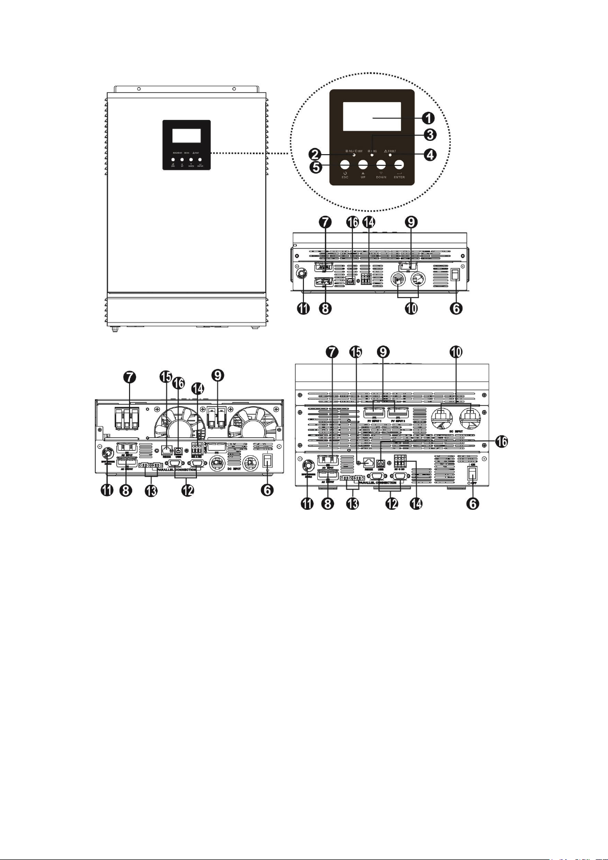
Product Overview
1KW/2KW
3KW/4KW 5KW
NOTE: For parallel model installation and operation, please check separate parallel installation guide for
the details.
1. LCD display 9. PV connectors
2. Status indicator 10. Battery connectors
3. Charging indicator 11. Circuit breaker
4. Fault indicator 12. Parallel communication cable
5. Function buttons 13. Current sharing cable
6. Power on/off switch 14. Dry contact
7. Grid connectors 15. RS-232 communication port
8. AC output connectors (Load connection) 16. USB communication port
3
INSTALLATION
Unpacking and Inspection
Before installation, please inspect the unit. Be sure that nothing inside the package is damaged. You should
have received the following items inside of package:
The unit x 1, User manual x 1, Communication cable x 1, Software CD x 1
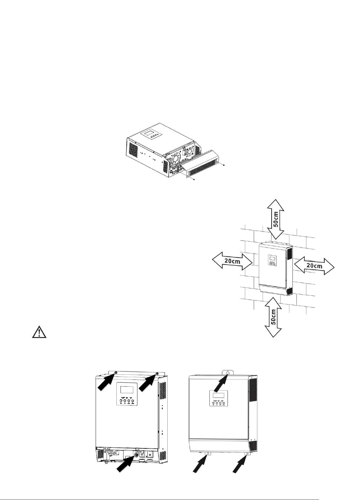
Preparation
Before connecting all wirings, please take off bottom cover by removing two screws as shown below.
Mounting the Unit
Consider the following points before selecting where to install:
Do not mount the inverter on flammable construction
materials.
Mount on a solid surface
Install this inverter at eye level in order to allow the LCD
display to be read at all times.
The ambient temperature should be between 0°C and 55°C
to ensure optimal operation.
The recommended installation position is to be adhered to
the wall vertically.
Be sure to keep other objects and surfaces as shown in the
right diagram to guarantee sufficient heat dissipation and
to have enough space for removing wires.
SUITABLE FOR MOUNTING ON CONCRETE OR
OTHER NON-COMBUSTIBLE SURFACE ONLY.
Install the unit by screwing three screws. It’s recommended to use M4 or M5 screws.
1KW-4KW model 5KW model
4
Battery Connection
Model
Typical
Amperage
Battery
Capacity
Wire Size
Ring Terminal
Torque
Value
Cable
mm2
Dimensions
D (mm)
L (mm)
1KW, 2KW,
3KW, 4KW
140A
200AH
1*2AWG
38
6.4
39.2
2~3 Nm
2*6AWG
28
6.4
33.2
5KW
180A
600AH
2*4AWG
44
10.5
55
10~12 Nm
WARNING: Shock Hazard
Installation must be performed with care due to high battery voltage in series.
CAUTION!! Do not place anything between the flat part of the inverter terminal and the ring
terminal. Otherwise, overheating may occur.
CAUTION!! Do not apply anti-oxidant substance on the terminals before terminals are connected
tightly.
CAUTION!! Before making the final DC connection or closing DC breaker/disconnector, be sure
positive (+) must be connected to positive (+) and negative (-) must be connected to negative (-).
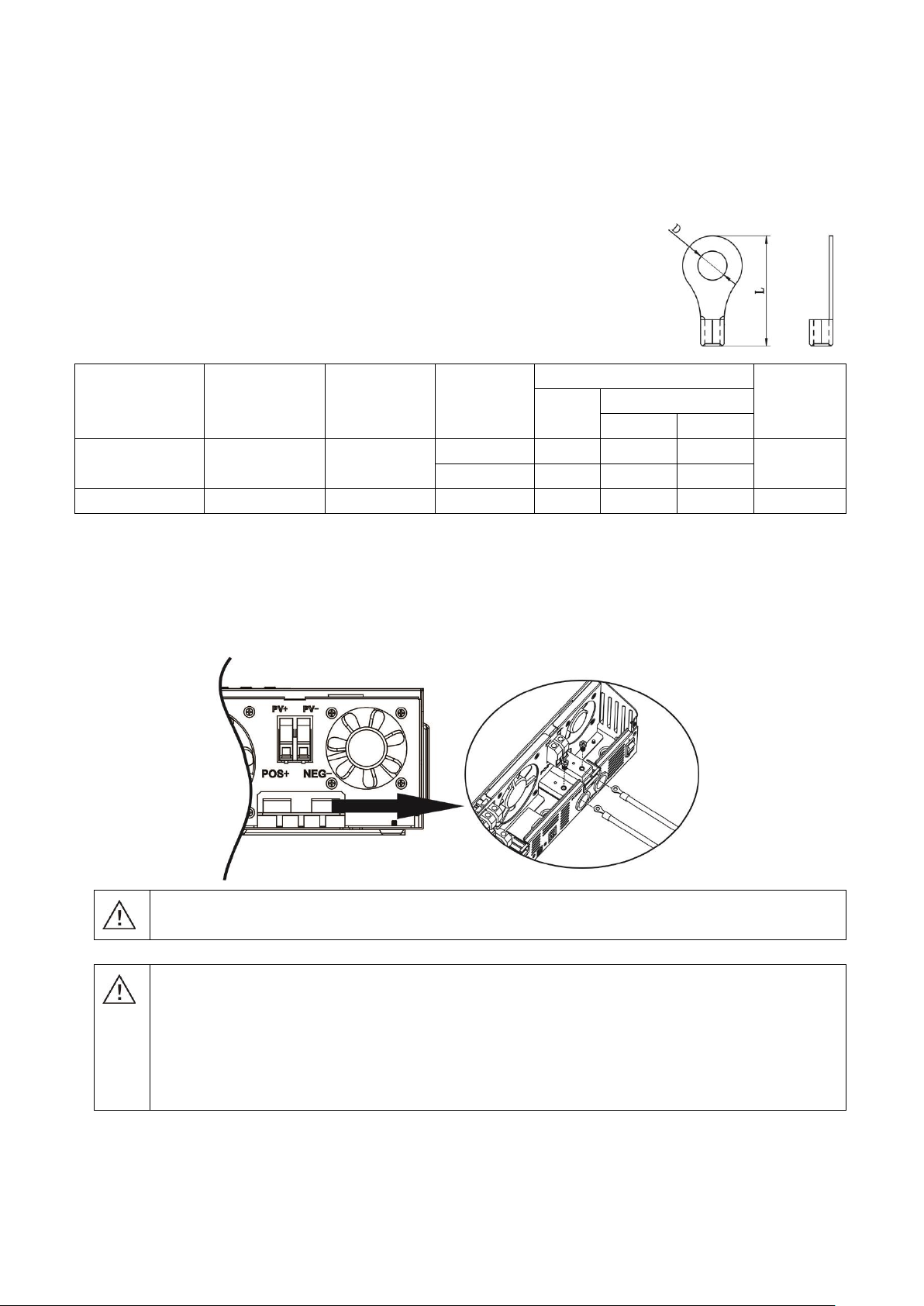
Ring terminal:
CAUTION: For safety operation and regulation compliance, it’s requested to install a separate DC over-current
protector or disconnect device between battery and inverter. It may not be requested to have a disconnect
device in some applications, however, it’s still requested to have over-current protection installed. Please refer
to typical amperage in below table as required fuse or breaker size.
WARNING! All wiring must be performed by a qualified personnel.
WARNING! It's very important for system safety and efficient operation to use
appropriate cable for battery connection. To reduce risk of injury, please use the
proper recommended cable and terminal size as below.
Recommended battery cable and terminal size:
Please follow below steps to implement battery connection:
1. Assemble battery ring terminal based on recommended battery cable and terminal size.
2. Insert the ring terminal of battery cable flatly into battery connector of inverter and make sure the bolts are
tightened with torque of 2-3 Nm. Make sure polarity at both the battery and the inverter/charge is correctly
connected and ring terminals are tightly screwed to the battery terminals.
5
AC Input/Output Connection
Model
Gauge
Torque Value
1KW
16 AWG
0.5~ 0.6 Nm
2KW
14 AWG
0.8~ 1.0 Nm
3KW
12 AWG
1.2~ 1.6 Nm
4KW
10 AWG
1.4~ 1.6Nm
5KW
10 AWG
1.4~ 1.6Nm
WARNING:
Be sure that AC power source is disconnected before attempting to hardwire it to the unit.
CAUTION!! Before connecting to AC input power source, please install a separate AC breaker between
inverter and AC input power source. This will ensure the inverter can be securely disconnected during
maintenance and fully protected from over current of AC input.
CAUTION!! There are two terminal blocks with “IN” and “OUT” markings. Please do NOT mis-connect input
and output connectors.
WARNING! All wiring must be performed by a qualified personnel.
WARNING! It's very important for system safety and efficient operation to use appropriate cable for AC input
connection. To reduce risk of injury, please use the proper recommended cable size as below.
Suggested cable requirement for AC wires
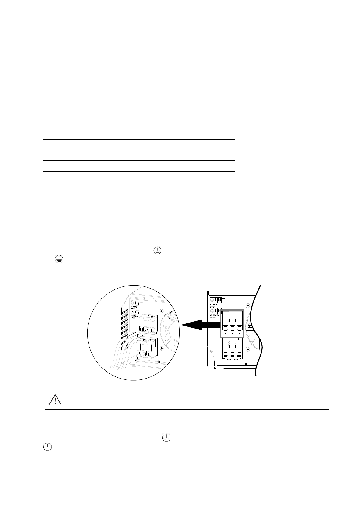
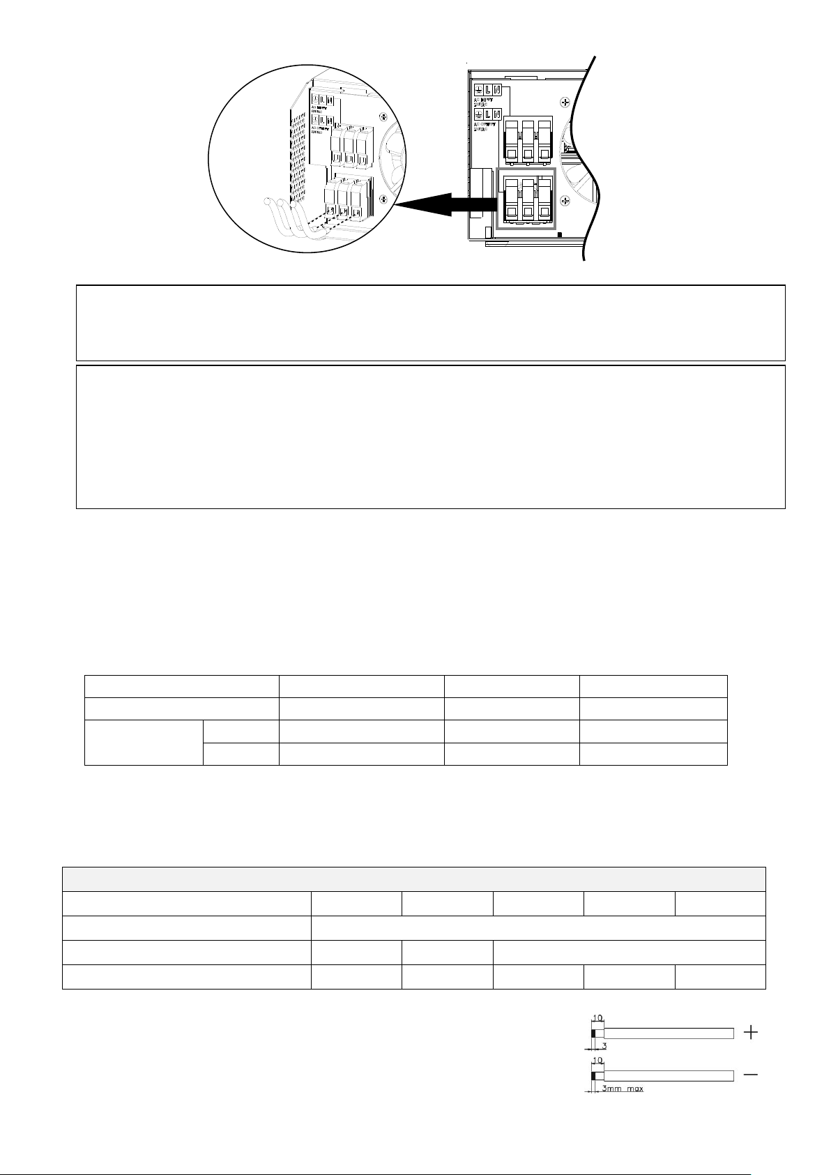
Please follow below steps to implement AC input/output connection:
1. Before making AC input/output connection, be sure to open DC protector or disconnector first.
2. Remove insulation sleeve 10mm for six conductors. And shorten phase L and neutral conductor N 3 mm.
3. Insert AC input wires according to polarities indicated on terminal block and tighten the terminal screws. Be
sure to connect PE protective conductor ( ) first.
→Ground (yellow-green)
L→LINE (brown or black)
N→Neutral (blue)
4. Then, insert AC output wires according to polarities indicated on terminal block and tighten terminal screws.
Be sure to connect PE protective conductor ( ) first.
→Ground (yellow-green)
L→LINE (brown or black)
N→Neutral (blue)
6
Model
Typical Amperage
Cable Size
Torque
1KW, 2KW, 3KW, 4KW
80A
6AWG
2.0~2.4Nm
5KW
PV 1
60A
8AWG
2.0~2.4Nm
PV 2
60A
8AWG
2.0~2.4Nm
Solar Charging Mode
INVERTER MODEL
1KW
2KW
3KW
4KW
5KW
Max. PV Array Open Circuit Voltage
145Vdc
PV Array MPPT Voltage Range
15~115Vdc
30~115Vdc
60~115Vdc
MPP Number
1 1 1 1 2
CAUTION: Important
Be sure to connect AC wires with correct polarity. If L and N wires are connected reversely, it may cause
utility short-circuited when these inverters are worked in parallel operation.
CAUTION: Appliances such as air conditioner are required at least 2~3 minutes to restart because it’s required
to have enough time to balance refrigerant gas inside of circuits. If a power shortage occurs and recovers in a
short time, it will cause damage to your connected appliances. To prevent this kind of damage, please check
manufacturer of air conditioner if it’s equipped with time-delay function before installation. Otherwise, this
inverter/charger will trig overload fault and cut off output to protect your appliance but sometimes it still causes
internal damage to the air conditioner.
5. Make sure the wires are securely connected.
PV Connection
CAUTION: Before connecting to PV modules, please install separately a DC circuit breaker between inverter
and PV modules.
WARNING! All wiring must be performed by a qualified personnel.
WARNING! It's very important for system safety and efficient operation to use appropriate cable for PV
module connection. To reduce risk of injury, please use the proper recommended cable size as below.
PV Module Selection:
When selecting proper PV modules, please be sure to consider below parameters:
1. Open circuit Voltage (Voc) of PV modules not exceeds max. PV array open circuit voltage of inverter.
2. Open circuit Voltage (Voc) of PV modules should be higher than min. battery voltage.
Please follow below steps to implement PV module connection:
1. Remove insulation sleeve 10 mm for positive and negative conductors.
2. Check correct polarity of connection cable from PV modules and PV input
connectors. Then, connect positive pole (+) of connection cable to positive
pole (+) of PV input connector. Connect negative pole (-) of connection
cable to negative pole (-) of PV input connector.
7
 Loading...