

Infinique INB718Z-RATS Quick Installation Manual
1
Quick Installation Guide
This manual provides instructions for quick installation and basic configuration of your IP device.
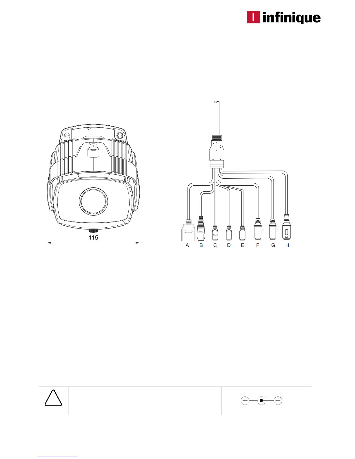
Step1. Connect cables to IP device
Connect required cables to the device including the power cable, LAN cable, and other optional
cables. To see the correct positions of all connectors, refer to the following image below.
A. Ethernet Port [PoE]
B. Composite Video Out
C. RS485 Port
D. Alarm Output
E. Alarm Input
F. Audio Out
G. Audio In
H. DC Power
Make sure the polarity is correct. Incorrect connection
may cause malfunction or damage to the IP device.
Caution
!
Power Adaptor Connector (DC 12V)
* Models herein and their appearance are subject to change without any prior notice.
2
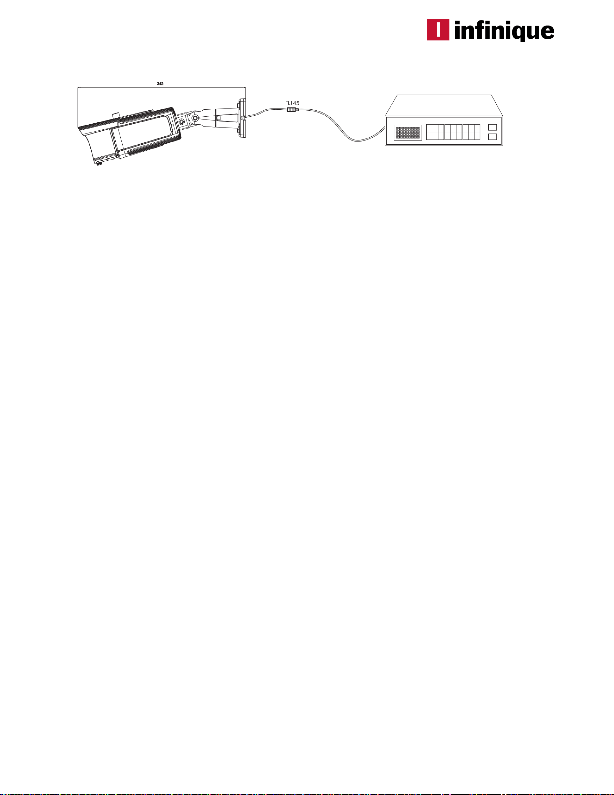
Step2. Install IP device
Step3. Set up network environment
The default IP address of your IP device is 192.168.0.100. You can find the available IP address from
the MAC address of your device. Please make sure the device and your PC are on the same
network segment before running the installation. If the network segment was different between your
PC and the device, change your PC’s settings as below.
IP address : 192.168.0.xxx
Subnet mask: 255.255.255.0
1) Drill holes in correct positions and insert anchor blocks into the holes.
2) Place the camera body to the installation surface and match alignment holes with the
anchor blocks. Then tighten the surface anchor studs.
3) Connect all the required cables to the camera.
4) Adjust the camera to the desired angle by unscrewing the joints.
6) Once properly placed, tighten the screws.
7) The camera can be ceiling mounted or wall mounted depending on the environment
and safety, aesthetic aspects.
NOTE. When you want to check the video output on an analog monitor at the installation
site, make sure to set the output configuration switch to NTSC or PAL according to the
video standard.
 Loading...