

Infinique IHR16-12F2I-S, IHR8-12F2I-S, IHR4-12F1I-S, IHR16-24H1I-S, IHR8-12H1I-S Operating Instructions Manual
...
AHD Digital Video Recorders
Operating Instructions
Premium Series Model Numbers
IHR4-12H1I-S 4 Channel 720p DVR
IHR8-12H1I-S 8 Channel 720p DVR
IHR16-24H1I-S 16 Channel 720p DVR
IHR4-12F1I-S 4 Channel 1080p DVR
IHR8-12F2I-S 8 Channel 1080p DVR
IHR16-12F2I-S 16 Channel 1080p DVR
Before attempting to connect or operate this product, read the instructions carefully and save
this manual for future use.
RoHS

2 TEC-VS-219-1605-V01
Important Safety Instructions
Please carefully read the following safety instruction to avoid personal injuries and prevent the
equipment and other connected devices from being damaged.
Power sources (note: please use the power supply included or as specified by the
manufacturer). Never operate the equipment by using unspecified power supply.
Never push objects of any kind through openings of DVR to avoid electric shock or other
accidents.
Do not place the equipment in dusty environment. Do not install the DVR in places that are
prone to dust.
Do not place the equipment under rain or humid environment like basement. If the
equipment is accidentally in contact with water, unplug the power cable and immediately
contact your local dealer.
Do not install near any heat sources such as radiators, heat registers, or other apparatus
that produce heat.
Keep the surface of the equipment clean and dry. Use soft damp cloth to clean the outer
case of DVR (do not use liquid aerosol cleaners).
Do not operate if any problems are found. If there are any strange smell or sounds from
DVR, unplug the power cable and contact the authorized dealer or service center.
Do not try to remove the upper cover. Warning: Do not remove the cover of DVR to avoid
electric shock.
Handle with care. If DVR does not work normally because of damage caused by dropping
or mishandling, please contact the authorized dealer for repairs. Note: Warranty is void in such
cases.
Use standard lithium battery (Note: Use the batteries included or as specified by the
manufacturer). After cutting off the power supply, if the system clock does not work, please
replace the standard 3V lithium battery on the main board. Warning: Turn off DVR before
replacing the batteries, or you may suffer from serious electric shock. Please properly dispose
the used batteries as per local regulations.
Place the DVR equipment in a place with good ventilation. The DVR system includes HDD,
which produces large amount of heat during operation. As a result, do not block the ventilation
openings (on the top, bottom, both sides and the reverse side) for cooling the system during
operation. Install or put the equipment in the place with good ventilation. The attached power
adapter can only be used for one set of DVR. Do not connect more equipment, or DVR may
restart repeatedly because of insufficient power.
Protect the power cord from being walked on or pinched particularly at plugs,
convenience receptacles, and the point where they exit from the apparatus.
Unplug this apparatus. When a cart is used, use caution when moving the cart/apparatus
combination to avoid injury from tip-over.
Prevent the equipment from water dropping or splashing. Do not place objects containing
water, such as flower vase, on the equipment.

TEC-VS-219-1605-V01
TO REDUCE THE RISK OF ELECTRIC SHOCK, DO NOT REMOVE.
NO USER-SERVICEABLE PARTS INSIDE. REFER SERVICING TO QUALIFIED SERVICE PERSONNEL ONLY.
.
FCC For Class-A Digital Device
A CLASS-A digital device complies with Parts 15 of the FCC Rules.
Operation is subject to the following two conditions.
This device may not cause harmful interference.
This device must accept any interference received, including interference that may cause undesired
operations.
The lightning flash with an arrowhead symbol within an equilateral triangle is
intended to alert the user to the presence of un-insulated “dangerous voltage”
within the product’s enclosure that may be of sufficient magnitude to constitute a
risk of electric shock to persons.
The exclamation point within an equilateral triangle is intended to alert the user to
presence of important operating and maintenance (servicing) instructions in the
literature accompanying the appliance

2 TEC-VS-219-1605-V01
Table of Contents
Important Safety Instructions ............................................................................................................ 2
1. Introduction .................................................................................................................................. 4
1.1 Features ......................................................................................................................................... 4
2. DVR Overview ................................................................................................................................ 5
2.1 Front Panel ..................................................................................................................................... 5
2.2 Rear Panel ...................................................................................................................................... 6
2.2.1 Rear panel for DVR with 4/8 Channel DVR .............................................................................. 6
2.2.2 Rear panel for DVR with 16 Channel DVR ............................................................................... 7
2.3 Remote Controller ......................................................................................................................... 7
3. DVR Connections .......................................................................................................................... 8
3.1 HDD Installation .............................................................................................................................. 8
3.2 Camera and Monitor Connection ................................................................................................ 8
3.3 Power Supply Connection.............................................................................................................. 8
4. DVR Boot Up .................................................................................................................................. 9
4.1 System Initialization ........................................................................................................................ 9
4.2 Startup Wizard ................................................................................................................................ 9
4.3 Main Interface ............................................................................................................................. 11
5. DVR Menu ................................................................................................................................... 12
5.1 Main Menu Guide ........................................................................................................................ 13
5.2 Main Menu ................................................................................................................................... 14
5.2.1 Parameter ............................................................................................................................. 14
5.2.1.1 Analog Channels ........................................................................................................... 14
5.2.1.2 IP Channels .................................................................................................................... 15
5.2.1.3 Live ................................................................................................................................. 16
5.2.1.4 Output ............................................................................................................................ 17
5.2.1.5 Privacy Zone ................................................................................................................... 17
5.2.1.6 Record ........................................................................................................................... 18
5.2.1.7 Record Schedule ........................................................................................................... 19
5.2.1.8 Mainstream .................................................................................................................... 19
5.2.1.9 Substream ...................................................................................................................... 20
5.2.1.10 Mobilestream ............................................................................................................... 21
5.2.1.11 Capture ........................................................................................................................ 21
5.2.1.12 Capture Schedule ....................................................................................................... 22
5.2.1.13 Network ........................................................................................................................ 23
5.2.1.14 E-mail ........................................................................................................................... 23
5.2.1.15 E-mail Schedule ........................................................................................................... 24
5.2.1.16 DDNS ............................................................................................................................ 25
5.2.1.17 RTSP .............................................................................................................................. 26
5.2.1.18 FTP ................................................................................................................................ 26

3
5.2.1.19 Motion .......................................................................................................................... 27
5.2.1.20 Alarm ............................................................................................................................ 28
5.2.2 Record Search ...................................................................................................................... 29
5.2.2.1 General .......................................................................................................................... 29
5.2.2.2 Time Axis Setup, File Clip and Zoom In/Out ................................................................... 31
5.2.2.3 Events ............................................................................................................................. 33
5.2.2.4 Quick Backup and Backup ............................................................................................ 33
5.2.2.5 Play Backup Files ............................................................................................................ 34
5.2.3 Device ............................................................................................................................... 35
5.2.3.1 HDD ................................................................................................................................ 35
5.2.3.2 PTZ Camera Setup ......................................................................................................... 37
5.2.3.3 Cloud ............................................................................................................................. 37
5.2.4 System ................................................................................................................................... 39
5.2.4.1 General .......................................................................................................................... 39
5.2.4.2 DST .................................................................................................................................. 40
5.2.4.3 NTP.................................................................................................................................. 40
5.2.4.4 Users ............................................................................................................................... 41
5.2.4.5 User Edit .......................................................................................................................... 42
5.2.4.6 Info ................................................................................................................................. 43
5.2.4.7 Log ................................................................................................................................. 43
5.2.5 Advanced ............................................................................................................................. 44
5.2.5.1 Maintain ......................................................................................................................... 44
5.2.5.2 Events ............................................................................................................................. 45
5.2.7 Shutdown .............................................................................................................................. 45
5.3 Menu Lock ................................................................................................................................... 46
5.4 Display Layout .............................................................................................................................. 46
5.5 Record Search ............................................................................................................................. 46
5.6 Mute ............................................................................................................................................. 47
5.7 Start Sequence ............................................................................................................................ 47
6. Web Application Manager ......................................................................................................... 48
6.1 ActiveX control download and installation .................................................................................. 48
6.2 Web Application Manager Login ................................................................................................. 49
6.3 Live Mode .................................................................................................................................... 49
6.3.1 Menu Bar ............................................................................................................................... 50
6.3.1.1 Live Display ..................................................................................................................... 50
6.3.1.2 Video Control ................................................................................................................. 51
6.3.2 Playback ............................................................................................................................... 51
6.3.2.1 Record Search ............................................................................................................... 52
6.3.2.2 Playback Control ............................................................................................................ 53
6.3.3 Remote Setting ..................................................................................................................... 55

4 TEC-VS-219-1605-V01
1. Introduction
Infinique’s Premium series AHD Digital Video Recorder offers a wide range of recording solutions for
AHD based video surveillance that are extremely easy to install, use and maintain. The hardware is
optimized for video surveillance by consolidating disparate components into a single chassis, which is
energy efficient and greatly improves the total cost of ownership. From a small to large installations,
Infinique’s Analog HD video recorders are an ideal solution for today’s high demanding video
surveillance needs.
Infinique’s AHD series DVRs are designed with feature rich capability that takes an advantage of H.264
video compression technology to dramatically reduce the amount of storage and bandwidth while
producing excellent image quality. Its high-end features include real multiplex operations, higher
storage capacity, and faster frame rate with 1080P high-resolution recording and built-in web server
for remote monitoring and administration. The dual stream feature provides simultaneous high quality
streams each for recording and remote monitoring. It facilitates users to view, record, playback,
back up video and remotely control the system with its user friendly operation interface button panel.
Continuous, Manual, Motion detection recording are supported by our AHD Series DVRs.
Designed as a full-fledged device this DVR works with three types of video cameras viz., Standard
analog D1/960H, AHD and IP, thus allowing to connect already installed IP/ Standard analog video
cameras to AHD Video recorders, It also comes with HDMI, VGA, USB and Ethernet ports. The DVR has
an internal SATA HDD of high recording capacity for large storage requirements. This plug-n-play HD
Series DVRs is a versatile choice with effortless installation, minimum maintenance and low operational
cost. Mainly suitable for small to mid-sized installations such as retail shops, offices, hotels, banks,
warehouses etc.
1.1 Features
Hybrid DVR supporting Analog, AHD and IP cameras
Real time recording @ 720P/1080P
True Multiplex Operation
Supports H.264 high profile Compression
Multiple recording options: Continuous, Manual, Motion detection
Backup via USB, HDD and Network
Dual Streaming (Local Recording and Network Transmission)
Mobile app for Android and iOS
Cloud storage on Dropbox
Email Notification of events
5
2. DVR Overview
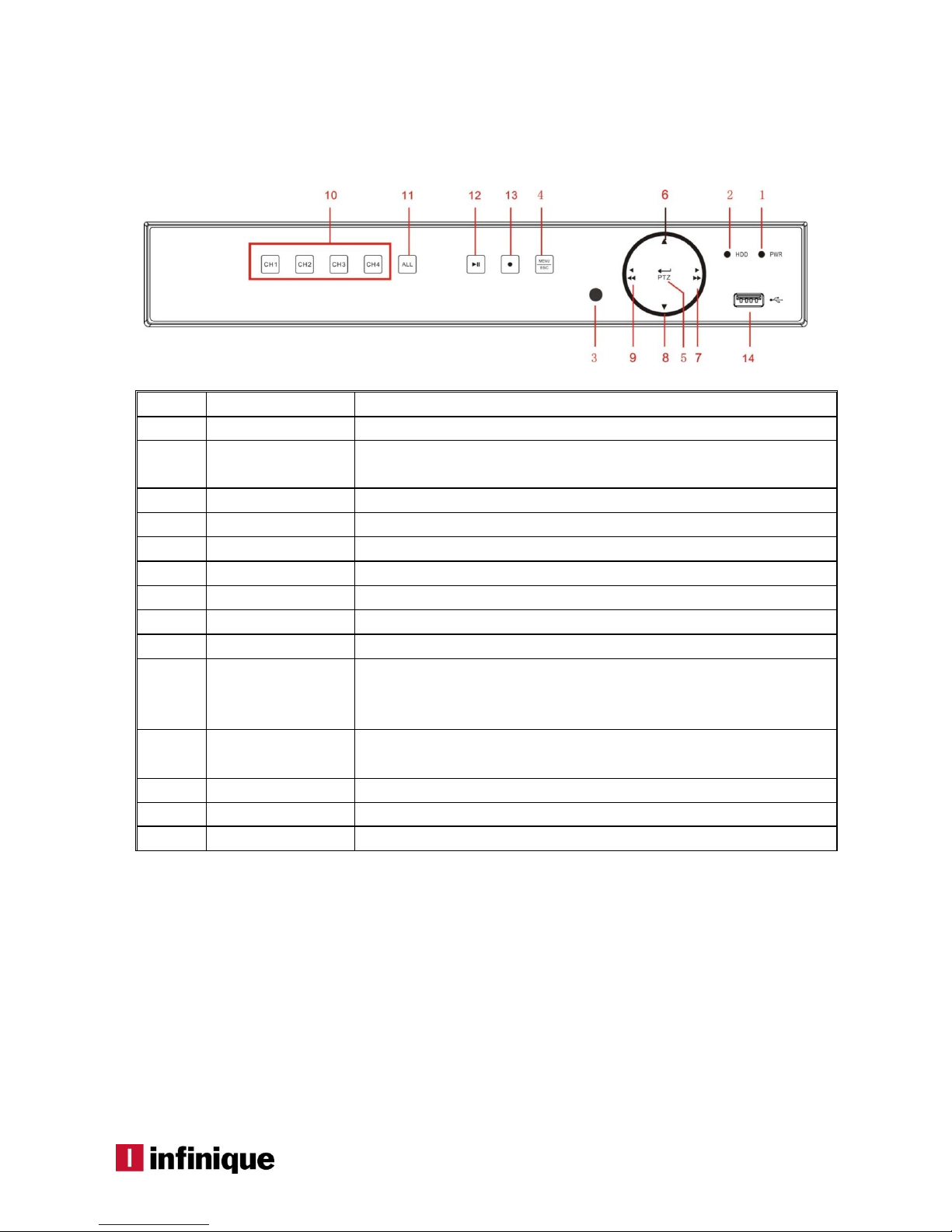
2.1 Front Panel
(For reference only, design subjected to change without prior notice)
SN
Key or Indicator
Functions
1
Power Indicator
The “Green” indicator shows that the DVR is powered ON.
2
HDD Indicator
The “Red” flashing indicator shows that the hard drive is being read or
written to.
3
IR Port
Receives IR signal from Remote Controller.
4
MENU/ESC
To enter/exit the Main menu
5
PTZ
Enter into PTZ control interface
6
Up key
Move up
7
RIGHT/FWD
Right key& Fast forward
8
Down key
Move down
9
LEFT/REW
Move to left& Rewind function
10
Channel select:
CH1 CH2
CH3 CH4
Single channel selection(4-Channel DVR)
11
ALL
Display All channels in split view display layout
12
QUAD
On Live or Playback mode, switch to Quad display.
13
PLAY/PAUSE
Play / pause the video
14
USB
USB port to connect mouse
6 TEC-VS-219-1605-V01
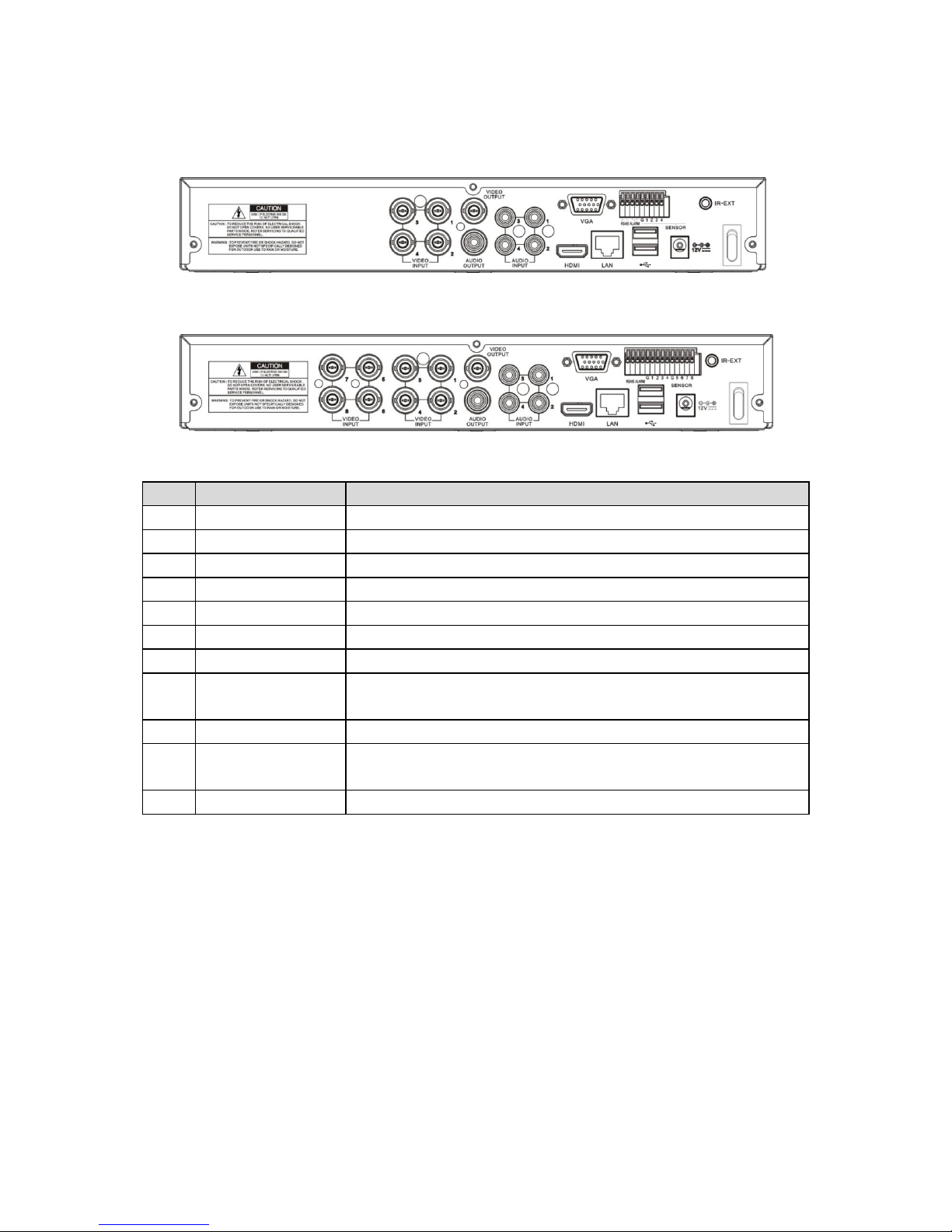
2.2 Rear Panel
2.2.1 Rear panel for DVR with 4/8 Channel DVR
(For reference only, design subjected to change without prior notice)
SN
Physical Interface
Function
1
Video Input
To connect CH1-4 (analog) video input devices, standard BNC port
2
Video Output
To connect monitor display output , standard BNC port
3
Audio Input
To connect CH1-4 audio input signals (microphone), RCA port
4
Audio Output
Audio signal output to connect speakers, RCA port
5
USB Port
To connect USB storage devices
6
USB Mouse Port
To connect USB mouse
7
VGA Port
To connect VGA displays, such as a PC monitor
8
RS-485/Sensor/Alarm
RS485/Sensor/Alarm port. Connect by referring to the interface
definition below
9
Power Port
To connect a power supply DC12V 3A, supplied with the DVR
10
LAN Port
To connect to a Local Area Network (LAN), standard Ethernet or RJ45
port.
11
Power Switch
Turn on /off power supply

7
2.2.2 Rear panel for DVR with 16 Channel DVR
(For reference only, design subjected to change without prior notice)
SN
Physical Interface
Function
1
Video input
To connect CH1-16 (analog) video input devices, standard
RCA port
2
Video output
To connect to a (upper) Main monitor; (lower) SPOT out monitor
3
Audio input
To connect CH1-16 audio signal inputs (microphone), RCA port
4
Audio output
To connect to a Speaker, RCA port
5
LAN: Network port
To connect to a LAN, standard Ethernet or RJ45 port.
6
RS-485/Sensor/Alarm
RS485/Sensor/Alarm port. Connect by referring to the interface
definition below
7
Power Switch
Turn on/off power supply
8
VGA port
To connect to a VGA display, such as PC monitor
9
HDMI port
To connect to a HDMI high definition display
10
USB mouse port
To connect to a USB mouse
11
Power port
To connect a power supply DC12V 5A, supplied with the DVR
2.3 Remote Controller
Table 2-3 Operation of remote controller
SN
Buttons
Functions
1
1-8
Channel1-8; Numerical Key
2
9, 0
Numerical Key
3
ALL
Multi-Channel Display
4
Menu
To enter into Main Menu/Return
5 ▲ Move UP; Volume adjustment
6 ▼ Move DOWN; Volume adjustment
7
/
Move LEFT/RIGHT; Decrease/increase
parameter value on the control bar
8
SEL
Select/Edit; Confirm the selection
9 Fast Backward
10 Enter into Record Search Menu; Play
11 Fast Forward
12 ● Record Key
13 Pause/Sequence Key
14 ■ Stop Manual Recording; Stop Playing
15
Audio
To test audio
16
Mute
Mute ON/OFF
Table 2-3

8 TEC-VS-219-1605-V01
3. DVR Connections
3.1 HDD Installation
Caution: Please do not take out hard drive when DVR is powered ON!
(1) Disconnect the power, and then remove screws on the sides and rear to open DVR upper cover.
(2) Connect the data and power connectors of the SATA cable to the main board. Install the HDD to fix
it on the bracket and then connect the installed SATA cable to HDD power and the data lines.
(3) Install the upper cover back carefully and put back the screws that were removed earlier.
Note: It is strongly recommended to use special hard drives designed for video surveillance
applications.
3.2 Camera and Monitor Connection
DVR video output signals are transmitted to a VGA monitor or HDMI monitor by VGA or HDMI cable.
3.3 Power Supply Connection
Please use the supplied power adapter to connect DVR. Before powering on, make sure the cables on the
audio and video I/O ports and network port are connected.
9
4. DVR Boot Up
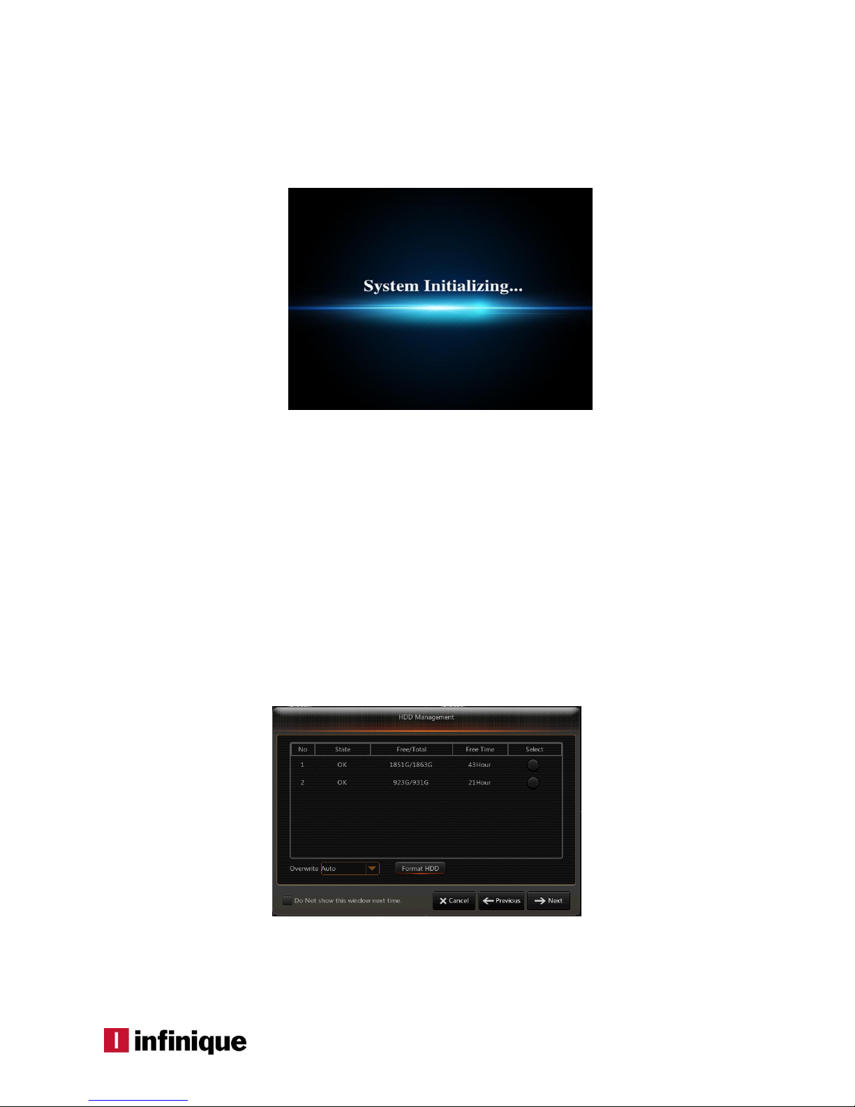
4.1 System Initialization
After connecting the power cable of DVR to a power outlet, Press the power button to boot the DVR.
The system initializing screen will be displayed as shown in Picture 4-1.
Picture 4-1
Note:The illustrations shown in user manual may not be the same as the menu interface. All the
illustrations are only for user’s reference
4.2 Startup Wizard
After DVR startup is completed, the startup wizard will be displayed. To avoid the startup wizard from
appearing again, click “Don't show this window next time”, as shown in Picture 4-2.
This wizard includes the HDD management, Network configuration, IPC Setup, Record Schedule and
General System configuration.
The HDD Management page (Picture 4-2) allows the users to format the HDD and also to set the
overwrite mode when it is full.
Picture 4-2
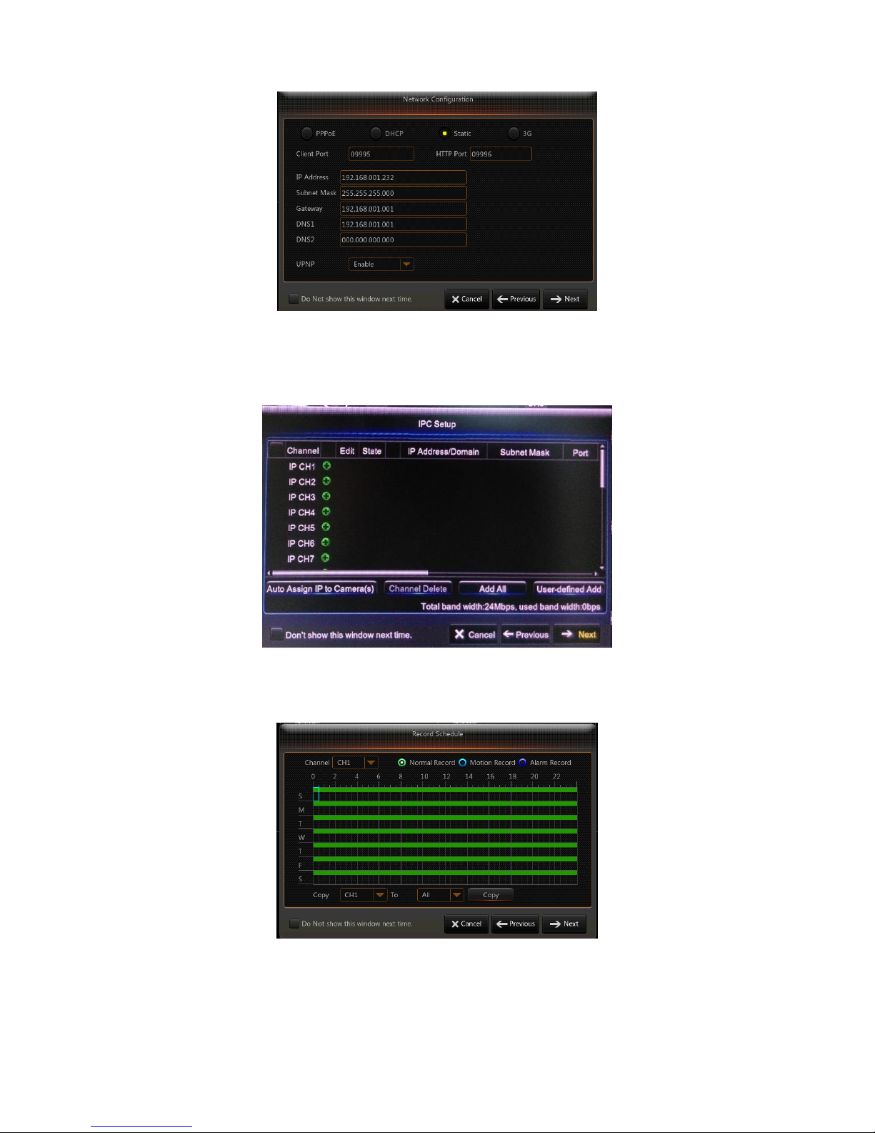
The Network Configuration page allows the user to set the network environment of the DVR, as shown in
Picture 4-3
10 TEC-VS-219-1605-V01
Picture 4-3
The IPC setup page allows the users to add and delete IP cameras.
Picture 4-4
The Recording schedule page allows the users to set recording time and scheduled recording of DVR.
Picture 4-5
The General System Configuration page allows the users to set the general system parameters.
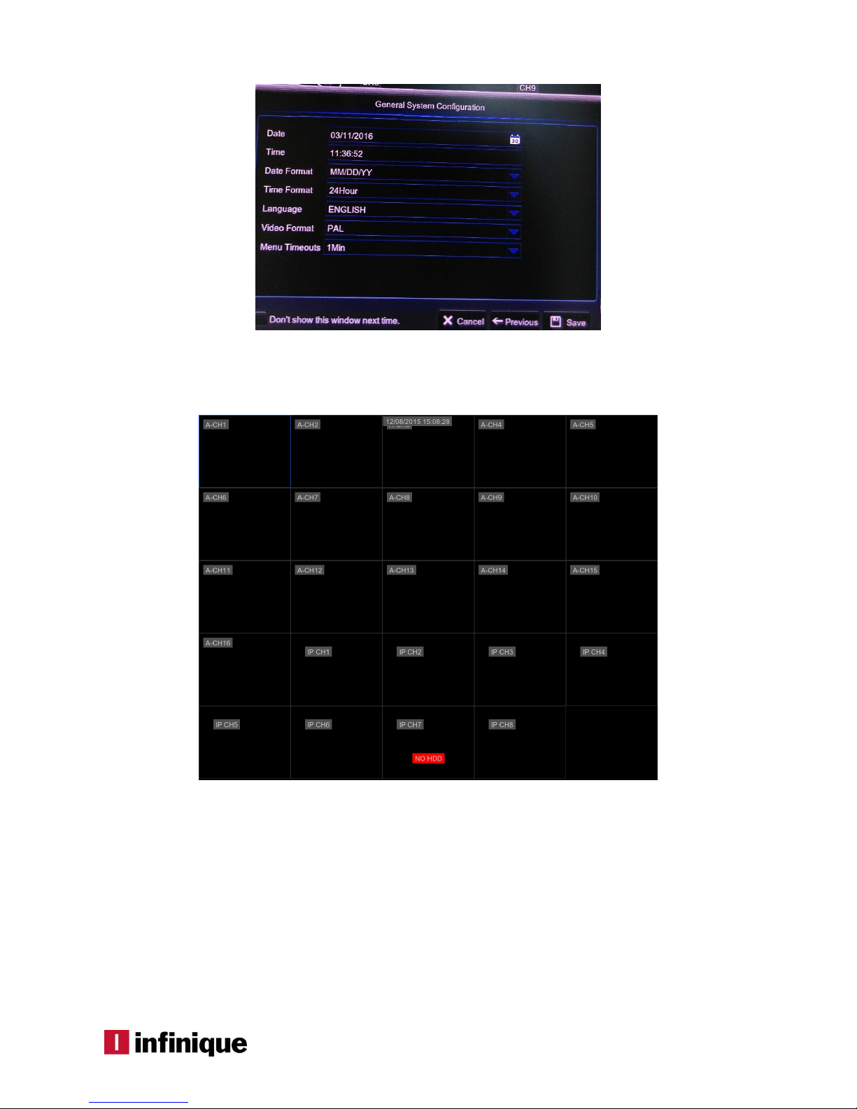
11
Picture 4-6
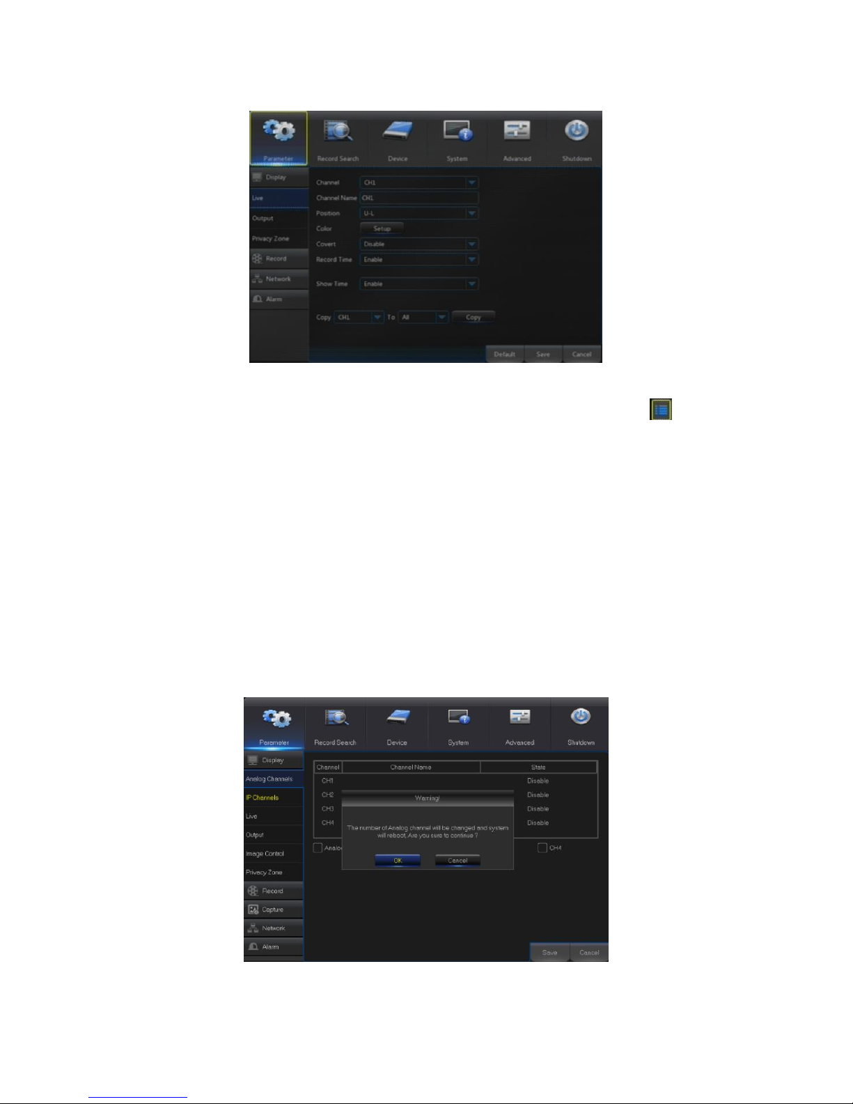
4.3 Main Interface
Picture 4-7
Note: When internal HDD is not connected to DVR, “NO HDD” message will appear on the lower part of
the main interface and a buzzer alarm is heard.
To disable the buzzer alarm, Go to Menu ->Event ->Alarm and disable HDD loss alarm, HDD space
insufficiency alarm and set alarm output to “off”.

12 TEC-VS-219-1605-V01
5. DVR Menu
Popup Menu
After the system initialization, right click the mouse on preview interface or slide the mouse to the
bottom of screen to enter into Pop-up Menu. Using this option, Main Menu, Multi-screen, Auto Cruise,
Record Search, Sequence, Volume and Brightness setting can be configured, as shown in Picture 5-1.
The options in the pop-up menu may vary slightly according to different parameter settings and
application environment. The options in the menu will be explained in detail in the following chapters.
Picture 5-1

13
5.1 Main Menu Guide
Display
Analog
Channels
IP Channels
System
Live
Output
Record
Network
Shutdown
Main Menu
Private Zone
Parameter
Network
Record
Alarm
Record
Event Search
Device
General
Users
Info
Log
Schedule
Mainstream
FTP
Email
Substream
Email
DDNS
RTSP
Motion
Alarm
Record
HDD
PTZ
Cloud
Advanced
Intelligent
Maintenance
Events
DST
General
NTP
14 TEC-VS-219-1605-V01
5.2 Main Menu
Picture 5-2
In LIVE mode, click the mouse button, or [Menu] button on the remote controller, or click [ ] icon on
the toolbar to enter the main menu screen, as shown in Picture 5-2.
If system interface is locked, refer to section 5.3 to unlock by entering the password
In Main Menu mode, settings for Parameter, Record Search, Device, System, Advanced and Shutdown
can be configured.
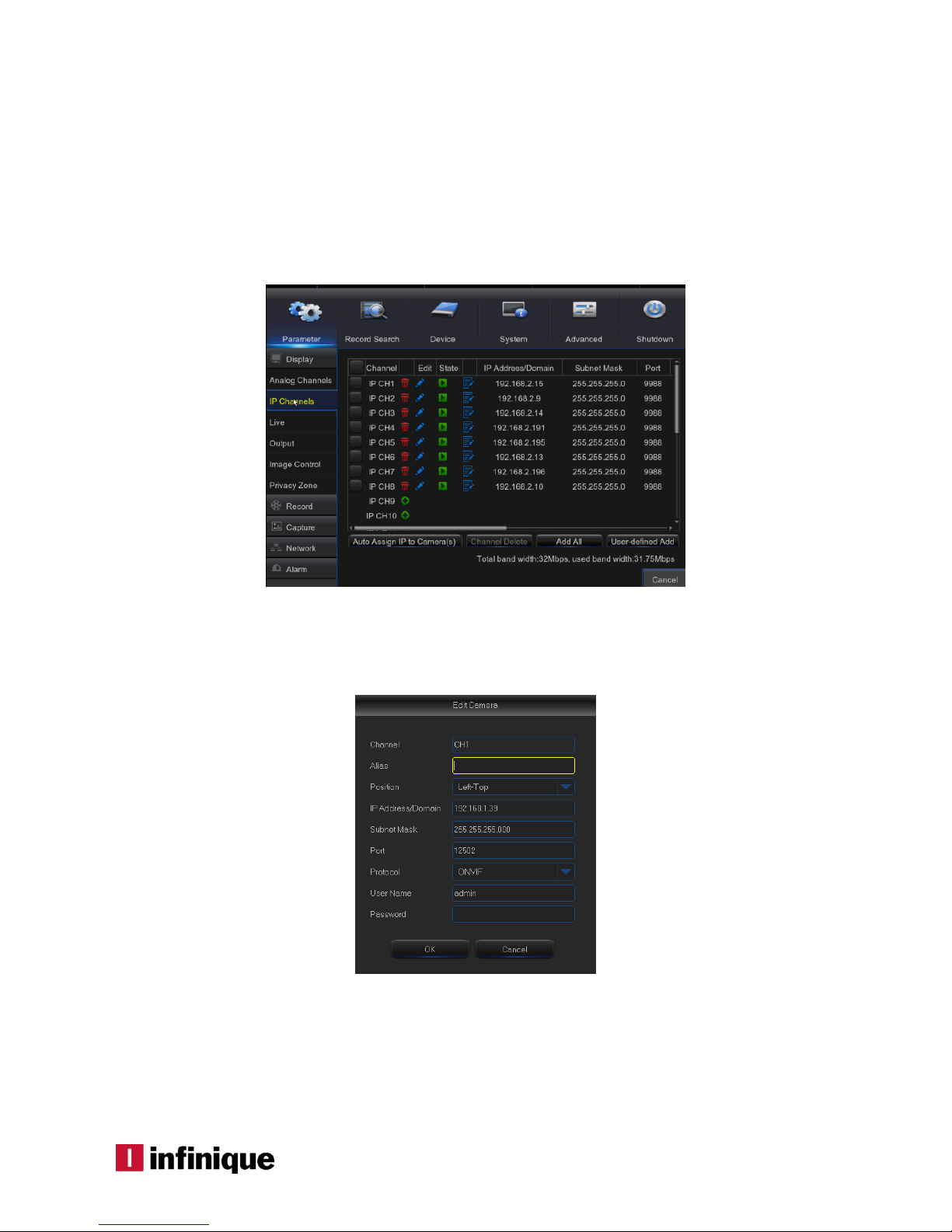
5.2.1 Parameter
5.2.1.1 Analog Channels
Go to “Main Menu”“Parameter”“Display”“Analog Channels” to enter into the menu shown in
Picture 5-3.
This menu allows the users to choose which of the channels of the DVR is to be configured as Analog
channels.
Picture 5-3
15
Select the channels and click on save button. The DVR will reboot to apply the changes.
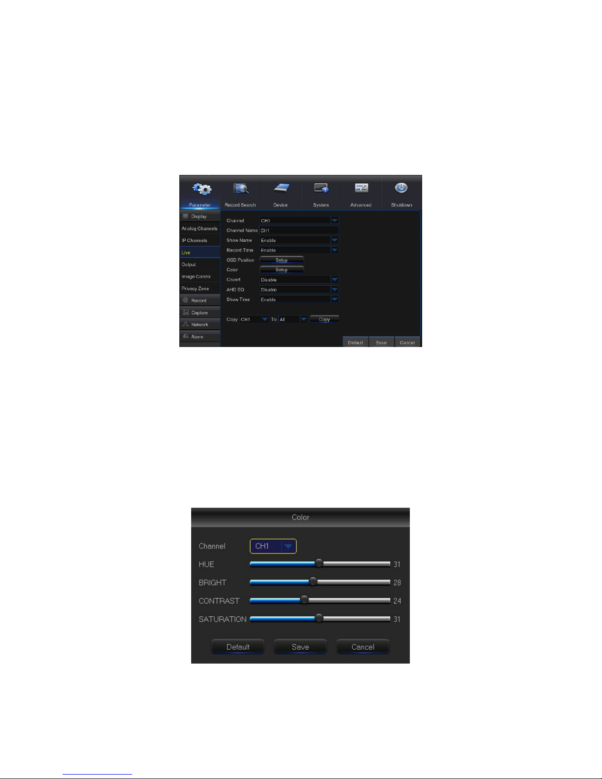
5.2.1.2 IP Channels
Go to “Main Menu” “Parameter” “Display” “IP Channels” to enter into the menu shown in
Picture 5-4.
This menu allows the users to configure the IP channels of the DVR.
Picture 5-4
Channel : Select Camera channel
Edit:Used to Rename, change the channel position and protocols of IP camera as shown below
Picture 5-5
Status:Displays IP Camera status
IP Address/Domain: IP address of the IPC connected of the channel
Subnet Mask:IP camera subnet mask
Port:Connection port number of the currently connected IP Camera.
16 TEC-VS-219-1605-V01
Manufacturer:Manufacturer information of the IP Camera.
Device type: Type of the device connected
Protocol: The selected access protocol for camera to connect to NVR
MAC Address:Physical address for the device
Software:Displays current version of IP Camera.
5.2.1.3 Live
Picture 5-6
Channel: Select the channel in the drop-down list.
Channel Name: Channel name, supports up to 8 characters.
Show Name: Show the channel name
Record Time: Burn the time information in the recorded video
OSD Position: Set the position for the OSD.
Color: Click “Setup” to enter into the color setup page (Picture 5-4)
Covert: Enable or Disable the channel for real-time monitoring
Show Time: Enable or Disable the system time display in the live monitoring.
Copy: Copy the parameters of the selected channel to any other or all channels.
Picture 5-7
In the color, setup window, adjust the brightness, hue, contrast and saturation of the image in the
selected channel, which is in “Live” mode.

17
Note:Click Default to set the default color settings.
5.2.1.4 Output
Go to “Main Menu”“Parameter”“Display”“Output” to enter into the menu shown in Picture 5-8.
Picture 5-8
Video Output: Select the video output mode
SeqMode : Select the layout for the sequence mode
SEQ Dwell Time: Sequence time is set 5 secs by default. User may change this as required
VGA/HDMI Resolution: Select the resolution for the video output. The available resolutions are
800×600, 1024×768, 1280×1024, 1440×900, 1280×720, 1920×1080
Transparency: Adjust menu transparency in the range of 0~128.
Support Over scan: Check to support HDMI Over scan
5.2.1.5 Privacy Zone
Go to “Main Menu”“Parameter”“Display ”“Privacy Zone” to enter into the menu shown as in
Picture 5-6.
Privacy Zone is for masking areas in the selected channel, as shown in Picture 5-9 and Picture 5-10.
1. Select the number of the zone to be set (maximum four zones can be set for a channel).
2. Click “Setup” to adjust the position of the zone.
3. After finish setting, right click the mouse to return to the “Privacy Zone” page.
4. Click “Save” to save the setting.

18 TEC-VS-219-1605-V01
Picture 5-9
Picture 5-10
5.2.1.6 Record
Go to “Main Menu”“Parameter”“Record”“Record” to enter into the menu shown in Picture 5-11.
Picture 5-11

19
Channel: Set the desired channel from the drop-down menu
Record Switch: Enable/Disable record
Pre Record: Enable to pre-record motion
Steam Mode: Select the stream, which has to be used for recording for this particular channel.
5.2.1.7 Record Schedule
Go to “Main Menu”“Parameter”“Record”“Record Schedule” to enter into the Record Schedule menu
to set record schedule for the DVR, as shown in Picture 5-12.
Picture 5-12
Select the channel and select the type of capture i.e., Normal, Motion or Alarm
The record schedule can be set for the whole week and the schedule of the current channel can
be copied to any other channel or all channels to speed up the scheduling process.
Note:
1. In the Record schedule menu, “No Color ” stands for no recording;
2. “Green” stands for Normal capture
3. “Yellow” stands for Motion capture
4. “Red” stands for Alarm capture
5.2.1.8 Mainstream
Go to “Menu”“Parameter”“Record”“Mainstream” to enter into the menu interface, as shown in
Picture 5-13.

20 TEC-VS-219-1605-V01
Picture 5-13
Channel: Select the channel
Resolution: Supports three kinds of resolution: 960H/720P/1080P.
FPS:PAL: 1~25fps; NTSC: 1~30fps.
Bitrate Control: Select the bitrate control method. The available options are CBR and VBR.
Bitrate Mode: Select the bitrate mode Select Custom bitrate if CBR mode is selected and select
Predefined if VBR mode is selected.
Bitrate: Select the bitrate in Kbps
Audio: Check to enable audio recording if the camera supports audio.
Copy: Copy the parameters of the selected channel to any other or all channels.
5.2.1.9 Substream
Go to “Menu” “Parameter” “Record” “Substream” to enter into the menu interface, as shown in
Picture 5-14
Picture 5-14
Channel: Select the channel
Resolution: Supports three kinds of resolution: 960H/720P/1080P.
FPS:PAL: 1~25fps; NTSC: 1~30fps.
Bitrate Control: Select the bitrate control method. The available options are CBR and VBR.
Bitrate Mode: Select the bitrate mode. Select Custom bitrate if CBR mode is selected and select
Predefined if VBR mode is selected.
Bitrate: Select the bitrate in Kbps

21
Audio: Check to enable audio recording if the camera supports audio.
Copy: Copy the parameters of the selected channel to any other or all channels.
5.2.1.10 Mobilestream
Go to “Menu” “Parameter” “Record” “Mobilestream” to enter into the menu interface, as
shown in Picture 5-15
Picture 5-15
Channel: Select the channel
Resolution: Supports three kinds of resolution: 960H/720P/1080P.
FPS:PAL: 1~25fps; NTSC: 1~30fps.
Bitrate Control: Select the bitrate control method. The available options are CBR and VBR.
Bitrate Mode: Select the bitrate mode Select Custom bitrate if CBR mode is selected and select
Predefined if VBR mode is selected.
Bitrate: Select the bitrate in Kbps
Audio: Check to enable audio recording if the camera supports audio.
Copy: Copy the parameters of the selected channel to any other or all channels.
5.2.1.11 Capture
Go to “Main Menu”->“Parameter”->Capture to enter into the capture menu interface, as shown in
Picture 5-16
In this menu, the users can change the automatic or manual image capture settings.

22 TEC-VS-219-1605-V01
Picture 5-16
Channel: Select channel whose image has to be captured
Auto Capture: Enable/Disable automatic capture
Stream Mode: Select the stream which is used to capture the image
Normal lnterval: Select interval time of Normal capture
Alarm lnterval: Select interval time of alarm capture
Manual Capture: Enable/Disable manual capture
Copy: Copy the parameters of the selected channel to any other or all channels.
Note: To manually capture the image, the users have to click the icon [ ] in the live window.
5.2.1.12 Capture Schedule
Go to “Main Menu”->“Parameter”->Capture Schedule to enter into the capture schedule menu
interface, as shown in Picture 5-17.
In this menu, the users can schedule the automatic image capture settings.
Picture 5-17

23
Select the channel and select the type of capture i.e., Normal, Motion or Alarm
The capture schedule can be set for the whole week and the schedule of the current channel
can be copied to any other channel or all channels to speed up the scheduling process.
Note:
1. In the Capture schedule menu, “No Color” stands for no recording;
2. “Green” stands for Normal capture
3. “Yellow” stands for Motion capture
4. “Red” stands for Alarm capture
5.2.1.13 Network
Go to “Main Menu”“Parameter”“Network”“Network” to enter the interface shown as Picture 5-18.
In this menu, the users can change the network settings.
Picture 5-18
In DHCP mode, the router automatically assigns IP address for DVR. Whenever DVR or DHCP server is
restarted, IP address obtained by DVR may be different. As a result, users have to check IP address for
each remote access of DVR. So it is recommended to use Static mode. The operation procedure is as
follows:
1. Select Static.
2. Enter the IP address, Subnet mask, Gateway, DNS1 and DNS2.
3. Input the Client Port and HTTP Port (the two values must not be the same).
4. Click Save
After setting IP address of DVR, the ports have to be mapped in the router for accessing the DVR over
the internet.
Note: If there are multiple DVRs in a LAN, make sure their MAC addresses are different (Refer to
System).
5.2.1.14 E-mail
Go to “Main Menu”“Parameter”“Network”“Email” to enter into the E-mail menu.

24 TEC-VS-219-1605-V01
In this menu, users will be able to set parameters like Email address, SSL, Email Enable, Interval and
Email Schedule that are used for sending email alerts in case of any events. Refer to Picture 5-19.
Picture 5-19
Email: Enable/Disable Email alerts
SSL: Enable/Disable SSL
SMTP Port: Enter the SMTP port
SMTP Server: Enter the SMTP server address
Sender: Enter the Email address for the SMTP server
Sender Password: Enter the password for the SMTP server
Receiver: Enter the Email address to whom the Email alert has to be sent
Interval: Enter the interval at which the Email alerts have to be sent
Test Email: Click to send a test email to receiver
5.2.1.15 E-mail Schedule
Go to “Main Menu”“Parameter”“Network”“E-mail Schedule” to schedule Emails, as shown in
Picture 5-20.
In this menu, the users can schedule the Email notification whenever an event is generated.

25
Picture 5-20
Select the channel and select the type of event i.e., Motion, Alarm or Exception
The Email schedule can be set for the whole week and the schedule of the current channel can
be copied to any other channel or all channels to speed up the scheduling process.
Note:
1. Green stands for Motion: Email will be sent in case of motion in the scene;
2. Yellow stands for Alarm: Email will be sent in case of IO alarm;
3. Red stands for Exception: Email will be sent in case of an exception, e.g. HDD full, HDD damage,
Video loss, etc.
5.2.1.16 DDNS
Go to “Main Menu”“Parameter”“Network”“DDNS” to enter into the menu.
The DDNS servers supported are DYNDNS.ORG, NO-IP.COM, CHANGEIP.COM, and DNSEXIT.COM. A
DDNS Domain should be created with any one of the above servers prior to setting the DDNS
Parameters.
Follow these steps shown below to set the DDNS Parameters.
a. Select the DDNS server
b. Enter the Domain Name
c. Enter the User name and the password
d. Click Test DDNS button, success message will pop up if the test is successful

26 TEC-VS-219-1605-V01
Picture 5-21
5.2.1.17 RTSP
Go to “Main Menu”“Parameter”“Network”“RTSP” to enter into the RTSP menu interface as shown
below.
Picture 5-22
Note: The RTSP link format is as follows:
Analog Channels: rtsp://ip_address:port/chA/B, IP Channels: rtsp://ip_address:port/ipA/B
Where,
A:00 for Ch1, 01 for Ch2, 02 for Ch3 etc., B: 0 for Mainstream and 1 for Substream
For example, the rtsp link for the mainstream of channel two of the DVR whose ip address is
192.168.0.175 and rtsp address 554 is rtsp://192.168.0.175:554/ch01/0
5.2.1.18 FTP
Go to “Main Menu”“Parameter”“Network”“FTP” to enter into the FTP menu interface as shown
below.
In this menu, the users can setup the FTP server settings.

27
Picture 5-23
FTP Enable: Enable/Disable FTP
Server IP: Enter the FTP server address
Port: Enter the FTP port
Name: Enter the username for the FTP server
Password: Enter the password for the FTP server
Directory Name: Enter the directory path where the event results are stored
Test FTP: Click to test the FTP server
5.2.1.19 Motion
Go to “Main Menu”“Parameter”“Alarm” “Motion” to enter into the motion menu shown in picture
5-24
Picture 5-24
Channel: Select the channel

28 TEC-VS-219-1605-V01
Enable: Enable/Disable motion detection function
Sensitivity: Support levels 1-8, where 8 is the highest level.
Buzzer: Enable/Disable buzzer alarm when a motion is detected. The users can choose the buzzer
alarm to be raised for 10,20, 40 or 60 seconds)
Post Recording: Select the time for which the video has to be recording once the motion is
finished. The users can set this time as 30 seconds, 1 minute, 2 minutes or 5 minutes.
Picture 5-25
Latch Time: When a motion is detected, the alarm time can be set as 10 seconds, 20 seconds, 40
seconds and 60 seconds.
Alarm Out: Check to activate Alarm relay out when a motion is detected.
Show Message: Messages will be displayed on the screen when moving object is detected.
Send Email: Check to send Email notification when a motion is detected.
Full Screen: Check to pop up the channel when a motion is detected.
Area: Click to enter into the interface shown in Picture 5-25 to set the motion detection area to be
monitored.
A single channel is divided into 15×12 (PAL) or 15×10 (NTSC) configurable grids. The red grids
indicate that the motion detection in the area is enabled while the white semitransparent ones
indicate that the motion detection in the area is disabled. After the setting is complete, right click the
mouse button to return and click “Save”.
Record Channel: Check to record the selected channels when motion is detected.
Analog Channels: Select the Analog channels to be recorded when motion is detected.
IP Channels: Select the Analog channels to be recorded when motion is detected.
Copy: Copy the parameters of the selected channel to any other or all channels
5.2.1.20 Alarm
Go to “Main Menu”“Alarm”“Alarm” to enter into the alarm interface menu shown in Picture 5-26.

29
Picture 5-26
This menu allows the users to configure the alarm settings.
Alarm In: Select the Alarm Input port
Alarm Type: Select the Alarm type: Normally Open, Normally Close, and OFF.
Latch Time: Set the alarm latch time as10, 20 40 or 60 seconds
Buzzer Time: Enable/Disable buzzer alarm when an alarm in triggered. The users can choose the
buzzer alarm to be raised for 10, 20, 40 or 60 seconds)
Post Recording: Select the time for which the video has to be recording once the motion is
finished. The users can set this time as 30 seconds, 1 minute, 2 minutes or 5 minutes.
Alarm Out: Check to activate Alarm relay out when an alarm in triggered.
Show Message: Messages will be displayed on the screen when an alarm in triggered.
Send Email: Check to send Email notification when an alarm in triggered.
Full Screen: Check to pop up the channel when an alarm in triggered.
Record Channel: Check to record the selected channels when an alarm in triggered.
Analog Channels: Select the Analog channels to be recorded when an alarm in triggered.
IP Channels: Select the Analog channels to be recorded when an alarm in triggered.
Copy: Copy the parameters of the selected channel to any other or all channels
5.2.2 Record Search
5.2.2.1 General
Go to “Main Menu”“Record Search”“Record Search” to enter into the menu as shown in Picture
5-27

30 TEC-VS-219-1605-V01
Picture 5-27
Channel: Select the channel to perform search.
Type: Select the type of recorded video to play. There are two options, i.e. Normal and Alarm.
Start Time/End Time: Select the start time and the end time. The default setting is from 0:00 to
24:00.
Playback Channel: Click a date and select corresponding channels to playback. The selected
channels shall not be more than 16, as shown in Picture 5-28
Play: Select the desired year and month and click “Search”. If there are any records, a yellow
corner mark which shows the recording at specific date will appear at the downright corner of the
date box. Select the date box, select playback channel, and click Playback to enter into the
interface.
Playback interface: Users can use the Playback Control bar to operate the Fast Forward (X2, X4,
X8 and X16), Rewind (X2, X4, X8 and X16), Slow play (1/2, 1/4 and 1/8 speed), Play, Pause/Frame.
Users can click or drag the volume control bar to adjust volume. When playback ends, DVR will
remain in the playback interface.

31
Picture 5-28
5.2.2.2 Time Axis Setup, File Clip and Zoom In/Out
1) The Picture 5-29 and 5-30 shows the timeline bar which is used during the playback.
Picture 5-29
Picture 5-30

32 TEC-VS-219-1605-V01
The time axis can be viewed in 24hours, 2 hours, 1 hour, 30 minutes or user-defined mode.
Detailed Operation:
Fixed Time Axis: If users select [ ] option, the timeline will show two-hour video content. The time
range refers to 1 hour before and after the middle point.
2) Backup function and Playback Zoom In/Out function.
Picture 5-31
Picture 5-32
Clip and backup: When it is under single channel playback, the [ ] icon will appear in the
play control bar as shown in Picture 5-24-1. This helps in creating a small video clip which may be
required for backup. To create a clip, click the icon to mark the start of video clip, click the same icon
again to mark the end of clip. A pop up dialog will appear as shown in picture 5-31. The video clip
can now be saved in the external storage.
Zoom out: During single channel playback, the icon will appear in the play control bar.
Click the icon to zoom in certain area of the playback screen and right click mouse to return the
playback page (See Picture 5-32)

33
5.2.2.3 Events
Go to “Main Menu”“Record Search”“Events” to enter into the menu shown as Picture 5-33.
In this menu, users can search the events by date, time, channel and record type. The operations
available are as follows:
Picture 5-33
: Previous page - Click the button to go to previous page.
: Next page -Click the button to go to next page.
: Jump -Input the desired page number and click the arrow mark to jump to that
page.
5.2.2.4 Quick Backup and Backup
There are two types of backup available: Quick Backup and Backup. To back up recorded video file,
in the detailed file list, tick the checkbox at the left of the record (“√”means it has been selected) and
click “Backup” to enter into “Select backup type” window as shown in Picture 5-34.
Picture 5-34

34 TEC-VS-219-1605-V01
Select H264 or AVI file type and click Save button to start the backup.
Picture 5-35
After backup finishes, Backup Successful message will appear at bottom-left corner, as shown in
Picture 5-35.
Note: Before backup, make sure that an USB flash disk or other mobile storage devices with USB
interface is connected
5.2.2.5 Play Backup Files
To play the backed up files,
1.Copy backup files to the computer.
2.Open playback player and click “+” or “ ”. For example, to choose *.h264, add
backup file and select a file to play, as shown in Picture 5-36.
Picture 5-36
: Play: Click to play file
: Pause: Click to pause.

35
: Stop: Click to stop playback.
: Next: Click to play the next file.
: Previous: Click to play the previous file
: Slow Playback: click to play at 1/2, 1/4, 1/8, 1/16 speed.
: Fast Playback: click to play at 2×, 4×, 8×, 16× speed.
: Open file
: Full screen display
: Never on top
: Always on top
: On top during playing
: Screenshot: Save path is; Installed directory\Video Client\Capture
: Adjust volume
: Add folder or file.
: Delete file in the list.
: Delete all files in the list.
: Expand/pack up the list.
: Advanced configuration: Set the save path for the captured pictures and set the display
language of player.
5.2.3 Device
5.2.3.1 HDD
Go to “Main Menu”“Device”“HDD” to enter into the HDD menu as shown in Picture 5-37.

36 TEC-VS-219-1605-V01
Picture 5-37
When HDD is connected, the system will automatically detect if HDD is formatted or not; If HDD needs
to be formatted, status will be shown as “Not formatted”. Select the HDD and format the HDD. If the
system detects that the HDD is already formatted, the HDD status will be shown as “Normal”. See
Picture 5-37
No.: Number of HDDs connected to system.
Status: It shows the current status of HDD. It will be available only when HDD is “Normal”.
Free/Total Space: Remaining or total space of HDD
Free Time: Remaining time available for HDD recording according to currently set “Resolution”,
“Encoding Rate” and “Frame Rate” of image.
Auto-overwrite: When set to ENABLE, the DVR will overwrite the oldest files on the hard drive when
hard drive space is full. When set to DISABLE, the DVR will stop recording if hard drive space is full.
Overwrite time: 1 day, 3 days, 7 days, 14 days, 30 days and 90 days. It means the longest storage
time for recorded video in HDD. When they are past that time, the recording will be deleted. For
example, if the time is set as 3 hours and the data in HDD include 12, 13, 14, 15, 16, 17, 18, 19
and 20 o’clock, then data 18, 19 and 20 will be saved and data 12, 13, 14, 15, 16 and 17 will be
deleted.
Format HDD: Select the HDD and click to format the HDD
Picture 5-38

37
Note: Recording can only be done when HDD is in “Normal” state i.e. when it is formatted and in good
working condition.
5.2.3.2 PTZ Camera Setup
Go to “Main Menu”“Device”“PTZ” to enter into the PTZ setup menu shown in Picture 5-39.
Picture 5-39
Channel: Select a PTZ channel
Protocol: Set the PTZ protocol (Pelco-D, Pelco-P)
Baudrate: Set the baudrate (1200, 2400, 4800, 9600)
DataBit: Set the databit(8, 7, 6, 5)
StopBit: Set the stopbit (1, 2)
Parity: Set the parity (None, Odd, Even Mark Space)
Cruise: Enable/Disable PTZ cruise
Address: Set the address for the PTZ
Copy: Copy the parameters of the selected channel to any other or all channels
5.2.3.3 Cloud
In this feature, users can upload the captured pictures at regular intervals or on motion detection to a
Dropbox account.
1) First register in the dropbox website at the following address: https://www.dropbox.com/
2) Configure network to ensure the normal operation of DVR on a network.
3) Configure Cloud: Enable Cloud and set the channel and interval to periodically upload captured
pictures; Enable Motion Detection to get captured pictures for motion detection.
4) DirName refers to the name created in the folder of Dropbox and the name can be defined by
the user, e.g. CloudDVR. This folder is for storing the DVR captured pictures (See Picture 5-40).
5) Click [Advanced E-mail Setup] to set the Email. User shall input his/her Email. (See Picture 5-41)

38 TEC-VS-219-1605-V01
Picture 5-40
Picture 5-41
6) Click [Active Cloud] to activate Cloud and you will receive an email with the URL related to Cloud.
Click the link that is sent in the email. The following window will open. (See Picture 5-42):
Picture 5-42

39
7) Click “Allow” (See Picture 5-43):
Picture 5-43
8) Click the icon at the upper-left to view the folder (CloudDVR, see Picture 5-44) we created above in
step number 4.
Picture 5-44
9) Enter the folder to view the pictures captured by DVR (See Picture 5-45)
Picture 5-45
5.2.4 System
5.2.4.1 General
Go to “Main Menu”“System”“General”“General” to enter into the general menu shown in Picture
5-46.
This menu allows the users to set the Date, Time, Date Format, Time Format, Language, Video Format

40 TEC-VS-219-1605-V01
and Menu Timeouts
Picture 5-46
5.2.4.2 DST
Go to “Main Menu”“System”“General”“DST” to enter into the DST menu shown in Picture 5-47
This menu allows the user to set DST, Time Offset, Start Time and End Time.
Picture 5-47
5.2.4.3 NTP
Go to “Main Menu”“System”“General”“NTP” to enter into the MTP menu shown in Picture 5-48.

41
Picture 5-48
NTP service: Enable/Disable NTP function.
Server Address: Select NTP server (time.windows.com, time.nist.gov, pool.ntp.org).
Time Zone: Select the time zone
Update Now: Click to update the time
Note: When NTP function is set to “Enable”, system will set the system time at every 00:07:50 and
every start-up.
5.2.4.4 Users
Go to “Main Menu”“System”“Users” to enter into the User menu shown in Picture 5-49.
Picture 5-49
The system supports up to seven users, which includes one administrator and six users. Click [Edit] button to
enter into the [User Edit] menu to input user name and password

42 TEC-VS-219-1605-V01
Username can consist of eight characters and password is composed of numbers 0-9 with max
length of eight numbers
The administrator is authorized to set common user ’s permissions, as shown in Picture 5-50.
Picture 5-50
Log Search: allows the users to check all the system logs.
Parameter: allows the users to set all the parameters.
Maintain: allows the users to update version, recover ex-factory value, reboot and shut down
DVR.
Disk Management: allows the users to manage and control the HDD and USB drives.
Remote Login: allows the users to remotely login into DVR.
SEQ Control: allows the users to sequence live screens for all the channels.
Manual Record: allows the users to manually start/stop recording.
Backup: ENABLE “√” option to select channel for backup. The user will be allowed to backup only
the recordings of the selected channels.
Live: ENABLE “√”option to select a channel to view the live video. The user will be allowed to view
the live video of the selected channels.
Playback: ENABLE “√” option of enable playback. The user will be allowed to view the live video of
the selected channels.
5.2.4.5 User Edit
Users may enable or disable the function or set password (See Picture 5-51)

43
Picture 5-51
5.2.4.6 Info
Go to “Main Menu” “System” “Info” provides system info as shown in Picture 5-52.
Picture 5-52
5.2.4.7 Log
Go to “Main Menu” “System” “Log”, provides system log as shown in Picture 5-53.

44 TEC-VS-219-1605-V01
Picture 5-53
Users may search log information by time. Click “Backup” to save all the log information.
5.2.5 Advanced
5.2.5.1 Maintain
Go to “Main Menu”“Advanced” “Maintain” to enter into the menu shown in Picture 5-54.
Picture 5-54
Auto Reboot: Enable the auto maintenance function to reboot system regularly at every
day/week/month. When Auto Reboot is enabled, DVR should be in the main menu with no user
operation.
Update: Click Update to enter the menu to select the new file from an USB storage device to
upgrade the DVR firmware.
Load Default: If [Load Default] is selected, users can initialize the system to the factory default
settings. Click “Load Default” and select items to be restored
Load Settings: Load parameters in the removable storage device into the DVR.

45
Save Settings: Save the set parameters in the DVR to a removable storage device.
Note: Do not take out the USB memory or cut off the power during upgrading. When the update is
done, system will automatically restart. The upgrading will take about 5 minutes to finish. It is
recommended to load factory default settings after upgrading. The auto maintain function can be
effective only when DVR returns back to Preview mode with no other operation within the set auto
maintain time.
5.2.5.2 Events
Go to “Main Menu”“Advance” “Events” to enter into the events menu as shown in Picture 5-55.
Picture 5-55
Event Type: Select the event type: Disk Full, Disk Error and Video Loss.
Enable: Check to enable the event notification
Latch Time: When a motion is detected, the alarm time can be set as 10 seconds, 20 seconds, 40
seconds and 60 seconds.
Alarm Out: Check to activate Alarm relay out when a motion is detected.
Show Message: Messages will be displayed on the screen when moving object is detected.
Send Email: Check to send Email notification when a motion is detected.
Buzzer: Enable/Disable buzzer alarm when a motion is detected. The users can choose the buzzer
alarm to be raised for 10, 20, 40 or 60 seconds)
5.2.7 Shutdown
Go to “Main Menu” “Shutdown” to shut down the DVR (see Picture 5-56)

46 TEC-VS-219-1605-V01
Picture 5-56
5.3 Menu Lock
To lock the menu, click on the icon in the toolbar. To unlock, the users have to input Device ID,
User Name and Password on the login interface (Default: User Name: admin, Password: blank). The
login screen is as shown in Picture 5-57.
Picture 5-57
Note: Administrator has authorization for menu operation and users have limitations based on the
settings in their profile.
5.4 Display Layout
The DVR supports several display layouts, which include single channel display, SEQ display and split
mode.
5.5 Record Search
Click icon on the toolbar to enter into the Record Search interface to search and playback.
Refer to the relevant section for more details on how to perform a search of recorded video.

47
5.6 Mute
Click icon on the toolbar or Mute button on the panel or remote controller to turn ON or OFF the
sound from DVR.
5.7 Start Sequence
To view channels sequence, click “Start Sequence” icon on the toolbar to start.

48 TEC-VS-219-1605-V01
6. Web Application Manager
6.1 ActiveX control download and installation
Open your web browser and input the IP address and Web port number of DVR, for e.g.
http://192.168.0.150:81/. If your computer is connected to the internet, it will start to download and
install “ActiveX” plug-in automatically.
If you use Windows Vista or Windows 7 and are unable to backup or record during remote operation,
please check the user authorization as shown below in picture 6-1 and 6-2
Picture 6-1
Picture 6-2
Note: If the ActiveX control is not downloaded successfully, please check if your browser ’s safety level
or firewall setting is set too high. Please open IE browser →[Menu Bar]Tools → Internet options →
Security →Trusted Sites→Sites
Add the IP address of the DVR to the list and keep the security level to “Low” as shown below.

49
Picture 6-3
6.2 Web Application Manager Login
After the ActiveX controls have been installed, users will be asked to input user name and password,
select Main Stream or Sub Stream (In general, select main stream for LAN and sub stream for WAN),
and input web port number and select language (See picture 6-4). There is an option for opening all
channel preview, select it to view live all channels. Press Login to log into DVR remotely. The default
password is blank and administrator is authorized to modify the password. Set password as per
introductions of user management in system setting.
Picture 6-4
After successfully logging in, users can perform real-time monitoring by viewing live video from all
channels and playing back recorded video (based on user profile), as shown in Picture 6-4.
6.3 Live Mode
Log in and enter into the live mode, as shown in Picture 6-5.

50 TEC-VS-219-1605-V01
Picture 6-5
6.3.1 Menu Bar
The Menu Bar consists of the following tabs
Live, Replay, Configuration, Local Setting and Logout.
6.3.1.1 Live Display
When the user is logged into the web menu, the<Live> interface will be shown automatically as
illustrated in Picture 6-5.
Buttons on a single live interface:
: Click to mute/unmute
: Record switch: Click to start recording instantly. Recorded video will be automatically saved
to a specified location in the PC.
: Snapshot: Capture the selected live image and save it to a specified location in the PC.
The image is saved as *.bmp format.
: PlayorPause the images on Live window.
PopUp menu:
To access the popup menu, right click on the Live window of the individual camera as shown in
Picture 6-4
Picture 6-4
Show bit rate: Tick Show Bit rate to show bit rate in current window.
: Switch display mode in channel window

51
: Play all the Live channels.
: Stop all the Live channels
: Display previous group of channels
: Display next group of channels
: Click to maximize the current window to full screen. Right click to pop up menu option and
select Exit Full Screen.
6.3.1.2 Video Control
Picture 6-6
: Adjust the chromaticity of video
: Adjust the brightness of video
: Adjust the contrast of video
: Adjust the saturation of video
6.3.2 Playback
Click to enter into Playback interface to remotely view the recorded video in
DVR HDD, as shown in Picture 6-7.

52 TEC-VS-219-1605-V01
Picture 6-7
Note: A maximum of four channels can be played simultaneously.
6.3.2.1 Record Search
Record playback procedure
Select the date you want to check and tick 1 to 4 channels. Any record files in current channel at
current date will be displayed in the status bar of the interface. (See Picture 6-8)
Picture 6-8
Then select record type (Normal record, Alarm record and All) and channels, and then click
“ ”, and timeline bar will display the recorded video in the following color codes:
Red for alarm record, yellow for normal record and black stands for no record during this period.

53
Picture 6-9
To playback all the channels synchronously, select “ ”. Otherwise, the users
can playback each channel individually.
Click to start record playback. When mouse curse is moving on the timeline, the time point of
current position will be displayed on the time axis screen. Click the icon or to zoom in/out
the time bar display ratio, as shown in Picture 6-9
.
6.3.2.2 Playback Control
The Playback control bar is shown in picture 6-10.
Picture 6-10
Detailed brief description is shown as below list
Key Description
Key Description
Play
Enable the volume switch
Pause
Volume adjustment bar
Stop
Slow playing 1/2,1/4, 1/8, Fast
playing 1/2/4/8
By frame
Stop playing all the files
Record Clip
Single channel mode
Snap
Quad mode

54 TEC-VS-219-1605-V01
Download Full Screen
Open all the
playback channels
Stop playing all the playback
Table 6-1
Record file clip
During the playback, click icon to clip the selected file; and click again to stop the clip function.
Record clip file will be saved as *.264 format.
Snapshot function
Move the mouse curse to the channel you want to capture, and click [ ] icon to capture the live
images remotely. After capturing the images successfully, a path prompt box will be popped up, as
shown in Picture 6-11.
Picture 6-11
The captured file will be saved as .bmp format.
Record file download
Click download icon “ ” on the control bar to display all the matched record file according to the
search conditions of channels, as shown in picture 6-12.
Picture 6-12

55
Check the record file you want to download and click [Start download] .System will download the
record file in sequence and save to local PC.
6.3.3 Remote Setting
Click Remote Setting to enter into the interface shown as Picture 6-13
This menu is similar to the main menu of the DVR. Please refer to section 5.2 in this manual.
Picture 6-13

56 TEC-VS-219-1605-V01
© 2016 Infinique. All rights reserved. This product or document is protected by copyright and distributed
under licenses restricting its use, copying, distribution and recompilation. No part of this product or
document may be reproduced in any form by any means without prior written authorization of Infinique
Infinique Worldwide Inc
460 Brant Street,
Burlington, Ontario
Canada L7R 4B6
Tel: +1-905-364-5304
Toll Free: +1-855-891-1542
Email: sales@infinique.com
Infinique Middle East FZCO
901, Le Solarium Building
Dubai Silicon Oasis
Dubai, United Arab Emirates
Tel: +971-4-3926-330
Email: sales.me@infinique.com
Video Surveillance Systems
Product specification, design and availability subject to change without prior notice.
w w w . i n f i n i q u e . c o m
Infinique Korea
701, Byucksan Digital Valley VI
Gasan-Dong,
Geumcheon-Gu
Seoul, South Korea
Email: sales.kr@infinique.com
www.infinique.com
 Loading...