

Infinique IAR16-48W3I-SE1D, IAR8-24W3I-SE1D, IAR16-48W2I-SE1D, IAR8-24W2I-SE1D, IAR4-12W2I-SE1D Operating Instruction
...
960H Digital Video Recorders
Operating Instructions
Professional Series Model Numbers
IAR16-48W3I-SE1D, IAR8-24W3I-SE1D
System Series Model Numbers
IAR16-48W2I-SE1D, IAR8-24W2I-SE1D, IAR4-12W2I-SE1D
Econo Series Model Numbers
IAR16-24W1I-SE1, IAR8-24W1I-SE1, IAR4-12W1I-SE1
Before attempting to connect or operate this product,
please read these instructions carefully and save this manual for future use.
RoHS
Important Safety Instructions
Read and keep these instructions
Heed all warnings
Follow all the instructions
Do not use this apparatus near water and clean only with a dry cloth
Do not install near any heat sources such as radiators, heat registers, or other apparatus
that produce heat
Protect the power cord from being walked on or pinched particularly at plugs,
convenience receptacles, and the point where they exit from the apparatus.
Unplug this apparatus. When a cart is used, use caution when moving the
cart/apparatus combination to avoid injury from tip-over.
TO REDUCE THE RISK OF ELECTRIC SHOCK, DO NOT REMOVE.
NO USER-SERVICEABLE PARTS INSIDE. REFER SERVICING TO QUALIFIED SERVICE PERSONNEL ONLY.
.
FCC For Class-A Digital Device
A CLASS-A digital device complies with Parts 15 of the FCC Rules.
Operation is subject to the following two conditions.
This device may not cause harmful interference.
This device must accept any interference received, including interference that may cause
undesired operations.
The lightning flash with an arrowhead symbol within an equilateral triangle is
intended to alert the user to the presence of un-insulated “dangerous
voltage” within the product’s enclosure that may be of sufficient magnitude
to constitute a risk of electric shock to persons.
The exclamation point within an equilateral triangle is intended to alert the
user to presence of important operating and maintenance (servicing)
instructions in the literature accompanying the appliance

3
Table of Contents
IMPORTANT SAFETY INSTRUCTIONS .............................................................................................. 2
FCC FOR CLASS-A DIGITAL DEVICE ............................................................................................. 2
1. PRODUCT OVERVIEW .............................................................................................................. 6
1.1 Packing Contents .............................................................................................................. 6
1.2 Product Models ................................................................................................................. 7
1.3 Front View - Professional Series DVR .................................................................................... 8
1.4 Rear View – Professional Series DVR ......................................... Error! Bookmark not defined.
1.5 Front View - System Series DVR ........................................................................................... 9
1.6 Rear View - System Series DVR.......................................................................................... 11
1.7 Front View - Econo Series DVR .......................................................................................... 11
1.8 Rear View - Econo Series DVR .......................................................................................... 12
1.9 Remote Control ............................................................................................................... 12
2. INSTALLING DVR ................................................................................................................... 15
2.1 Installing HDD .................................................................................................................. 16
2.2 Connecting Cameras and Audio Device ........................................................................ 17
2.2 Connecting a Monitor ............................................................ Error! Bookmark not defined.
2.4 Connecting to a Local Area Network ...................................... Error! Bookmark not defined.
2.5 Connecting Optional Devices ................................................ Error! Bookmark not defined.
2.6 Connecting Power Supply ....................................................... Error! Bookmark not defined.
3. OPERATION .......................................................................................................................... 18
3.1 Switching on ........................................................................... Error! Bookmark not defined.
3.2 Initial Screen ........................................................................... Error! Bookmark not defined.
3.2 Screen Layout ........................................................................ Error! Bookmark not defined.
3.2.1 Icons in Live Display Mode ................................................ Error! Bookmark not defined.
3.3.2 Playback Buttons .............................................................. Error! Bookmark not defined.
3.3.3 Other Icons ............................................................................................................... 22
3.4 Other Remote Control Functions ...................................................................................... 22
3.4.1 Full screen mode ...................................................................................................... 22
3.4.2 Quad screen mode .................................................................................................. 22
3.4.3 Channel Display Mode for 8 or 16 Channel DVR ........................................................ 23
3.4.4 Channel Display Mode for 16 Channel DVR ............................................................... 23
3.4.5 POP mode: Only for 8/16 Channel ............................................................................. 23
3.4.6 OSD Hide or Show ..................................................................................................... 23
3.4.7 PIP mode (picture in picture) ...................................................................................... 23
3.4.8 Sequence Mode ....................................................................................................... 24
3.4.9 Digital Zoom.............................................................................................................. 24
3.5. Mouse ............................................................................................................................ 25
3.5.1 Change Screen Mode .............................................................................................. 25

3.5.2 Pop the windows to input the values .......................................................................... 25
3.6 Mobile Viewer .................................................................................................................. 25
3.6.1 Mobile Viewing Method through web-browsing .......................................................... 25
3.6.2 Mobile viewing method through mobile-viewer application on smart phones ............ 26
4. MENU ................................................................................................................................... 27
4.1 How To Display Menu Window ................................................. Error! Bookmark not defined.
4.1.1 Setup ............................................................................... Error! Bookmark not defined.
4.2 Setup Menu ........................................................................... Error! Bookmark not defined.
4.2.1 Display ............................................................................. Error! Bookmark not defined.
4.2. 2 Camera .......................................................................... Error! Bookmark not defined.
4.2.3 Record ............................................................................. Error! Bookmark not defined.
4.2.4 Event................................................................................ Error! Bookmark not defined.
4.2.5 Storage ............................................................................ Error! Bookmark not defined.
4.2.6 Network ............................................................................ Error! Bookmark not defined.
4.2.7 System ............................................................................. Error! Bookmark not defined.
4.3 Search ................................................................................... Error! Bookmark not defined.
4.3.1 Search By Time ................................................................. Error! Bookmark not defined.
4.3.2 Search By Calendar ......................................................... Error! Bookmark not defined.
4.3.3 Search By Event ................................................................ Error! Bookmark not defined.
4.3.4 Go To First ......................................................................... Error! Bookmark not defined.
4.3.5 Go To Last ........................................................................ Error! Bookmark not defined.
4.4 Function ................................................................................. Error! Bookmark not defined.
4.4.1 PTZ ................................................................................... Error! Bookmark not defined.
4.4.2 Audio ............................................................................... Error! Bookmark not defined.
4.4.3 Backup ............................................................................ Error! Bookmark not defined.
4.4.4 Log View .......................................................................... Error! Bookmark not defined.
4.5 OSD Off .................................................................................. Error! Bookmark not defined.
4.6 REC ........................................................................................ Error! Bookmark not defined.
4.7 Log Out .................................................................................. Error! Bookmark not defined.
5. TECHNICAL SPECIFICATIONS .................................................. ERROR! BOOKMARK NOT DEFINED.
6. TROUBLE SHOOTING .............................................................. ERROR! BOOKMARK NOT DEFINED.
6.1 DVR does not power up .......................................................... Error! Bookmark not defined.
6.2 DVR continues to display “Loading” or “Starting UI….” .............. Error! Bookmark not defined.
6.3 Camera video is not displayed on DVR main monitor ............. Error! Bookmark not defined.
6.4 Cannot hear audio ................................................................ Error! Bookmark not defined.
6.5 Cannot stop recording by remote control or REC button ........ Error! Bookmark not defined.
6.6 Cannot find previous recording data ...................................... Error! Bookmark not defined.
6.7 DVR is not compatible with external USB device ...................... Error! Bookmark not defined.
6.8 Cannot connect to network.................................................... Error! Bookmark not defined.

5
1. Product Overview
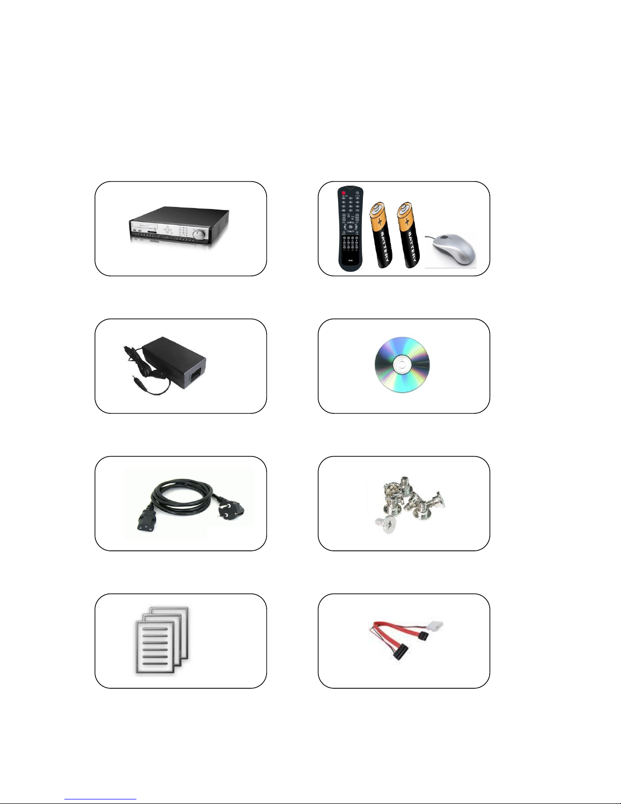
1.1 Packing Contents
The product box has the following contents, if any of these items are missing or damaged,
contact your dealer immediately before using the product.
DVR System Remote Control, Battery & USB Mouse
Power Adapter Software CD
Power Cable HDD Screws
User Manual HDD Cable
7
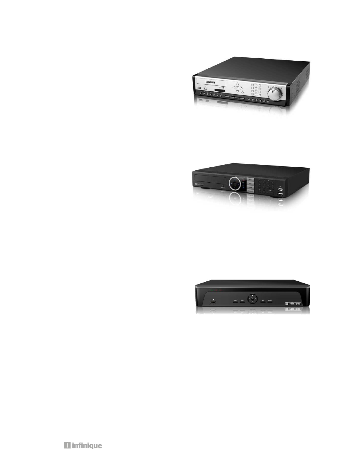
1.2 Product Models
Professional Series Model Numbers
IAR16-48W3I-SE1D: 16 Channel 960H DVR
IAR8-24W3I-SE1D: 8 Channel 960H DVR
960H Real-time Professional Series DVR with 3
SATA disk and DVD RW
System Series Model Numbers
IAR16-48W2I-SE1D – 16 Channel 960H DVR
IAR8-24W2I-SE1D – 8 Channel 960H DVR
IAR4-12W2I-SE1D – 4 Channel 960H DVR
960H Real-time Professional Series DVR with 2
SATA disk and DVD RW
Econo Series Model Numbers
IAR16-24W1I-SE1– 16 Channel 960H DVR
IAR8-24W1I-SE1 – 8 Channel 960H DVR
IAR4-12W1I-SE1 – 4 Channel 960H DVR
960H Real-time Professional Series DVR with 1
SATA disk and DVD RW
6 9 7 8 1 2 5 3 4
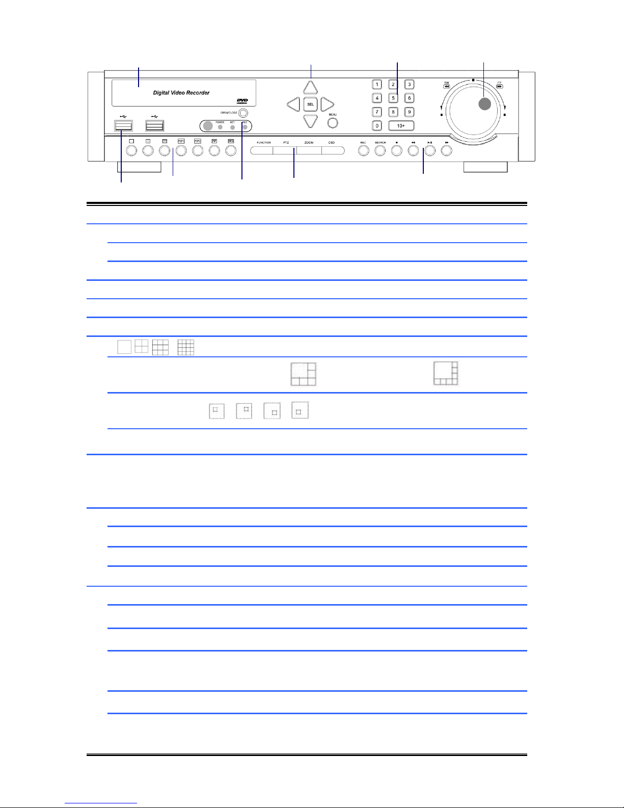
1.3 Front View - Professional Series DVR
1
DVD WRITER
DVD Writer Door
2
DIRECTION
Move the Curosor in MENU
SEL
Select Items
MENU
Go to System setup MENU
3
NUMERIC KEYS
Select Cameras or Input Numbers
4
JOG SHUTTLE
Control playback speed
5
USB PORT
USB Devices(Mouse,Memory Stick,HDD)can be connected
6
Screen Division Mode(1,4,9,16)
POP
POP1: 6CH Mode / POP2: 8CH Mux Mode
PIP
SEQ
(CAM01CAM02CAM03…..CAM16CAM1…..)
7
IR SENSOR/LED
POWER LED : POWER ON -> LED ON
NET LED : Network connected to DVR -> LED ON
REC LED : Recording -> LED ON
8
FUNCTION
Start Menu functions
PTZ
Go to PTZ control mode
ZOOM
ZOOM IN/OUT
OSD
Display/ hide OSD
9
REC
Start/Stop recording
SEARCH
Search recording file during playback mode
■
Stop playback
◀◀
Reverse playback, Step1/2/3,
Playback the previous frame in pause mode
▶I
Play and pause
▶▶
Fast forward playback step1/2/3
Playback the next frame in pause mode
9
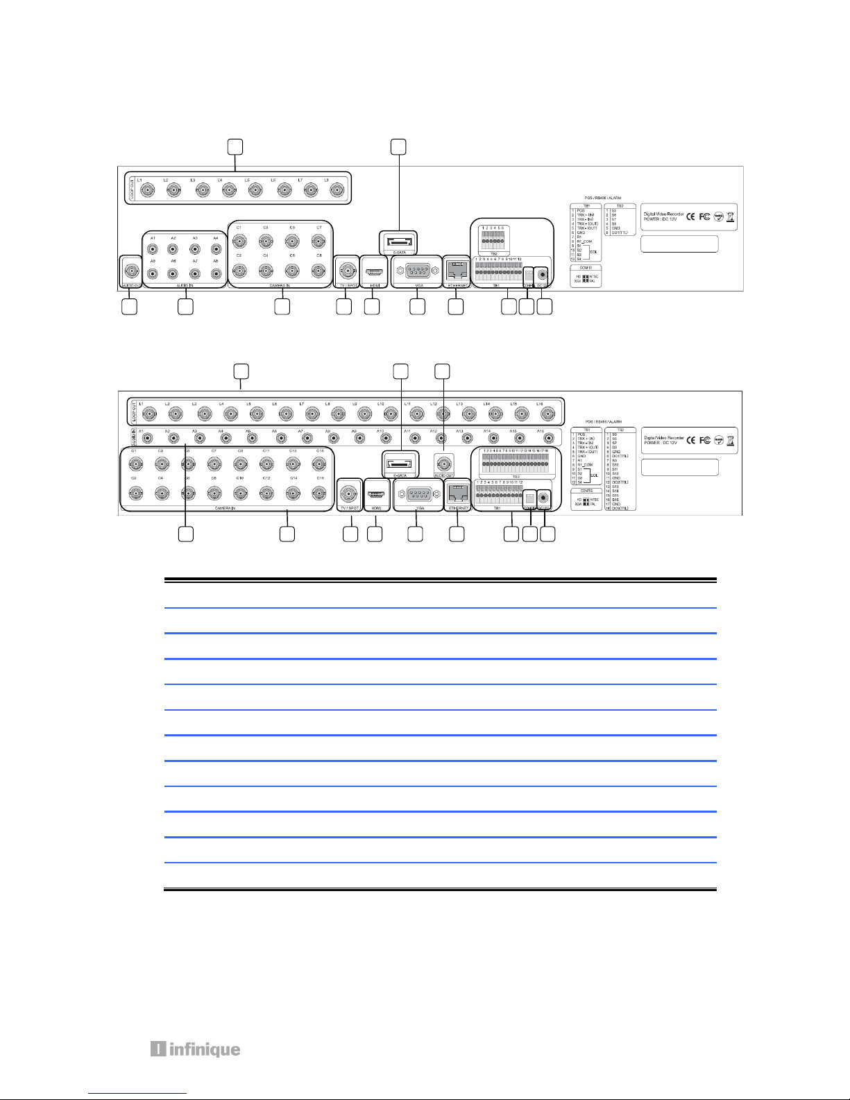
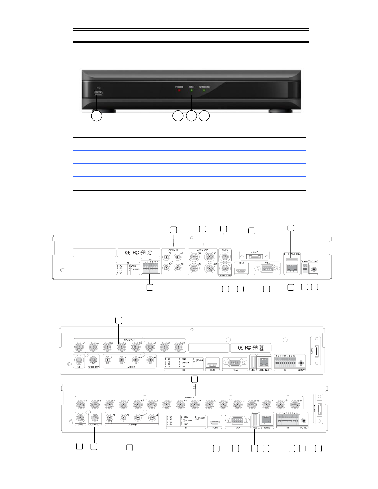
1.4 Rear View - Professional Series DVR
8 Channel DVR
16 Channel DVR
1
LOOP OUT
Video Signal loop-back output connection (BNC)
2
E-SATA
External SATA
3
AUDIO OUT
Audio output (RCA)
4
AUDIO IN
Audio Input Connection (RCA)
5
CAMERA IN
Video Camera Connection (BNC)
6
SPOT /TV
Live or SPOT out (BNC)
7
HDMI
HDMI output (HDMI type-C)
8
VGA
VGA or LCD mitor (D-SUB 15p)
9
ETHERNET
Cable Modem, Ethernet 10/100 Base-T (RJ-45)
10
TERMINAL BLOCK
RS-485 / Sensor In / Relay out / POS 1
11
CONFIG
NTSC/PAL HD/XGA (DIP S/W, 2-pin)
12
DC 12V POWER
5.83A Adaptor
1 2 10 3 4 5 6 7 8 9 11
12
1 2 3 4 5 6 7 8 9
10
11
12
6 7 1 2 5 3 4
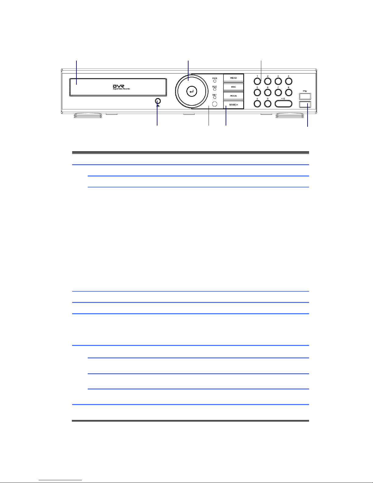
1.5 Front View - System Series DVR
1
DVD WRITER
DVD Writer Door
2
DIRECTION
Move the Curosor in MENU
SEL
Select Items
■
◀◀
▶I
▶▶
For Playback
Stop playback
Fast backward playback
Step backward(Playback the previous frame in pause
mode)
Play and pause
Fast forward playback
Step forward(Playback the next frame in pause mode)
3
NUMERIC KEYS
Select Cameras or Input Numbers
4
DVD EJECT
DVD Door Eject
5
IR SENSOR/LED
POWER LED : POWER ON -> LED ON
NET LED : Network connected to DVR -> LED ON
REC LED : Recording -> LED ON
6
MENU
Go to System setup MENU
REC
Start/Stop recording
MODE
Screen Division Mode
SEARCH
Search recording file during playback mode
7
USB PORT
To connect USB device (Mouse, Memory Stick, HDD)
11
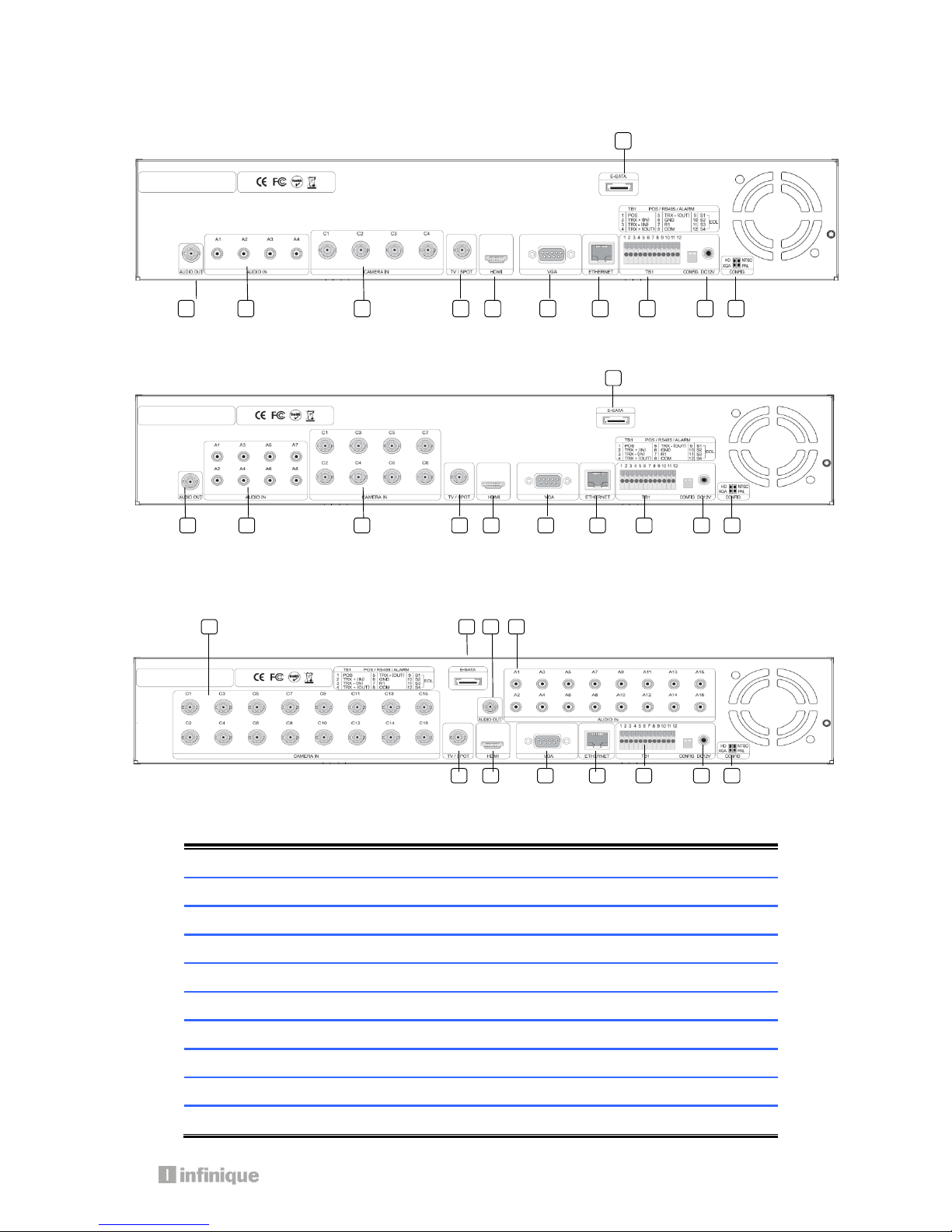
1.6 Rear View - System Series DVR
4 Channel DVR
8 Channel DVR
16 Channel DVR
1
E-SATA
External SATA
2
AUDIO OUT
Audio output (RCA)
3
AUDIO IN
Audio Input Connection (RCA)
4
CAMERA IN
Video Camera Connection (BNC)
5
SPOT /TV
Live or SPOT out (BNC)
6
HDMI
HDMI output (HDMI type-C)
7
VGA
VGA or LCD mitor (D-SUB 15p)
8
ETHERNET
Cable Modem, Ethernet 10/100 Base-T (RJ-45)
9
TERMINAL BLOCK
RS-485 / Sensor In / Relay out / POS 1
10
CONFIG
NTSC/PAL HD/XGA (DIP S/W, 2-pin)
1
2 3 4
5 6 7 8 9
10
11
5
6
7
8
9
10
11 1 2 3 4
5 6 7 8 9
10
11 2 3
4
1
11
DC 12V POWER
5.83A Adaptor
1.7 Front View - Econo Series DVR
1.
USB PORT
USB Devices(Mouse, Memory Stick) can be connected
2.
POWER LED
The Light turned on when Power is on
3.
REC LED
The Light turned on while DVR records something
4.
NETWORK LED
The Light turned on during network connection
1.8 Rear View - Econo Series DVR
4 Channel DVR
8 Channel DVR / 16Channel DVR
4
1 2 3
1
2 3 4
5
6
7 8 11
12
13
4
5
6
7
8 9 10
13 2 3 4 1
12
13
1
E-SATA
External SATA
2
AUDIO OUT
Audio output (RCA)
3
AUDIO IN
Audio Input Connection (RCA)
4
CAMERA IN
Video Camera Connection (BNC)
5
SPOT /TV
Live or SPOT out (BNC)
6
HDMI
HDMI output (HDMI type-C)
7
VGA
VGA or LCD mitor (D-SUB 15p)
8
ETHERNET
Cable Modem, Ethernet 10/100 Base-T (RJ-45)
9
TERMINAL
BLOCK(4CHANNEL)
Sensor In (1~4:+, 5:GND) / Relay out (6:+ / 7:GND)
10
RS-485(4CHANNEL)
For connection of RS-485 communication
11
TERMINAL BOLCK
(8CHANNEL
/16CHANNEL)
Sensor In (1~4:+, 5:GND) / Relay out (6,7:+ / 8:GND) /
RS-485 (9:+/10:GND)
12
USB PORT
USB Devices(Mouse, Memory Stick) can be connected
13
DC 12V POWER
3A Adaptor
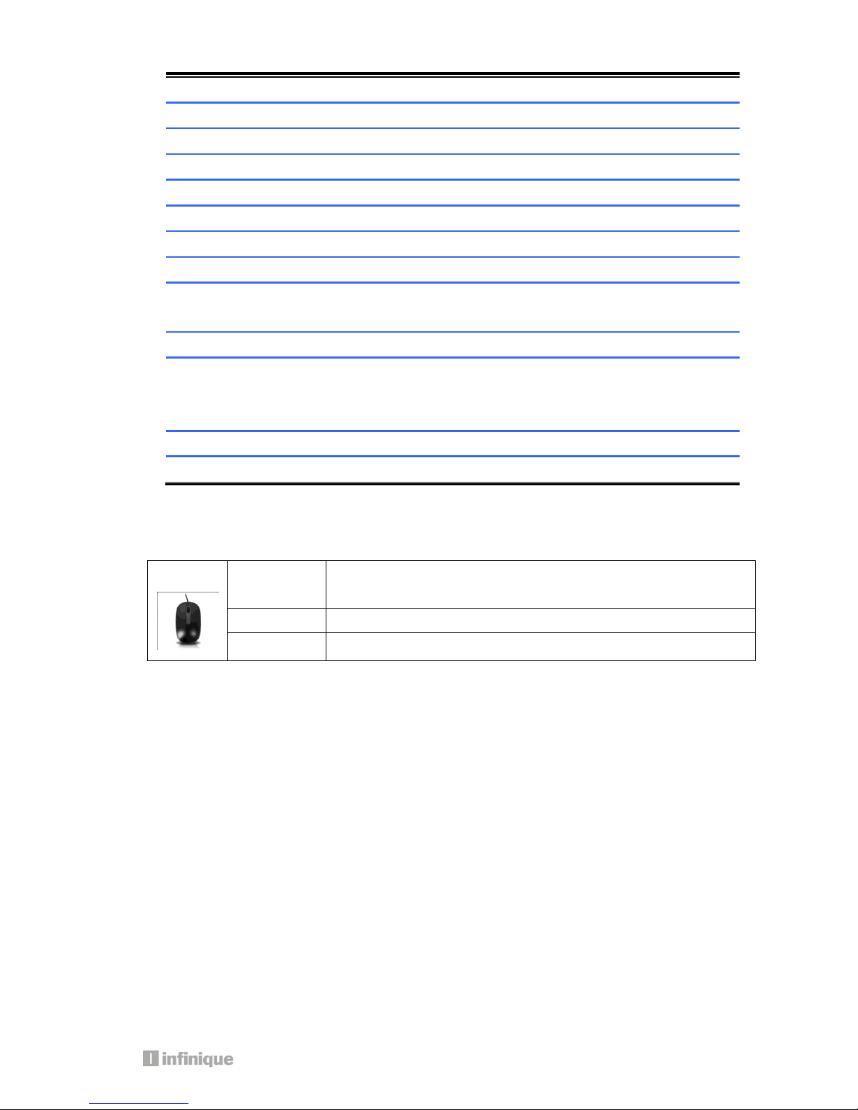
1.9 Mouse
A mouse is connected to the front or rear USB ports.
Left Click
Popup Login window/Selecting Icons/Its values
Selecting sub-menu in setup menu and values in each menu
Right Click
Popup Main Menu/Back from menu to live mode
Double click
Change one ch to multi ch or multi ch to one ch mode.
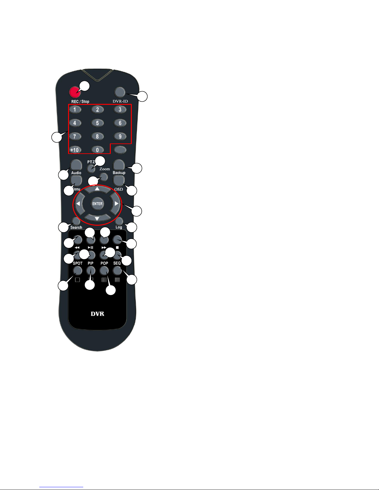
1.10 Remote Control
1) REC: Record button
2) DVR-ID: Used when controlling more than one DVR
3) Number Buttons
4) AUDIO: Audio ON / Mute
5) BACKUP: Back up recorded data to other device
6) MENU: Activate MENU mode for setup
7) OSD: Show or Hide OSD
8) PTZ: Control Pan/Tilt/Zoom camera.
9) Digital Zoom
10) Navigation Keys (▲,▼,◀,▶)
Move cursor or control PTZ camera
ENTER
Select sub item in system setup mode
11) SEARCH: Search recorded video
12) LOG: Show running status of DVR system
13) ◀◀: Reverse Play
14) ▶I: Play or Pause during playback
15) ▶▶: Fast Forward Play
16) ■: Stop Playback and go to Live mode
17) SPOT: Not Operated in this model
18) PIP: Go to PIP mode
19) POP: Enlarge specific channel in Live mode
20) SEQ: Show each camera rotation
21) Full screen mode
22) Quad screen mode
23) 9 Division screen mode
Operated only for 8ch or 16 channels
24) 16 Division screen mode
Operated only for 16 channels
1 3 4 7 6 8 10
11
9
13
12
14
17
22
19
16
15 2 5
21
23
24
18
20
15
2. Installing DVR
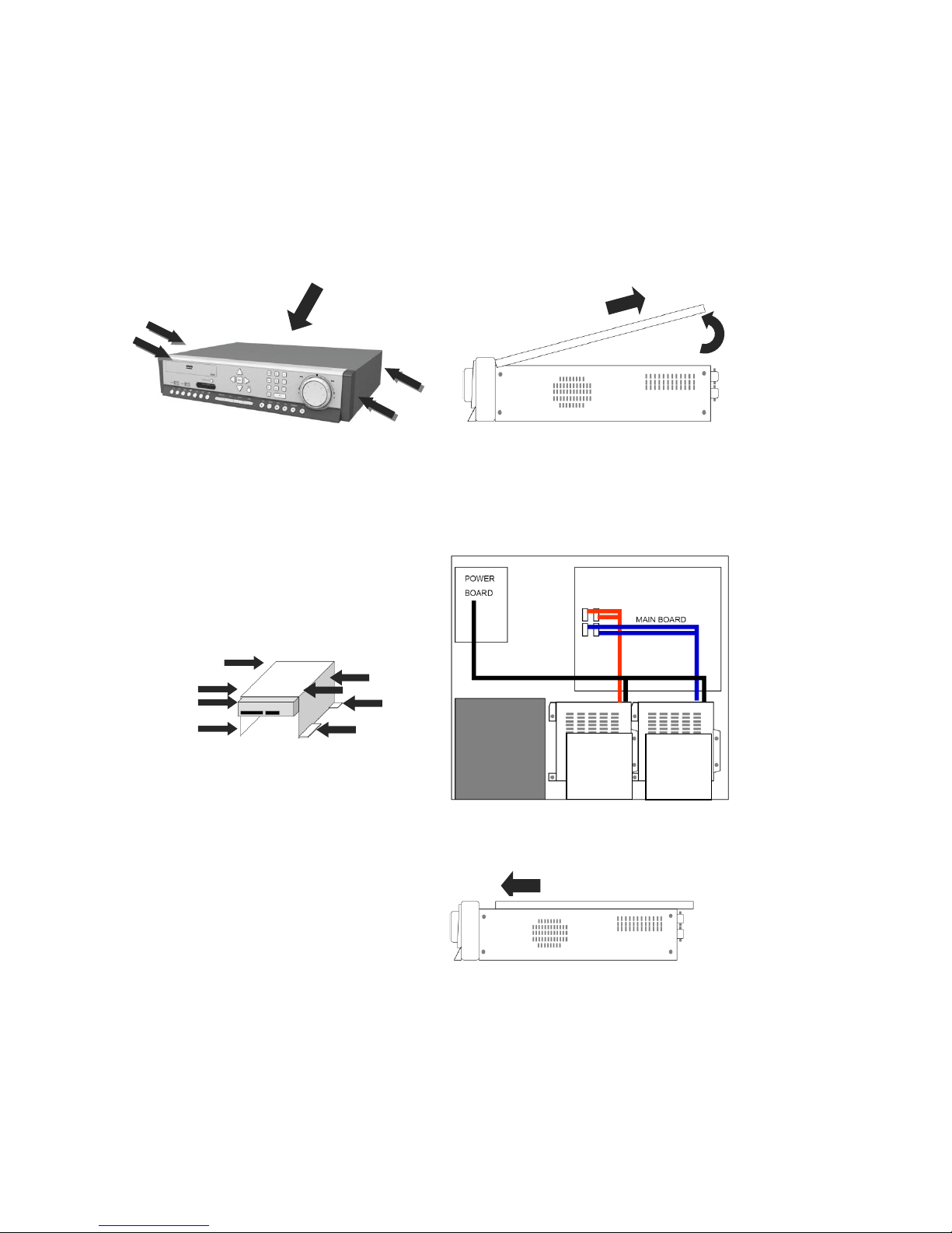
2.1 Installing HDD
One HDD should be installed inside the DVR to record the video.
If HDD is not installed in the product, please install HDD first as follows.
During installation, please take care from any sharp edges of the product
(1) Loosen screws on both sides and back
of DVR to detach the DVR cover
(2) Lift the end of top cover and pull it out
from DVR
(3) Loosen screws of HDD bracket to
detach from DVR. Put HDD in HDD bracket
and tighten with the supplied HDD screws
to bracket
(4) Restore HDD bracket to DVR and
connect HDD power cable and data
cable to HDD
(5) Insert top cover of DVR as per the
picture and tighten the screws again
2
1
HDD1
HDD2
HDD3
HDD4
17
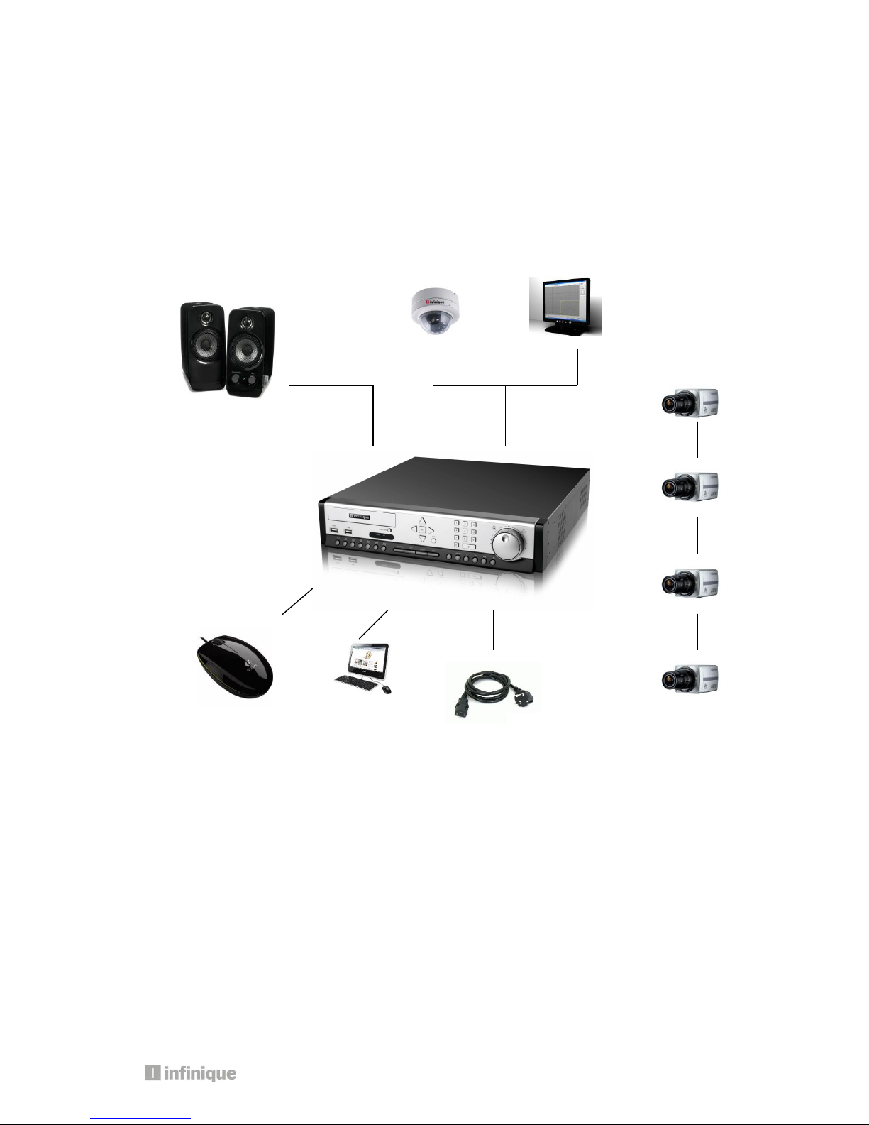
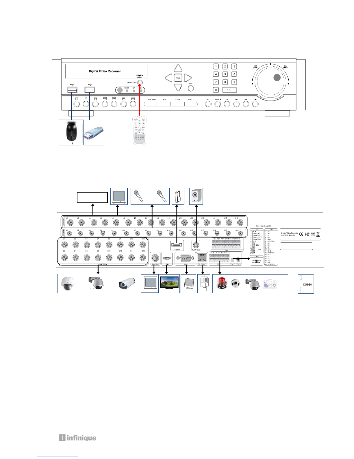
2.2 Connecting Devices to the DVR
2.2.1. Front
2.2.2. Rear
2.2.3. Connection of main devices
1) Adaptor
The adaptor supplied together with product is to be used. Third party adaptors can do
serious damages to the DVR.
2) Camera
Connect BNC video signal cable into [CAMERA IN] port on rear of the product. Please
connect the camera to the DVR when the DVR is off.
3) Audio, Sensor, Alarm, and RS-485
Sensor device should be connected to S and G port.
Alarm devices should be connected to A and G port.
The type of Alarm (NC/NO) has to be selected in DVR MENU in accordance with alarm
device.
PTZ camera or keyboard control is connected to RS-485(+,-) port. Please be careful not
. . . . . .
Loop out
. . . . . .. . . . .

to connect it to different polarity lest the device will fail to work.
4) Video Out
3 kinds of Video (HDMI, VGA, BNC) are supported by DVRs.
BNC is used for Live or Spot Monitoring.
When Video out is connected to VGA port of Monitor, the monitor resolution is either
1920 * 1080 or 1024 *768.
Please check CONFIG S/W in rear side for HD(1920*1080) or XGA(1024*768)
5) E-SATA
Some brands of E-SATA HDD Racks are not supported.
Please check whether HDD Rack is supported or not before usage.
6) USB Port
USB Mouse, USB memory stick, USB HDD, or external ODD drive can be connected to USB
port.
Note: External USB ODD doesn’t support multisession format, please check the CD
capacity and backup data capacity first before you backup recorded data to CD.
7) Ethernet Port
It is used to connect DVR to PC or LAN
3. Operation
19
Important: Please install a hard drive before using the DVR
3.1. Turning on
There is no power switch for the DVR. So, please connect all devices to DVR before it is
turned on.
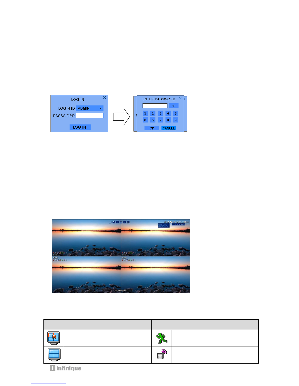
3.2 Log in
The log-in window will pop up after booting is over.
Please move the pointer into password window with mouse or up/down key of remote
controller, and then press enter button in remote control or right button of mouse.
Please enter default password (0000) in password window, and click OK icon and then
LOGIN icon.
It is ready to be accessable to DVR.
If you want to change password, please refer the [MENU-SETUP-SYSTEM-USER].
3.3 Screen Layout
You can see the below items according to your selection on function.
3.3.1 Icons in Live Mode
In Live display mode, icons will be indicated to notify the system mode or status.
Below are the icon categories, which are indicated on the monitor.
Icon for system
Icon for each channel
Selects specific 1ch with full screen
When Motion Detected
Screen-Division mode
When Sensor Activated

Check auto-backup with external
USB HDD (status, capacity)
Channel with audio connected
HDD capacity usage status
When PTZ mode entered
When USB memory stick & HDD is
inserted into DVR
When channel is recording
When DVR is connected via network
When panic record is activated
When DVR is not connected via
network
Icon in full screen mode
System ID for remote control
Channel sequence mode
Instant Playback (10sec, 30sec,
1min, 3min, 5min, 10min ago)
Digital x10 Zoom
Start/stop Panic(manual) record
3.3.2 Icons in playback mode
In search mode, the status will be shown in the upper side of screen. You can control
playback using the buttons.
ICON
Name
Description
Current status
This icon shows the current status in playback.
If you select ▶, the mark will be ▶,
Ex) If you select FF (fast-forward), ▶▶ will be shown.
Backward
Select backward and control speed (x2, x4, x8, x32 and x128)
In pause status, this button moves frame by frame reversely
Play
Play button. Select this button in pause mode

21
Pause
Pause button. Select this button in play, rewind or FF mode.
Fast Forward
Select fast-forward and control the speed (x2, x4, x8, x32 and x128)
In pause status, this button moves frame by frame forward.
Stop
Stop the playback and go to Live mode
Menu button also stop playing.
Search menu
Selecting this button, the Search sub-menu will pop up
Digital zoom
Digital zoom button in playback. Select this button to 1ch full
screen mode
Play speed
Indicates speed of rewind or fast-forward
Backup
Access to backup function
Bookmark
start
During playback, click this Icon and starting time is saved for
bookmark list
Bookmark
stop
Click this Icon and bookmark ending time is saved for bookmark list
Time Bar
Playback time
The color means whether the data is recorded or not in the time
Click the time by mouse, the data of the time is displayed

3.3.3 Other Icons
3.3.3.1 HDD Status
Indicates capacity of HDD and the percentage usage of HDD.
3.3.3.2 Screen Status
You can select different screen displays.
In Live MODE, there are 6 modes: PIP, POP, Sequence, Quad, 9 and 16.
Note: 9 and16 do not operate in a 4 channel DVR.
In play mode, there are 3 display modes: Quad, 9 and 16.
Note: 9 and 16 do not operate in a 4 channel DVR.
3.3.3.3 Channel Icon
Displays the video channel number being played or in live
There are 1~4 channels in a 4ch DVR and 1~16 channels in a 16ch DVR.
3.3.3.4 USB Icon
This Icon will be shown after you attach a USB device into DVR,
3.3.3.5 Network Icon
This Icon is shown while the DVR is accessed through network using remote viewing software.
3.3.3.6 Remote Control ID Icon
This Icon will be shown if system ID has been set in the system sub-menu.
The color of number displayed will be “Yellow” in case the status is active and if the number of
remote control matches the number of system ID. Otherwise, the color will be “RED”.
If you click Remote control ID Icon, you can see the following;
Status = Active [or De-active]
SYSEM-ID = 01, Request-ID = 01
Status denotes if the DVR can be operated or not with the remote control.
SYSTEM-ID denotes the number of remote control ID of DVR.
Request–ID denotes the number of Remote control you have got.
If you like to control the DVR with the remote control, the value of SYSTEM-ID should be the same
as that of Request-ID.
Note: You should press two digits when you select System-ID. Example, for number 5, press 0
and then 5. Do not press only 5. (Please refer to page 43 for setting remote control)
3.4 Other Remote Control Functions
3.4.1 Full screen mode
- Press button. By pressing button again, screen will show the next channel.
- Press desired numeric button on the remote control to go to specific channel
3.4.2 Quad screen mode
- To see quad screen mode, press button.
- By pressing button again, the next four channels are displayed in quad screen.
- If you press a numeric key of remote control which is inside current display range, selected
channel is displayed as full screen mode.

23
- If you press a numeric key of remote control which is outside of current display range, the
quad containing selected numeric will be displayed.
E.g. you press 6 while current screen shows CH1~Ch4, CH5~CH8 will be displayed.
3.4.3 Channel Display Mode for 8 or 16 Channel DVR
- To see cameras by 9ch mode, press button.
- If you press a numeric key of remote control which is inside current display range, selected
channel is displayed as full screen mode.
- If you press a numeric key of remote control which is outside of current display range, the nine
screens containing selected numeric will be displayed.
3.4.4 Channel Display Mode for 16 Channel DVR
- To see camera by 16ch mode, press button.
3.4.5 POP mode: Only for 8/16 Channel
- Press POP button to enlarge specific camera with 7 other cameras.
- By pressing POP button again, the biggest screen will change.
3.4.6 OSD Hide or Show
- Press OSD button of remote control if you want to see or hide OSD.
- You can set permanent hide status in SETUP menu [SETUP DISPLAY OSD]
When there is no command into DVR, status bar will be hidden. When you press
any button or click by mouse, Status bar will be shown again.
3.4.7 PIP mode (picture in picture)
In case of full screen display mode, you can see the other camera in a small window.
1 CAM01 2 CAM02
3 CAM03 4 CAM04
5 CAM05 6 CAM07
7 CAM07 8 CAM08
6
OSD button

(1) Press PIP button of remote control.
(2) If you press PIP button again in PIP mode, the position of cameras will interchange.
(3) Press numeric button of remote control in PIP mode to change small screen to
desired camera.
Example:
(4) Press Direction button or drag by mouse to move small screen to desired position.
3.4.8 Sequence Mode
- If you press SEQ button while in FULL or QUAD screen mode, screen(s) change in a
sequence automatically.
- Default value of changing interval is 2 or 3 seconds.
- User can select desired changing interval value from 1 to 99 seconds.
- User can select desired channels to display
3.4.9 Digital Zoom
If you press ZOOM key of remote control while in full screen mode, Digital-ZOOM
function is initiated.
If you press direction button of remote control, Zoom-Area window will move.
If you press ZOOM key again, Zoom-Area window will be enlarged or diminished.
If you press ENTER key, selected Zoom-Area will be displayed as full screen.
1
2
‘PIP’ Button
2
1
1
2
Cam ‘3’ Button
1
3

25
3.5. Mouse
System supports USB MOUSE
Just connect USB mouse to the port, the DVR will detect it automatically.
Note: Some types of USB mouse may not be compatible with DVR.
3.5.1 Change Screen Mode
Left mouse button is for selecting an item. Right button of mouse is usually for canceling
menu table or going to former menu mode.
If you double-click left button on a specific channel, the screen changes into full screen
mode. With double-click again; screen will go back to previous mode.
At PIP mode, if you want to change channel of small window, click right mouse button,
screen mode menu will appear. Click desired channel button.
3.5.2 Pop the Menu Window
Menu window pops up whenever you click the right mouse button.
3.6 Mobile Viewer
3.6.1 Mobile Viewing Method through web-browsing
Once your phone has access to internet, you can watch cameras through 3G Mobile phones.
The transmitted picture is in JPEG format, so no special application is required to operate. When
DVR is connected to Internet or LAN, it has its own IP address. You need this IP address to access
the DVR. Open internet browser, in the URL type:
http:// DVR IP address/mobile.html.
If you use a web-port other than the default 0080, you should add port number as below:
http://DVR IP address:port number/mobile.html.
Please see network section for more information.
Once you have entered the URL, you will see the following on your screen
Enter USER ID & PASSWORD, (default: netuser/0000) a Jpeg control box appears. Select channel,
size and delay. Then click start button.

Channel – Select channel you want.
Size – Select video resolution you want. There are two kinds: 352x240/176x120
Delay – The picture refreshed time, the unit is in seconds : real time, 0.5, 1, 2, 5
If you select 2, the frame is refreshed every 2 seconds.
3.6.2 Mobile viewing method through mobile-viewer application on smart phones
In this mobile viewing method use our custom mobile viewer software while using smart phones
such as iPhone or phones using Android OS. Using our custom software you can get much
better frame rate than the; JPEG viewer. You can download our mobile application supporting
iPhone and Android base.
<iPhone users>: mobile viewer is ‘aViewer’ search and download from app store.
<Android users>: mobile viewer is ‘DVRoid’, search and download from Google app.
For more detailed user manual of mobile viewer, please contact your provider.
NOTE
If recording resolution of DVR is set as 720*480, you cannot see video at 176*120
resolution in mobile phone. So, you should set up the recording resolution in DVR less
than 720*480 so that you can see the video at 176*120 resolution in mobile.

27
4. MENU
4.1 How to open MENU
Press MENU button on front keys or remote control, or click on the right button of mouse in
any position.
Before access to main menu, DVR asks you login ID and password.
When you first start DVR, input ADMIN for ID and 0000 for password as Initial ID & password
are ADMIN & 0000 respectively. Main menu consists of following icons: Setup, Search, Audio,
Spot, Backup, Log view, REC, OSD and Log out.
4.2. Set up
The followings are contents of sub-menu.
CAMERA
OSD
SEQ-FULL
SEQ-QUAD
GENERAL
PRIVATE ZONE
PTZ
PRESET
TOUR
COLOR
POS
DISPLAY
RECORD
EVENT
STORAGE
SYSTEM
PARAMETER
SCHEDULE
GENERAL
MOTION
SENSOR
VLOSS
E-MAIL
FTP
E-MAIL SCHEDULE
ALARM SCHEDULE
FTP SCHEDULE
MISC
HDD FORMAT
HDD SMART
AUTO BACKUP
NETWORK
SET UP
STREAM
DDNS
MOBILE
CONFIG
TIME
INPUT DEVICE
USER
UPGRADE
TURN OFF DVR

4.2.1. Display
Configuration related to OSD and Sequence patterns of main/spot monitors can be set.
4.2.1.1. OSD
OSD items that displays on monitor and language are selected.
Camera Name
Show camera name on screen.
Camera Number
Show each camera numbers on the screen
Camera Border
Show outline of channel
Language
Select OSD language
OSD HIDE
ALL, Time bar, Icon
AUTO HIDE Time out
ON: Hide ALL, time bar or icon automatically after selected time-
out.

29
4.2.1.2. SEQ-FULL
LIVE SEQUENCE: Set order of sequence channel and dwell time by second for main video out.
SPOT SEQUENCE: Set order of sequence channel and dwell time by second for spot out
CH
Input channel number.
TIME
Diplaying time on the channel from 0 to 99 : 0 means not to display the
channel
DEFAULT
The times are defaulted factory option. Default value is 2 second
All time
Same time is applied for all channels. Maximum time is 99 second
4.2.1.3. SEQ-QUAD

SEQUENCE : Set Quad- channel and dwell time by second for main video out.
CH
Sequence camera numbers. It can’t be changed.
TIME
Diplaying time on the channel from 0 to 99 : 0 means not to display the
channel
DEFAULT
The times are defaulted factory option. Default value is 3 second
4.2.2. Camera
General camera configurations such as camera name, Private zone can be made.
4.2.2.1. General
NAME
Input name of each camera using virtual keyboard.
Maximum 15 digits in English can be used.
COVERT
Show or hide camera image in live mode
ON: Hide camera, OFF: Show camera

31
AUDIO
Select connected audio channel
4.2.2.2. Private Zone
Note: The selected zone can not be seen in both live mode and recorded data
4.2.2.3. PTZ
This information can be found in manual of PTZ camera.
ID
Input ID of connected PTZ camera
PROTOCOL
Select protocol type of PTZ camera
BAUD
Select baud rate of PTZ camera
How to input letters or numbers on TEXT INPUT box
Move the pointer to the name box (Blank) and
click.
Click letters or numbers with direction button.
Click OK button after you complete input.
To protect privacy, User can choose the zone,
which is not seen for each camera.
Camera: select the channel that user want to
adjust private zone
Click on left button of mouse to select the
zone.
Separated zone can’t be selected
All users can’t see the selected private zone

4.2.2.4. Preset
CAMERA
Select PTZ camera to set up preset position : PTZ camera should be
connected.
PAGE
If more site is needed, please go to next page.
NAME
Preset position name can be written by virtual key board
SET
Move camera focus to the postion and save the position
CLE
Clear the preset
CLEAR ALL
Clear all of preset .please be careful when it is used.
Please follow the below steps to settle the preset.
1. Select PTZ camera to settle preset in camera.
2. Press “SET” ICON to pop up PTZ control window
3. Move camera to desired point by using Pan, tilt and Zoom in and out button.
4. Click Advance icon or Press ENTER Key in remote controller to save.
5. Click any other position on screen by mouse or press MENU Key to cancel.
If you like to cancel the setting, please click the CLE icon of the channel will be cleared.
If you click “CLEAR ALL” button, all value of channels will be cleared.
NOTE : Before using this function, please make sure that camera supports preset.
Total 64 preset points can be saved to each channel.
You can enter position name to each saved preset position.
4.2.2.5. TOUR

33
CAMERA
Select camera to set up scan point
LIST
Create another SCAN list reset
PRESET
Select desired preset potion
CLEAR ALL
Cancel all saved scan points
SEC
Dwelling time at the position
4.2.2.6. Color
The left pictue is the operation example.
1CH camera move like the followings.
PTZ01 (3 second staying )
>> PTZ02 (3 second staying)
>>PTZ03 (3 second staying ……
NOTE
In SCAN point menu, you can set up PTZ tour route(SCAN-LIST) using saved PRESET position.
You can create 4 scan lists for each camera. You should setup PTZ protocol and PRESET
before setting Scan-List.
Maximum 4 SCAN lists can be set and 1 SCAN list can be composed of up to 16 preset points

CAMERA
Select camera to set up scan point
BRIGHT
Bright of selected camera is adjusted
CONTRAST
Contrast of selected camera is adjusted
COLOR/SATURATION
Saturation of selected camera is adjusted
COLOR/HUE
Hue of selected camera is adjusted
4.2.2.7. POS
DVR support POS type terminal by USB serial. DVR support upto 4 POS interface.
4.2.2.7.1 POS SETUP
4.2.2.7.2 POS OSD
START CHARACTER
Start code of analyzed from POS equipment
END CHARACTER
End code of analyzed from POS equipment
LINE BREAK
Line deliminator (CR, LF, CR/LF) default is CR/LF
BAUDRATE
Communication Baud rate with POS equipment. Default is “1200”
DATABIT
Communinication Data Bit per characters. Default is “8”
STOP BIT
Communication Stop bit. Fixed as “1”
PARITY
Communication Parity bit. Fixed as “NONE”

35
NOTE
POS display support full screen live mode only on corresponding camera.
CH
Interworking Camera number with POS equipment.
DISPLAY LINE
Maximum displayed line numbers for POS data display.
Default is “20” (lines)
CLEAR TIME
Clear time when POS data display. Default is “10” (seconds)
ALIGN
String alignment method for POS data display. Default is “Left”
(align)
LIVE
Display POS data on live mode. Default is “OFF”

4.2.3. RECORD
Recording setup such as parameter, schedule and pre/post recording can be made in
RECORD menu
4.2.3.1. PARAMETER
Resolution
Recording resolution can be changed by “960H” “D1” “CIF”
EVENT
Select the recording picture quality and frame rate for EVENT occasions.
Event occasions mean when motion is detected or alarm is triggered.
Each channel can have separate picture quality and frame rate.
CONTINUOUS
Select the recording picture quality and frame rate for continuous
recording
Each channel can have separate picture quality and frame rate
The frame rate in CONTINOUS cannot exceed that of Event mode.
If frame rate of EVENT is set up as 8, and that of CONTINUOUS mode
cannot exceed 8.
ALL
Apply the same picture quality & frame rate for all channels.

37
4.2.3.2. SCHEDULE
DVR always records according to schedule.
Please make sure to set recording schedule during installation
NOTE: Recording schedule can be set by hour. The time in the first column of each line
means one hour.
4.2.3.3. GENERAL
OVERWRITE
When HDD gets full, the oldest record data will be erased and replaced
(overwritten) by new data. : ON is for [use OVERWRITE], OFF is for [not use
OVERWRITE]
If it is set OFF, DVR stops recording when HDD gets full.
REC OFF
No record, just monitor during selected hours.
CONTINUOUS REC
DVR records continuously during selected days and hours.
EVENT REC
DVR records only when Motion/Sensor/Video Loss is triggered
during selected hours.
CONTINUOUS+EVENT
REC
DVR records continuously or by events during selected days
and hours.
If no event, it will record video as continuous mode and
If event, it will record video as event mode as you set.

PRE-REC TIME
Recording time before events (0~30 sec)
POST-REC
TIME
Recording time after events (0~120 sec)
WATER-MARK
Generate water-mark in recording data Authenticity can be verified in
backup-viewer.
AUTO-DELETE
HDD only keeps the data of the the selected date. The value of zero(00)
means to diable auto-delete function. If 10 is selected, the data of 10
days from today is kept.
4.2.4. EVENT
4.2.4.1. MOTION
CAMERA
Select camera for motion setup
SENSITIVITY
Adjust motion sensitivity from 0~9
The higher number, the more sensitive detection
ALARM-OUT
Select alarm-out number which will be triggered when motion is detected.
RECORDCH
Select channels which will record when motion is detected.
BUZZER
Set ON/OFF for buzzer when motion is detected

39
NIGHT
MODE
Set separate sensitivity for day and for night. This option can be used in order
to avoid false motion event caused by camera noise at night.
SET ALL
All area (8x8 Grid) will be enabled for motion detection.
CLEAR ALL
All area (8x8 Grid) will be disabled for motion detection.
4.2.4.2. SENSOR
TYPE
Select NO(Normal open)/NC(Normal closed)
RECORD
Select camera channels which will record when sensor is activated.
ALARM-
OUT
Select alarm-out number which will be triggered when sensor is
activated.
BUZZER
Set ON/OFF for buzzer when sensor is activated.
4.2.4.3. VLOSS
ALARM-OUT
Select alarm-out numbers that will be triggered when video loss
occurs.
BUZZER
Set ON/OFF for buzzer when video loss occurs.
ALL
Apply the same settings to all channels.

4.2.4.4. E-MAIL
DVR can send e-mail notification when events occur.
NOTE: You can find SMTP server information usually from POP3/SMTP, IMAP/SMTP setup menu
of the server. Otherwise, you need to ask the server manager
EXAMPLE: If you have an account in Gmail, Input smtp.gmail.com in SERVER NAME and
ID/PASSWORD of your Gmail account. If normal is selected, you do not need to input in
SERVER NAME and ID/PASSWORD.
EXAMPLE: Email message
EVENT E-MAIL
Select ALL time or SCHEDULE for email notification
IMAGE
Check the box then DVR sends image as well as text when events
occur.
EVENT TYPE
Select event type from MOTION, POWER ON, SENSOR, HDD ERROR,
VLOSS
SENDER ID DVR
DVR sends email with this name.
E-MAIL ADDRESS
Input up to 2 email addresses receive email.
Example: anyone@gmail.com
SECURE TYPE
NORMAL: Standard email transfer, Port 21
SSL(485): Secure email transfer, Port 485
TLS(587): Secure email transfer, Port 587
SERVER NAME
In case of using SSL or TLS, input SMTP server name.
ID/PASSWORD
In case of using SSL or TLS, input ID and password of SMTP server.
From : DVR@dvr.com
To : anyone@gmail.com
Sent: Friday, July 24, 2011 6:11 PM
Subject: EVENT MESSAGE
[2011/07/24 18:10:11] [testdvr/192.168.001.121] MOTION ch 1 ON

41
4.2.4.5. FTP
DVR can send text + image to designated FTP server when events occur.
FTP
Select OFF,TEXT or TEXT + IMAGE
EVENT TYPE
Select event type to send to FTP.
FTP address
Input IP address or domain name of FTP server.
Account ID
Input ID to access FTP server
Account PW
Input password to access FTP server FTP
Directory Name
Directory of FTP server that will save transferred text or image
PORT
Input port number to use transfer to FTP
FTP normal uses port 21.
4.2.4.6. . E-MAIL/ALARM/FTP SCHEDULE
Make a schedule for e-mail transfer, alarm-out and ftp transfer for events.
Schedule can be arranged by day and by hour. Only during checked day and time, e-mail will
be sent and alarm out will be activated and ftp transfer will work
.
Select the date and hour by clicking the hour and
dragging mouse
Click all can activate all date and hours

4.2.4.7. MISC
DWELL TIME
Dwelling time for alarm-out
ALARM OUT
Alarm Type is selected as NC, NO
Alarm off is used to make Alarm sound off
EVENT POPUP
Channel where event occurs pops up in full screen mode.
POPUP OUT
NORMAL: Popup in main monitor
SPOT: Popup in spot monitor
POPUP SEQ TIME
Popup dwelling time
Note: If the event occurs during dwell time of another event, dwell time will be ignored and
newer event will pop up.
4.2.5. STORAGE
Up to 4 internal hard drives can be installed in the unit. Additionally 1 E-SATA hard drive can be
attached to the unit using E-SATA port in the rear.
4.2.5.1. HDD FORMAT
HDD must be formatted when installed in order to record properly.
Select HDD to format and click FORMAT button. When format is completed, DVR will reboot
automatically.
Time to format can be different depending on size of HDD but it usually takes a few minutes to
complete.
E-SATA information is always indicated after internal hard drive(s).

43
4.2.5.2. HDD SMART
Temperature of HDD can be checked. If the temperature gets higher than certain point, DVR
can notify user of that. Select ON in SMART to use this funciton
THRESHOLD
Set the limit temperature of HDD.
INSPECTION CYCLE
Set the interval to check HDD temperature. Every 10 minutes, Hourly and
Daily
DAILY TIME
In case you select “Daily” in inspection cycle, set time to check HDD
temperature during a day.
ALARM OUT
Select ports which will activate when HDD temperature exceeds over set
threshold.
BUZZER
Select ON/OFF of buzzer sound when HDD temperature exceeds over set
threshold.

4.2.5.3. AUTO-BACKUP
Once USB HDD is connected to DVR, HDD status is indicated.
Recording file list can be checked by selecting SHOW.
EXTEND
When internal HDD(s)(including E-SATA HDD) gets full, HDD starts to overwrite
and eldest data will be erased from internal HDD and saved in USB HDD at the
same time. This works when overwrite is set to “ON” in [MENU-SETUP-
RECORD_MISC]
MIRROR
Same data of internal HDD will be recorded in USB HDD.
INTERNAL
To use this function, more 2 internal HDD must be installed. Same data is
recorded to paired internal HDDs : HDD1 and HDD2, HDD3 and HDD4 works
as pairs.
Example) supposed HDD1, HDD2, HDD3 are installed and set as INTERNAL
function,
HDD1 and HDD2 record same data as RAID 1, but since there is no pair to
HDD3,
Data recorded to HDD3 is not mirrored to HDD2. HDD2 is not pair of HDD3.
4.2.6. NETWORK

45
4.2.6.1. Setup
TYPE
Select network type among STATIC, DHCP and ADSL(PPPOE)
DHCP: DVR automatically gets IP address, gateway and subnet mask.
STATIC: Check your network environment and input IP address, gateway
and subnet mask manually.
ADSL : Input PPPOE ID and PASSWORD.
IP ADDRESS,
GATEWAY,
NETMASK
Activated only when TYPE is set to [STATIC]
PPOE ID,
PASSWORD
Activated only when TYPE is set to [ADSL]
MOBILE PORT
Default is 7620, and used transfer Jpeg stream to mobile viewer.

CLIENT PORT
Default is 7621, and used to transfer video stream to Netclient.
WEB-PORT
Default is 0080, and used to transfer video stream to web viewer.
BANDWIDTH
Selected as 64, 128, 256, 512 Kbps, 1,2,4,10Mbps, and unlimited speed.
AUTO PORT
FORWARDING
Check port forwarding for network connection from outer network.
Automatically Router allocates IP to DVRs and does port forwarding.
To use this function, Router should support uPnP function.
PORT
FORWARDING
STATUS
Port Frowarding OFF, ON is displayed according to status of uPnP.
When it is changed to ON, the port is allocated succeed.
STREAMING
H.264 : recording resolution is transferred in Webviewer, netclient.
JPEG : still image is transferred in Webviewer,netclient, and Mobile viewer.
Mobile application can always receive only JPEG image
Note: All the ports numbers can be input from 0001~9999 without duplication.
4.2.6.2. DDNS
DVR supports DDNSCCTV.COM, DDNSCCTV(AUTO), DYNDNS.COM and NO-IP.COM for DDNS
connection.
Using DDNSCCTV.COM(AUTO)
If you choose DDNSCCTV.COM(AUTO) in SERVER, DVR creates HOST NAME using DVR
using MAC address of DVR.
1. Click DDNSCCTV.COM(AUTO) in SERVER.
2. Then USER ID, PASSWORD and HOST NAME are generated automatically using MAC
address.
3. USER ID, PASSWORD and HOST NAME are formed in DVR + last 6 letters of MAC
address.
Example: If MAC address of DVR is 00:0E:B5:02:8A:5F, USER ID & PASSWORD are
dvr028a5f and HOSTNAME is dvr028a5f.ddnscctv.com
Using DDNCCTV.COM, DYNDNS.COM or NO-IP.COM
SERVER
Select DDNS server

47
USER ID
Input DDNS server account ID
PASSWORD
Input DDNS server account password
HOST NAME
Input domain(host) name that you made at DDNS server
CONNECT
Click the button to check connection to DDNS server. If
connection is ok, STATUS shows DDNS OK
NOTE: To use DDNS function, you must first visit www.ddnscctv.com, www.dyndns.com
site or www.no-ip.com on PC and create an account and make a domain (host) name.
NOTE: If DDNS connection fails, check if all information has been input correctly
(especially USER ID and PASSWORD) and check network status.
How to register DDNSCCTV
Input http://ddnscctv.com on web browser of
PC to use DDNS service before you make
configuration on DVR
Click Registration button if you do not have an
account.
Fill in E-mail address, password, name etc.
Then, click Submit button
Input domain name you wish to create and click
Request Domain button.
Domain name can be created with combinations
of alphabets, numbers and marks.
(You must not put a mark on first letter of domain
name.)
Click Logout button after domain name has been
successfully registered.
You can sign in with E-mail and password you
registered.

DDNS setup on DVR
1. Move to SETUP NETWORK DDNS
2. Select DDNSCCTV.COM (3 options : DDNSCCTV.COM, NO-IP.COM, DYNDNS.COM)
3. Input E-mail address & password you registered at http://ddnscctv.com on USER ID and
PASSWORD.
4. Input domain name you registered at http://ddnscctv.com on HOSTNAME.
How to use DDNS
Input domain name you registered on web browser. => Example: http://abc.ddnscctv.com
For WAN connection, DVR web port/client port should be forwarded. (Port-forwarding)
Example: If webport is set 1000 on DVR, http://abc.ddnscctv.com:1000
4.2.6.3. JPEG

49
When connecting to DVR remotely from webviewer or Netclient, Resolution & frame rate of
JPEG stream can be set up. Resolution options are D1(720*480) and CIF(320*240), and
maximum frame per channel is 30fps.
4.2.7. SYSTEM
Configurations for time, user and etc. can be made.
Software version can be checked and upgrade process can be made
4.2.7.1. CONFIG
System setting values from one DVR can be copied to others.
Insert USB device into USB port of DVR to import (load) or export (save) the setting values.
CONFIG IMPORT & CONFIG EXPORT can be used to make several DVRs to have the same
setting values.

CONFIG IMPORT
Load the saved configuration file from USB device.
CONFIG EXPORT
Save the configuration file to USB device to copy it to another DVR
DEFAULT
Change all configuration values back to factory default.
4.2.7.2. TIME
DATE
FORMAT
Select date format : YY/MM/DD,MM/DD/YY
TIME
FORMAT
24HOURS or AM/PM
TIME ZONE
Select time zone of your location
TIME SYNC
System time will be synchronized with selected time server if it is turned ON.
SERVER IP
Input IP or domain name of time server.
Click TEST if connection with server is OK.
DVR checks time server for correct time every 1 hour.
Ex) time.windows.com ( http:// is no needed)
CHANGE
TIME
Change time manually
4.2.7.3. INPUT DEVICE

51
How to set up System-ID status
System-ID status shows whether the system will accept key from remote-control or not.
SYSTEM-ID is used when user operates several systems with one remote control.
SYSTEM- ID will be displayed when SYSTEM- ID is other than 0(zero).
By using DVR-ID button of remote control, remote control can be matched to SYSTEM- ID, or if
SYSTEM- ID is 00, system-ID is not displayed and system accept key from remote control.
If SYSTEM- ID color is white, the system accepts remote-control key input.
If SYSTEM- ID color is red, the system does not accept remote-control key input.(No beep)
How to match SYSTEM- ID by remote control
(1) Press DVR-ID button of remote control.(You can hear short double-beep.)
(2) Then, press desired System-ID by using 2 numeric button. (E.g. 02 or 03 or 01)
Activated status : Inactivatived status :
4.2.7.4. USER
There are 2 fixed users, ADMIN & NETUSER. Their name & access authority cannot be changed.
Additionally, you can create up to 20 more users and give different access authority level to
each user.
SYSTEM-ID
Input the number that you want to register in this DVR.
KEYBOARD
DVR system can be connected with control keyboard.
KEY-TONE
Beep whenever button is pressed if ON is selected.
Active ID : 02
Working
Not working
Not working
R : 01
R : 02
R : 03

USER – There are two unchangeable user IDs (ADMIN, NETUSER), to create new user or
modify settings of existing users, click arrow button.
PASSWORD – Initial password for each user is set ‘0000’. When you create a new user,
make sure that you have to enter new password and do not forget the newly input
password. Up to 8 digits of numbers can be used for password (EX: 123456)
SETUP – Check this box then the user is authorized to go into setup menu
DVR FUNCTION– Click DVR function button of REC (Recording setup), PLAY (SEARCH),
BACKUP and PTZ (Control) to give each user access authority.
NETWORK – Check this box then the user is authorized to access to DVR via network (Web,
CMS or mobile)
COVERT CH – Select covert channels by each user. Marked channels will be hidden by
the user
START UP LOGIN – Log-in Windows pop up when it is set to “ON”, if it is changed to
“ OFF” , the intial Log-in Windows doesn’t pop up any more.
TIME OUT – When this is set to ON, LOGIN window will re-appear after entered time from
any signal input. If you want to log out, you need to go to MENU and select LOG OUT like
right picture.
MONITOR – First select ON to give monitoring authority to each user. Then click CH button
to select monitoring channel the user can access.
4.2.7.5. UPGRADE
You can check version information of software and firmware upgrade can be done.

53
USB UPGRADE
Please select USB upgrade in upgrade window
1. Copy provided firmware file to your USB memory stick
2. Insert USB Memory which includes Firmware into USB Port.
3. Enter UPGRADE button to upgrade firmware, then small windows will appear.
4. Please click OK Icon and the message dialogue to confirm will popup,
5. And please click OK, or CANCEL to proceed.
It will take some minutes to upgrade, and then DVR will be rebooted automatically after
upgrade is finished.
NETWORK UPGRADE
Please select network upgrade in upgrade window
1. Check out whether Server IP and FILE NAME are correct.
If shown information is wrong, correct SERVER IP and FILE NAME and press ENTER button
to input new information by text input Dialog box.
NOTE : Make sure the information of Server IP & File name through your supplier.
2. Select OK and press ENTER button to start S/W upgrade.
After completing upgrade, the system will reboot automatically.
4.2.7.6. TURN OFF DVR
Select TURN OFF DVR and software of DVR will be shutdown.
In order to completely shut down DVR, turn off the power switch in the rear.

4.3. SEARCH
Time search using calendar/time bar and event search using event logs and POS search are
supported.
4.3.1. SEARCH BY TIME
NOTE: Dates with recording data are shown in yellow, Hour/minute with recording data are in
bright blue.
4.3.2 SEARCH BY EVENT
Select date on calendar and then hour & minute on time
bar
Click “PREVIEW” button after selecting minute and
channel no.
Click “PLAY” while running preview and it enlarges into full
screen.
To watch playback without preview, just click “PLAY” after
selecting minute.
GOTO FIRST/ GOTO LAST: Playback of earliest/ latest
data.

55
4.3.2 THUMBNAIL SEARCH
Thumbnail search is effective and quick search option. You can search recorded file of certain
channel by displaying 9 screens at a time by selected time interval.
Seeing the capture image, double-click on certain screen then it will be divided in smaller
interval.
If you set 10:00AM in TIME and 1 hour in INTERVAL then first screen shows 10:00AM and second
11:00AM. Double-click on second channel and it will be divided again in 9 screens by 10
minute (1 minute, 10 seconds and 1 second) starting from 11:00AM.
4.3.4. SEARCH BY POS
CH
Select channel number to view
TIME
Select time to start “Thumbnail search”
INTERVAL
Select time interval from 1 sec, 10sec to 1 minute & 1 hour.
VIEW
Capture image by selected interval starting from selected time shows up
If 1 hour is selected, each screen shows by 1 hour of the same channel.
NEXT,
PREVIOUS
Previous or next page of recorded file by selected interval.
Select DATE & TIME to get event logs
Select CH to get event logs
Select EVENT TYPE to get event logs
Select SEARCH button and event log list will be written.
<PGUP, >PGDN: Page up & down of list
<<FIRST, >>LAST: Go to first page or last page of list
Click an event log on list then DVR goes to the time when the event happens in search mode.

START TIME
POS search start time
END TIME
POS search end time (Auto ajusted according to start time within 24 hours)
KEYWORD
Search Keyword ( If select “OFF”, search all. Whereas select “ON”, search
keyword.)
CAMERA
Serach Camera number.
Record item show “O” or “X”(“O” means recorded).
When you select “O”, you can play at POS start time.
4.3.5. BACKUP
Recorded data can be archived in USB device or CD/DVD using backup function
First, insert USB device or CD/DVD and select backup menu from main menu or press backup
button on remote control and below popup will show up.

57
DEVICE
Select device for backup
MEDIA TYPE
Select connected device to backup
CHANNEL
Select channel(s) to backup
To AVI
Data will be archived in AVI format
If unchecked “To AVI”, data will be archived in PS format and backup viewer
program will be automatically copied.
TIME STAMP
Insert time stamp into AVI file
FROM/TO
Select starting time/End time to back up.
Without inputing time directly, 1 minute ~ 60 minutes of backup can easily
be made.
BOOKMARK
Go to bookmark list that have been made in playback mode
4.3.6. PLAYBACK MODE
When DVR is in search mode, you can play, pause, rewind & fast-forward (x2, x4, x8, x32 and
x128)
If you move mouse cursor at the bottom of screen, time bar pops up and you can drag and
move the time in the bar. Time bar contains 24 hours and time of recording data is indicated in
brighter blue. By bookmark icon you can select starting and ending time of backup file here.

4.4 Other functions
4.4.1 PTZ
If you press button of remote control or select PTZ in main menu, screen will be changed
to FULL screen mode and you can control PTZ camera.
If you press advance button in PTZ window, PTZ- ADVANCE window will pop-up.
4.4.1.1 PTZ BASIC
Press ◀▶▲▼ button and camera will pan to left / right or tilt up / down.
Press ◀◀ / ▶▶ button or search / log button of remote control or click (+), (-) button and
camera will zoom in or out.
Press numeric button of remote control and target camera will be changed.
4.4.1.2 PTZ ADVANCE
FOCUS
+ : FOCUS-IN.
- : FOUCS-OUT
AUTO : AUTO FOCUS MODE.
IRIS
+ : OPEN IRIS.
- : CLSO IRIS.
AUTO : AUTO-IRIS MODE
SPEED
+ : The control speed will increase.
- : The control speed will decrease.
PRESET
If you want to go to a specific PRESET-position, select “GO” button.
If you want to go to a SCAN-positions, select “SCAN” button

59
NOTE:
The PRESET-positions are set by PRESET menu [MENU SETUP CAMERA PRESET]
The SCAN-lists are set by SCAN-POINT menu [MENU SETUP CAMERA SCAN-POINT]
OSD MENU
If you click OSD MENU icon in case that Camera itself has OSD function, The OSD will be
shown in accordance with Camera’s OSD. If OSD is not supported by Camera, OSD MENU does
not work.
4.4.2 Audio
4.4.3. SPOT
COMPOSITE
The video is displayed as Composite
SINGLE CHANNEL
Selected one CH screen is displayed
SINGLE SEQUENCE
One CH is sequenced
QUAD
4CH screen is displayed.
The Quad channel can be selected.
QUAD SEQUENCE
Quad screen is sequenced
MODE 9
9 CH screen is displayed
MODE 16
16CH screen is displayed. (just in 16CH)
4.4.4 LOG VIEW
System log status can be found or saved into USB memory to check on PC.
Before using this function, make sure audio in/out
device has been installed correctly. (Refer to page
Audio out works only in 1CH full screen mode
Test audio by TEST ON/OFF button

EVENT TYPE
Select event type to see logs.
FROM
Input staring time.
TO
Input ending time.
BACKUP
Save log data into USB memory.
SEARCH
Click SEARCH button and log list will be shown.
EVENT LIST
Logs of checked EVENT TYPE will be listed.
4.4.5 OSD OFF
Select OSD OFF then OSD (icons or time) will disappear/appear.
Please see the page 21 to get more information. [SETUP->DISPLAY->OSD]
4.4.6 REC
Select REC button on main menu, on remote control or on front panel. Then, all channels will
record regardless of previous recording schedule setup. This function can be used when
unexpected incident occurs in channels that are not recording by operator, it is said to be
panic or instant recording. Pressing One more REC button makes DVR go back to the previous
recording schedule setup. During Panic recoding, Icon is displayed in each channel.
Example: While only channel 2,3 and 4 are recording by the current recording schedule,
unexpected incident is happening on channel 1, so channel 1 needs to be recorded.
In this case, select REC function instantly on remote control or on front key. Then all channels will
be recorded as panic recording status.
4.4.7 LOG OUT
Select LOG OUT button and DVR will go in logged out status.

61
You cannot control DVR and change settings of DVR in logged out status. In order to log in
again, press any button of remote control or front key or click mouse button on any spot
of screen.
NOTE: When DVR goes in logged out status, all channel might be blocked by covert
according to settings in [System -> USER-> Monitor -> ON]

5.Trouble shooting
In the event of a product malfunction, please check the following list for a usual and possible
solution before requesting service.
1. Product is not turned on.
Check out whether the power is being supplied well.
2. Product continues displaying “Loading” or “Starting UI….”
Check the product can boot without HDD
If product continues displaying “Loading” or “Starting UI….” Without HDD, you can try emergent
upgrade. Please refer method of factory default in provided CD
3. Camera video is not displayed on monitor
Check the video input / output connections on the product rear panel.
Check the camera status and the connection between camera video/power cable.
Check if CAMERA STATUS in menu is SHOW.
4. I cannot hear Audio
Check the audio input/output connections on the rear panel of DVR.
Audio works only in full screen mode.
5. I can’t stop recording by remote controller or REC button
Check out that RECORD CONTINUOUS of REC OPTION of MENU is OFF.
6. I can’t find previous recording data.
The product operates automatically OVERWRITE function. It deletes the oldest recording data to
overwrite when HDD is full.
7. Product is not compatible with external USB device.
Please check if USB memory stick is in protection (password) function. Protection function of USB
device should not be discharged.
8. I can’t connect to network.
Check if network of menu is setting correctly such as Network port, ID, Password
Check if your internet line is available. Please ask your service provider to check internet line.
If the problem you are experiencing persists or is not mentioned above, please contact service
center or your local distributor.

63
Infinique Digital Security Systems
© 2011 Infinique. All rights reserved. This product or document is protected by copyright and distributed
under licenses restricting its use, copying, distribution and recompilation. No part of this product or
document may be reproduced in any form by any means without prior written authorization of Infinique.
Worldwide Inc and its licensors, if any.
Infinique Worldwide Inc
151 Brunel Road
Mississauga, Ontario
Canada, L4Z 2H6
Infinique EMEA FZC
PO Box 122117
R4-24, Sharjah Airport Free Zone
Sharjah, United Arab Emirates
DISTRIBUTED BY
Design and specification are subject to change without notice.
 Loading...