

Infinique IAR16-48W3I-SE1D, IAR8-24W3I-SE1D, IAR16-48W2I-SE1D, IAR8-24W2I-SE1D, IAR4-12W2I-SE1D Operating Instruction
...
960H Digital Video Recorders
Operating Instructions
Professional Series Model Numbers
IAR16-48W3I-SE1D, IAR8-24W3I-SE1D
System Series Model Numbers
IAR16-48W2I-SE1D, IAR8-24W2I-SE1D, IAR4-12W2I-SE1D
Econo Series Model Numbers
IAR16-24W1I-SE1, IAR8-24W1I-SE1, IAR4-12W1I-SE1
Before attempting to connect or operate this product,
please read these instructions carefully and save this manual for future use.
RoHS
Important Safety Instructions
Read and keep these instructions
Heed all warnings
Follow all the instructions
Do not use this apparatus near water and clean only with a dry cloth
Do not install near any heat sources such as radiators, heat registers, or other apparatus
that produce heat
Protect the power cord from being walked on or pinched particularly at plugs,
convenience receptacles, and the point where they exit from the apparatus.
Unplug this apparatus. When a cart is used, use caution when moving the
cart/apparatus combination to avoid injury from tip-over.
TO REDUCE THE RISK OF ELECTRIC SHOCK, DO NOT REMOVE.
NO USER-SERVICEABLE PARTS INSIDE. REFER SERVICING TO QUALIFIED SERVICE PERSONNEL ONLY.
.
FCC For Class-A Digital Device
A CLASS-A digital device complies with Parts 15 of the FCC Rules.
Operation is subject to the following two conditions.
This device may not cause harmful interference.
This device must accept any interference received, including interference that may cause
undesired operations.
The lightning flash with an arrowhead symbol within an equilateral triangle is
intended to alert the user to the presence of un-insulated “dangerous
voltage” within the product’s enclosure that may be of sufficient magnitude
to constitute a risk of electric shock to persons.
The exclamation point within an equilateral triangle is intended to alert the
user to presence of important operating and maintenance (servicing)
instructions in the literature accompanying the appliance

3
Table of Contents
IMPORTANT SAFETY INSTRUCTIONS .............................................................................................. 2
FCC FOR CLASS-A DIGITAL DEVICE ............................................................................................. 2
1. PRODUCT OVERVIEW .............................................................................................................. 6
1.1 Packing Contents .............................................................................................................. 6
1.2 Product Models ................................................................................................................. 7
1.3 Front View - Professional Series DVR .................................................................................... 8
1.4 Rear View – Professional Series DVR ......................................... Error! Bookmark not defined.
1.5 Front View - System Series DVR ........................................................................................... 9
1.6 Rear View - System Series DVR.......................................................................................... 11
1.7 Front View - Econo Series DVR .......................................................................................... 11
1.8 Rear View - Econo Series DVR .......................................................................................... 12
1.9 Remote Control ............................................................................................................... 12
2. INSTALLING DVR ................................................................................................................... 15
2.1 Installing HDD .................................................................................................................. 16
2.2 Connecting Cameras and Audio Device ........................................................................ 17
2.2 Connecting a Monitor ............................................................ Error! Bookmark not defined.
2.4 Connecting to a Local Area Network ...................................... Error! Bookmark not defined.
2.5 Connecting Optional Devices ................................................ Error! Bookmark not defined.
2.6 Connecting Power Supply ....................................................... Error! Bookmark not defined.
3. OPERATION .......................................................................................................................... 18
3.1 Switching on ........................................................................... Error! Bookmark not defined.
3.2 Initial Screen ........................................................................... Error! Bookmark not defined.
3.2 Screen Layout ........................................................................ Error! Bookmark not defined.
3.2.1 Icons in Live Display Mode ................................................ Error! Bookmark not defined.
3.3.2 Playback Buttons .............................................................. Error! Bookmark not defined.
3.3.3 Other Icons ............................................................................................................... 22
3.4 Other Remote Control Functions ...................................................................................... 22
3.4.1 Full screen mode ...................................................................................................... 22
3.4.2 Quad screen mode .................................................................................................. 22
3.4.3 Channel Display Mode for 8 or 16 Channel DVR ........................................................ 23
3.4.4 Channel Display Mode for 16 Channel DVR ............................................................... 23
3.4.5 POP mode: Only for 8/16 Channel ............................................................................. 23
3.4.6 OSD Hide or Show ..................................................................................................... 23
3.4.7 PIP mode (picture in picture) ...................................................................................... 23
3.4.8 Sequence Mode ....................................................................................................... 24
3.4.9 Digital Zoom.............................................................................................................. 24
3.5. Mouse ............................................................................................................................ 25
3.5.1 Change Screen Mode .............................................................................................. 25

3.5.2 Pop the windows to input the values .......................................................................... 25
3.6 Mobile Viewer .................................................................................................................. 25
3.6.1 Mobile Viewing Method through web-browsing .......................................................... 25
3.6.2 Mobile viewing method through mobile-viewer application on smart phones ............ 26
4. MENU ................................................................................................................................... 27
4.1 How To Display Menu Window ................................................. Error! Bookmark not defined.
4.1.1 Setup ............................................................................... Error! Bookmark not defined.
4.2 Setup Menu ........................................................................... Error! Bookmark not defined.
4.2.1 Display ............................................................................. Error! Bookmark not defined.
4.2. 2 Camera .......................................................................... Error! Bookmark not defined.
4.2.3 Record ............................................................................. Error! Bookmark not defined.
4.2.4 Event................................................................................ Error! Bookmark not defined.
4.2.5 Storage ............................................................................ Error! Bookmark not defined.
4.2.6 Network ............................................................................ Error! Bookmark not defined.
4.2.7 System ............................................................................. Error! Bookmark not defined.
4.3 Search ................................................................................... Error! Bookmark not defined.
4.3.1 Search By Time ................................................................. Error! Bookmark not defined.
4.3.2 Search By Calendar ......................................................... Error! Bookmark not defined.
4.3.3 Search By Event ................................................................ Error! Bookmark not defined.
4.3.4 Go To First ......................................................................... Error! Bookmark not defined.
4.3.5 Go To Last ........................................................................ Error! Bookmark not defined.
4.4 Function ................................................................................. Error! Bookmark not defined.
4.4.1 PTZ ................................................................................... Error! Bookmark not defined.
4.4.2 Audio ............................................................................... Error! Bookmark not defined.
4.4.3 Backup ............................................................................ Error! Bookmark not defined.
4.4.4 Log View .......................................................................... Error! Bookmark not defined.
4.5 OSD Off .................................................................................. Error! Bookmark not defined.
4.6 REC ........................................................................................ Error! Bookmark not defined.
4.7 Log Out .................................................................................. Error! Bookmark not defined.
5. TECHNICAL SPECIFICATIONS .................................................. ERROR! BOOKMARK NOT DEFINED.
6. TROUBLE SHOOTING .............................................................. ERROR! BOOKMARK NOT DEFINED.
6.1 DVR does not power up .......................................................... Error! Bookmark not defined.
6.2 DVR continues to display “Loading” or “Starting UI….” .............. Error! Bookmark not defined.
6.3 Camera video is not displayed on DVR main monitor ............. Error! Bookmark not defined.
6.4 Cannot hear audio ................................................................ Error! Bookmark not defined.
6.5 Cannot stop recording by remote control or REC button ........ Error! Bookmark not defined.
6.6 Cannot find previous recording data ...................................... Error! Bookmark not defined.
6.7 DVR is not compatible with external USB device ...................... Error! Bookmark not defined.
6.8 Cannot connect to network.................................................... Error! Bookmark not defined.

5
1. Product Overview
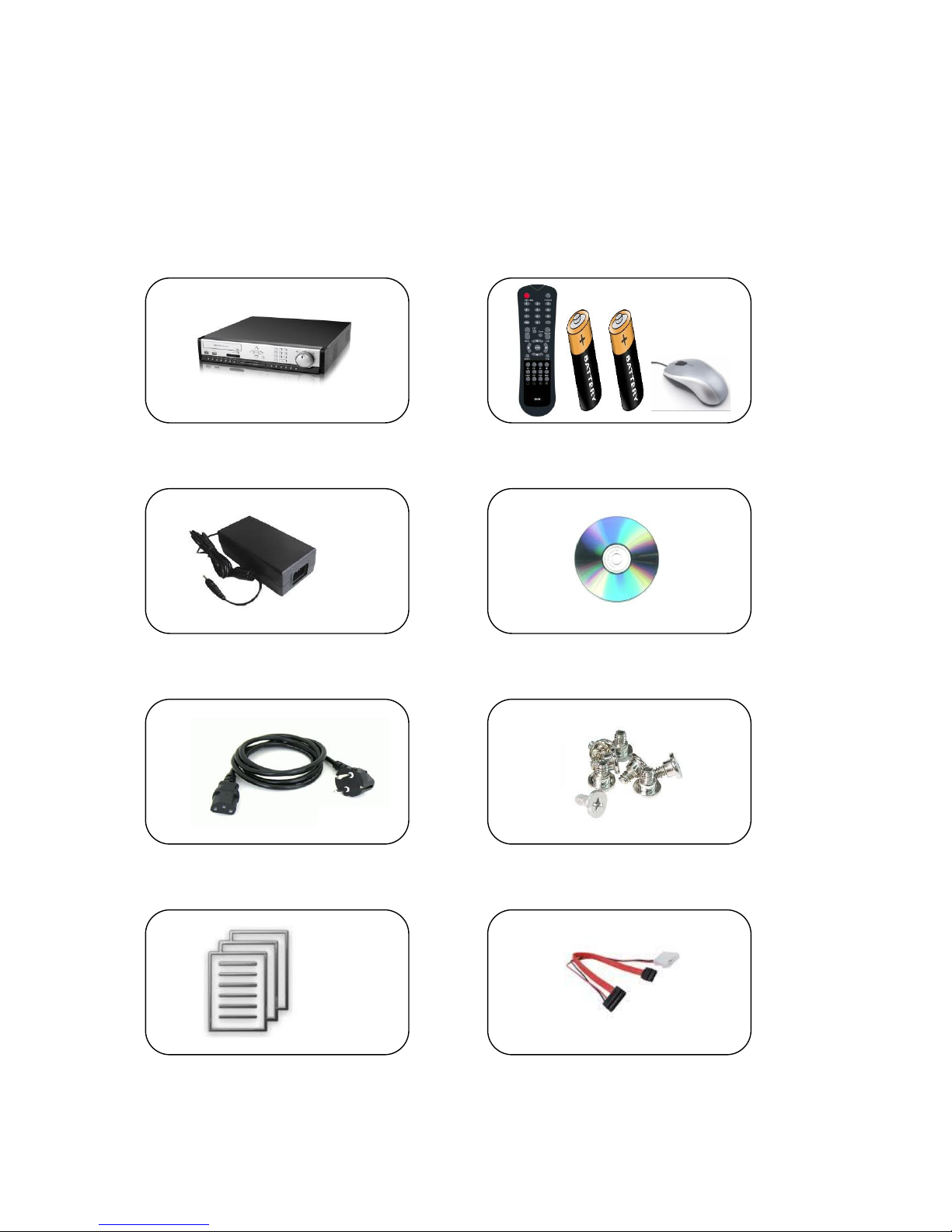
1.1 Packing Contents
The product box has the following contents, if any of these items are missing or damaged,
contact your dealer immediately before using the product.
DVR System Remote Control, Battery & USB Mouse
Power Adapter Software CD
Power Cable HDD Screws
User Manual HDD Cable
7
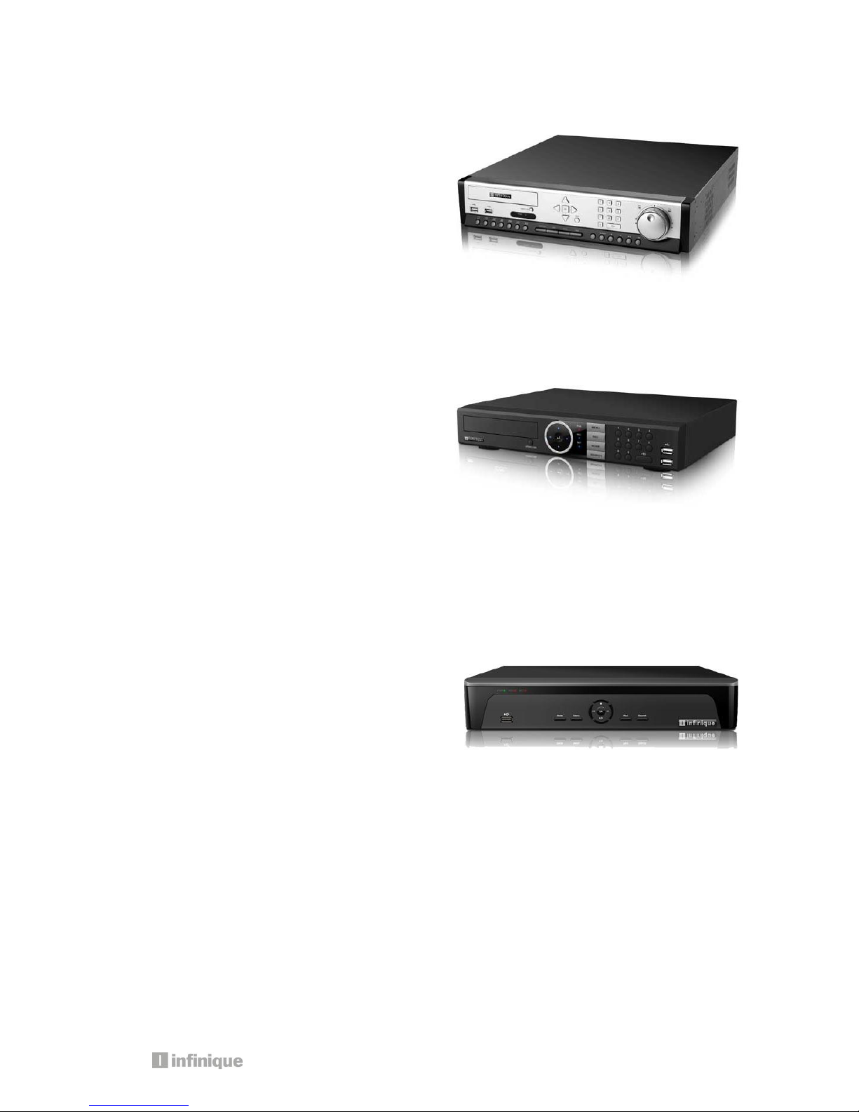
1.2 Product Models
Professional Series Model Numbers
IAR16-48W3I-SE1D: 16 Channel 960H DVR
IAR8-24W3I-SE1D: 8 Channel 960H DVR
960H Real-time Professional Series DVR with 3
SATA disk and DVD RW
System Series Model Numbers
IAR16-48W2I-SE1D – 16 Channel 960H DVR
IAR8-24W2I-SE1D – 8 Channel 960H DVR
IAR4-12W2I-SE1D – 4 Channel 960H DVR
960H Real-time Professional Series DVR with 2
SATA disk and DVD RW
Econo Series Model Numbers
IAR16-24W1I-SE1– 16 Channel 960H DVR
IAR8-24W1I-SE1 – 8 Channel 960H DVR
IAR4-12W1I-SE1 – 4 Channel 960H DVR
960H Real-time Professional Series DVR with 1
SATA disk and DVD RW
6 9 7 8 1 2 5 3 4
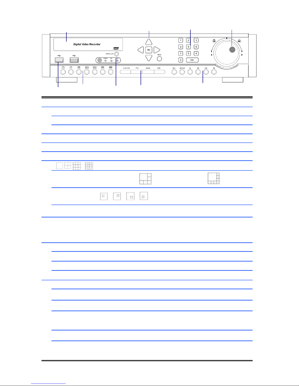
1.3 Front View - Professional Series DVR
1
DVD WRITER
DVD Writer Door
2
DIRECTION
Move the Curosor in MENU
SEL
Select Items
MENU
Go to System setup MENU
3
NUMERIC KEYS
Select Cameras or Input Numbers
4
JOG SHUTTLE
Control playback speed
5
USB PORT
USB Devices(Mouse,Memory Stick,HDD)can be connected
6
Screen Division Mode(1,4,9,16)
POP
POP1: 6CH Mode / POP2: 8CH Mux Mode
PIP
SEQ
(CAM01CAM02CAM03…..CAM16CAM1…..)
7
IR SENSOR/LED
POWER LED : POWER ON -> LED ON
NET LED : Network connected to DVR -> LED ON
REC LED : Recording -> LED ON
8
FUNCTION
Start Menu functions
PTZ
Go to PTZ control mode
ZOOM
ZOOM IN/OUT
OSD
Display/ hide OSD
9
REC
Start/Stop recording
SEARCH
Search recording file during playback mode
■
Stop playback
◀◀
Reverse playback, Step1/2/3,
Playback the previous frame in pause mode
▶I
Play and pause
▶▶
Fast forward playback step1/2/3
Playback the next frame in pause mode
9
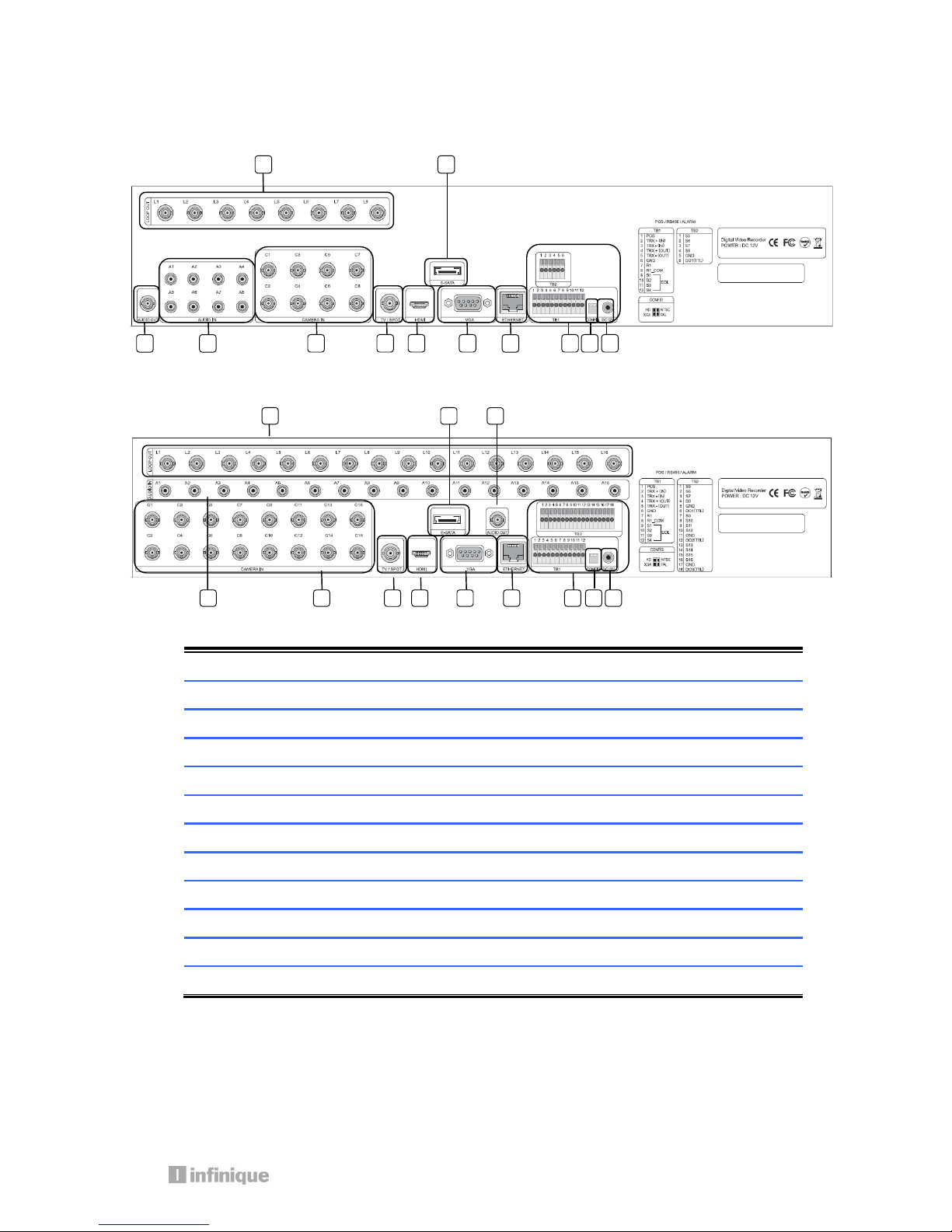
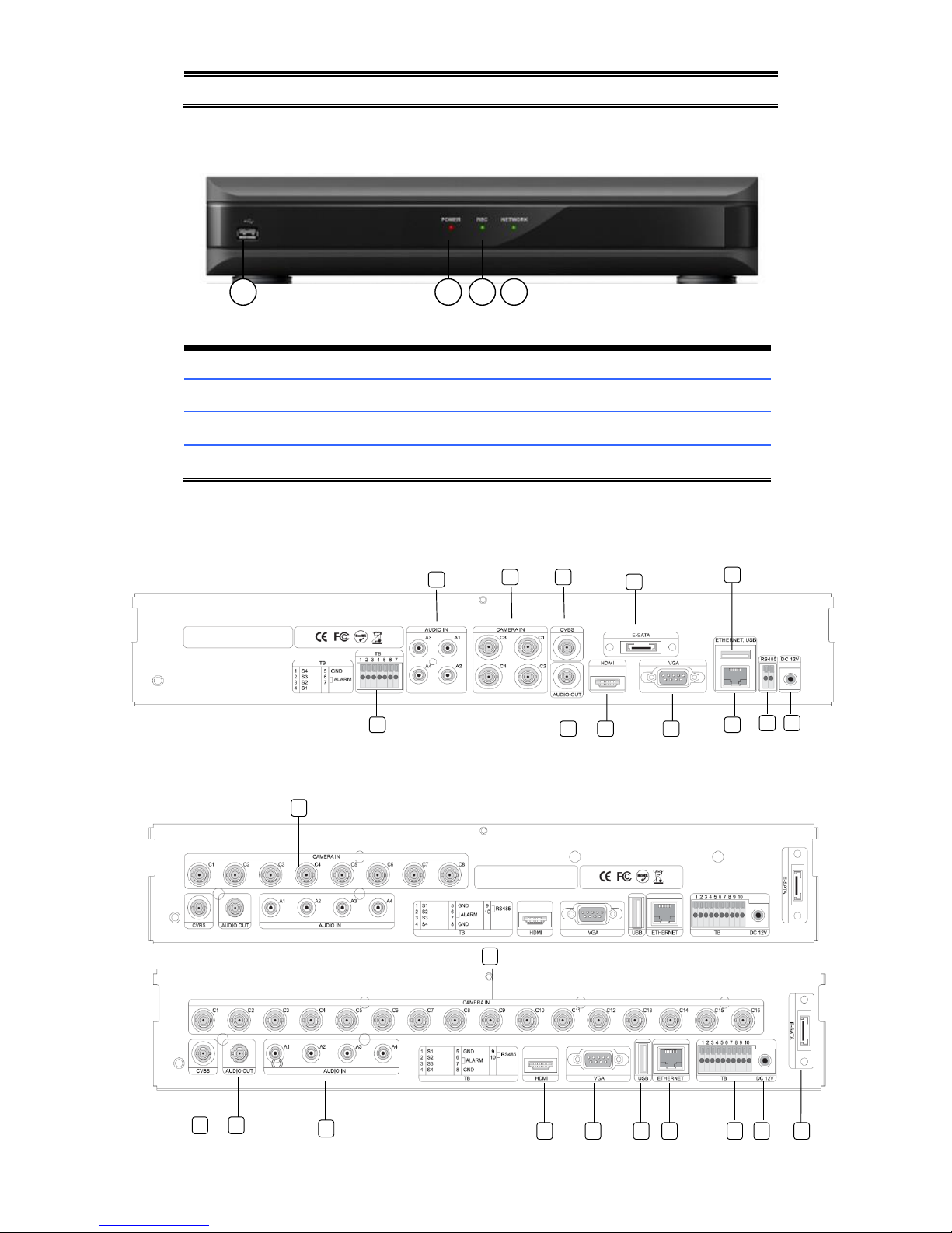
1.4 Rear View - Professional Series DVR
8 Channel DVR
16 Channel DVR
1
LOOP OUT
Video Signal loop-back output connection (BNC)
2
E-SATA
External SATA
3
AUDIO OUT
Audio output (RCA)
4
AUDIO IN
Audio Input Connection (RCA)
5
CAMERA IN
Video Camera Connection (BNC)
6
SPOT /TV
Live or SPOT out (BNC)
7
HDMI
HDMI output (HDMI type-C)
8
VGA
VGA or LCD mitor (D-SUB 15p)
9
ETHERNET
Cable Modem, Ethernet 10/100 Base-T (RJ-45)
10
TERMINAL BLOCK
RS-485 / Sensor In / Relay out / POS 1
11
CONFIG
NTSC/PAL HD/XGA (DIP S/W, 2-pin)
12
DC 12V POWER
5.83A Adaptor
1 2 10 3 4 5 6 7 8 9 11
12
1 2 3 4 5 6 7 8 9
10
11
12
6 7 1 2 5 3 4
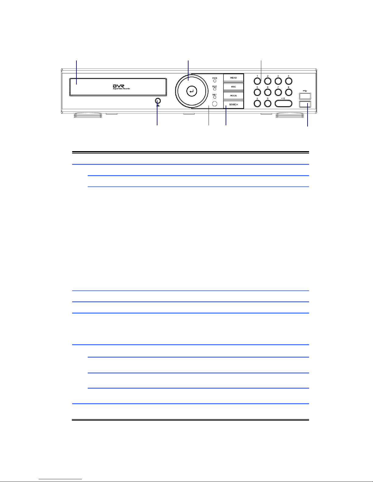
1.5 Front View - System Series DVR
1
DVD WRITER
DVD Writer Door
2
DIRECTION
Move the Curosor in MENU
SEL
Select Items
■
◀◀
▶I
▶▶
For Playback
Stop playback
Fast backward playback
Step backward(Playback the previous frame in pause
mode)
Play and pause
Fast forward playback
Step forward(Playback the next frame in pause mode)
3
NUMERIC KEYS
Select Cameras or Input Numbers
4
DVD EJECT
DVD Door Eject
5
IR SENSOR/LED
POWER LED : POWER ON -> LED ON
NET LED : Network connected to DVR -> LED ON
REC LED : Recording -> LED ON
6
MENU
Go to System setup MENU
REC
Start/Stop recording
MODE
Screen Division Mode
SEARCH
Search recording file during playback mode
7
USB PORT
To connect USB device (Mouse, Memory Stick, HDD)
11
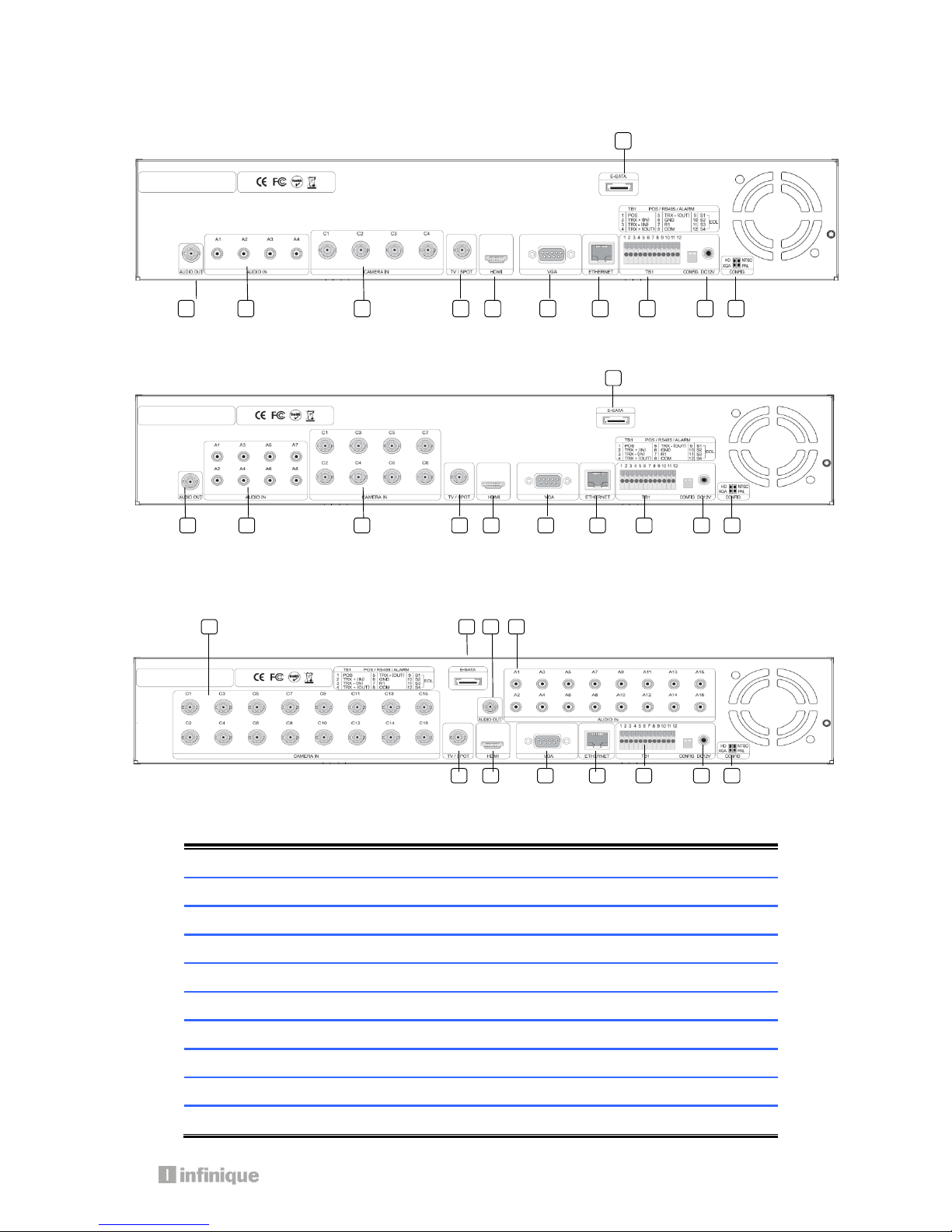
1.6 Rear View - System Series DVR
4 Channel DVR
8 Channel DVR
16 Channel DVR
1
E-SATA
External SATA
2
AUDIO OUT
Audio output (RCA)
3
AUDIO IN
Audio Input Connection (RCA)
4
CAMERA IN
Video Camera Connection (BNC)
5
SPOT /TV
Live or SPOT out (BNC)
6
HDMI
HDMI output (HDMI type-C)
7
VGA
VGA or LCD mitor (D-SUB 15p)
8
ETHERNET
Cable Modem, Ethernet 10/100 Base-T (RJ-45)
9
TERMINAL BLOCK
RS-485 / Sensor In / Relay out / POS 1
10
CONFIG
NTSC/PAL HD/XGA (DIP S/W, 2-pin)
1
2 3 4
5 6 7 8 9
10
11
5
6
7
8
9
10
11 1 2 3 4
5 6 7 8 9
10
11 2 3
4
1
11
DC 12V POWER
5.83A Adaptor
1.7 Front View - Econo Series DVR
1.
USB PORT
USB Devices(Mouse, Memory Stick) can be connected
2.
POWER LED
The Light turned on when Power is on
3.
REC LED
The Light turned on while DVR records something
4.
NETWORK LED
The Light turned on during network connection
1.8 Rear View - Econo Series DVR
4 Channel DVR
8 Channel DVR / 16Channel DVR
4
1 2 3
1
2 3 4
5
6
7 8 11
12
13
4
5
6
7
8 9 10
13 2 3 4 1
12
13
1
E-SATA
External SATA
2
AUDIO OUT
Audio output (RCA)
3
AUDIO IN
Audio Input Connection (RCA)
4
CAMERA IN
Video Camera Connection (BNC)
5
SPOT /TV
Live or SPOT out (BNC)
6
HDMI
HDMI output (HDMI type-C)
7
VGA
VGA or LCD mitor (D-SUB 15p)
8
ETHERNET
Cable Modem, Ethernet 10/100 Base-T (RJ-45)
9
TERMINAL
BLOCK(4CHANNEL)
Sensor In (1~4:+, 5:GND) / Relay out (6:+ / 7:GND)
10
RS-485(4CHANNEL)
For connection of RS-485 communication
11
TERMINAL BOLCK
(8CHANNEL
/16CHANNEL)
Sensor In (1~4:+, 5:GND) / Relay out (6,7:+ / 8:GND) /
RS-485 (9:+/10:GND)
12
USB PORT
USB Devices(Mouse, Memory Stick) can be connected
13
DC 12V POWER
3A Adaptor
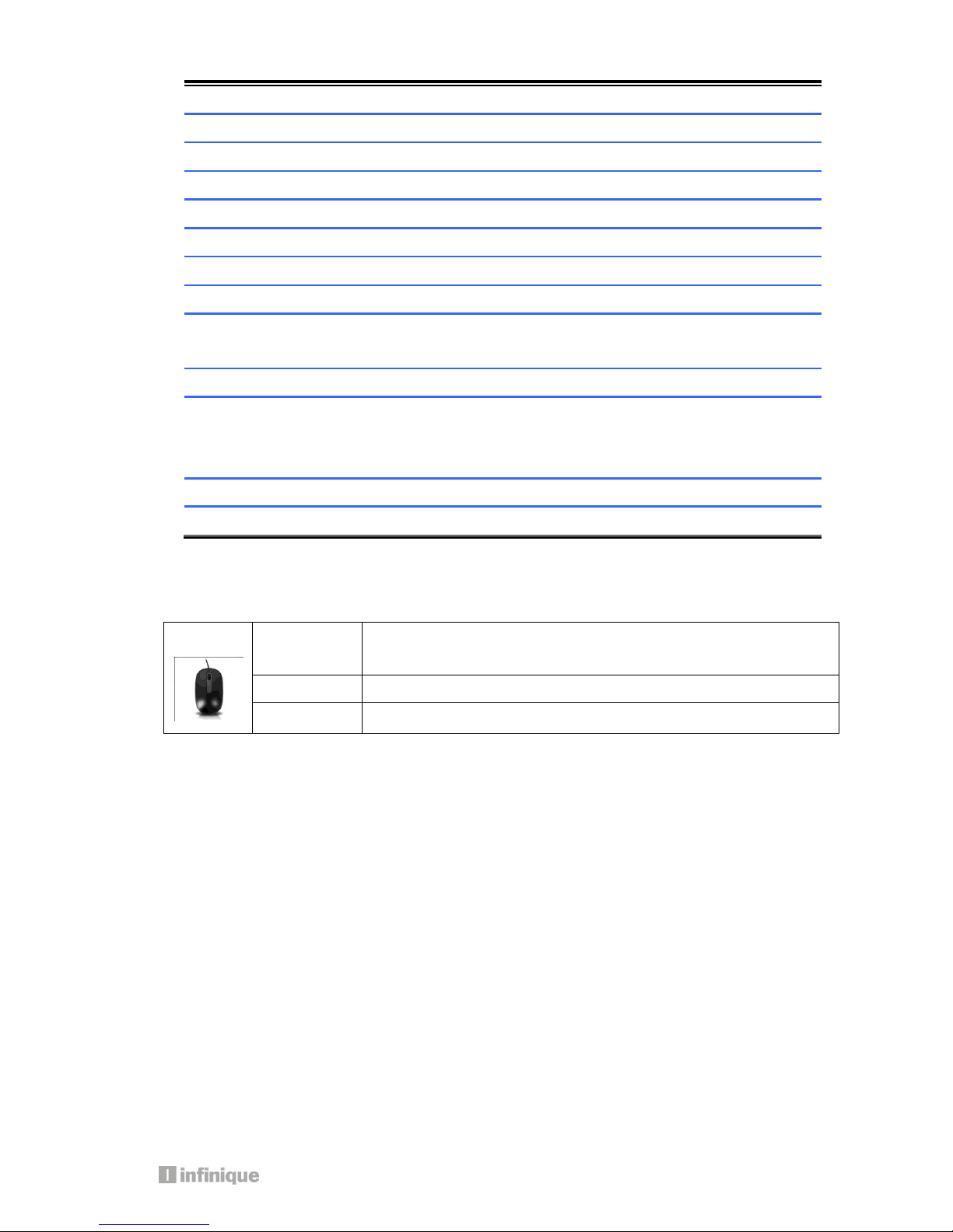
1.9 Mouse
A mouse is connected to the front or rear USB ports.
Left Click
Popup Login window/Selecting Icons/Its values
Selecting sub-menu in setup menu and values in each menu
Right Click
Popup Main Menu/Back from menu to live mode
Double click
Change one ch to multi ch or multi ch to one ch mode.
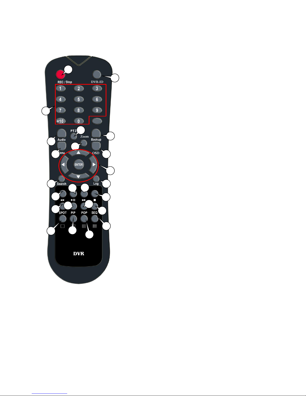
1.10 Remote Control
1) REC: Record button
2) DVR-ID: Used when controlling more than one DVR
3) Number Buttons
4) AUDIO: Audio ON / Mute
5) BACKUP: Back up recorded data to other device
6) MENU: Activate MENU mode for setup
7) OSD: Show or Hide OSD
8) PTZ: Control Pan/Tilt/Zoom camera.
9) Digital Zoom
10) Navigation Keys (▲,▼,◀,▶)
Move cursor or control PTZ camera
ENTER
Select sub item in system setup mode
11) SEARCH: Search recorded video
12) LOG: Show running status of DVR system
13) ◀◀: Reverse Play
14) ▶I: Play or Pause during playback
15) ▶▶: Fast Forward Play
16) ■: Stop Playback and go to Live mode
17) SPOT: Not Operated in this model
18) PIP: Go to PIP mode
19) POP: Enlarge specific channel in Live mode
20) SEQ: Show each camera rotation
21) Full screen mode
22) Quad screen mode
23) 9 Division screen mode
Operated only for 8ch or 16 channels
24) 16 Division screen mode
Operated only for 16 channels
1 3 4 7 6 8 10
11
9
13
12
14
17
22
19
16
15 2 5
21
23
24
18
20
15
2. Installing DVR
2.1 Installing HDD
One HDD should be installed inside the DVR to record the video.
If HDD is not installed in the product, please install HDD first as follows.
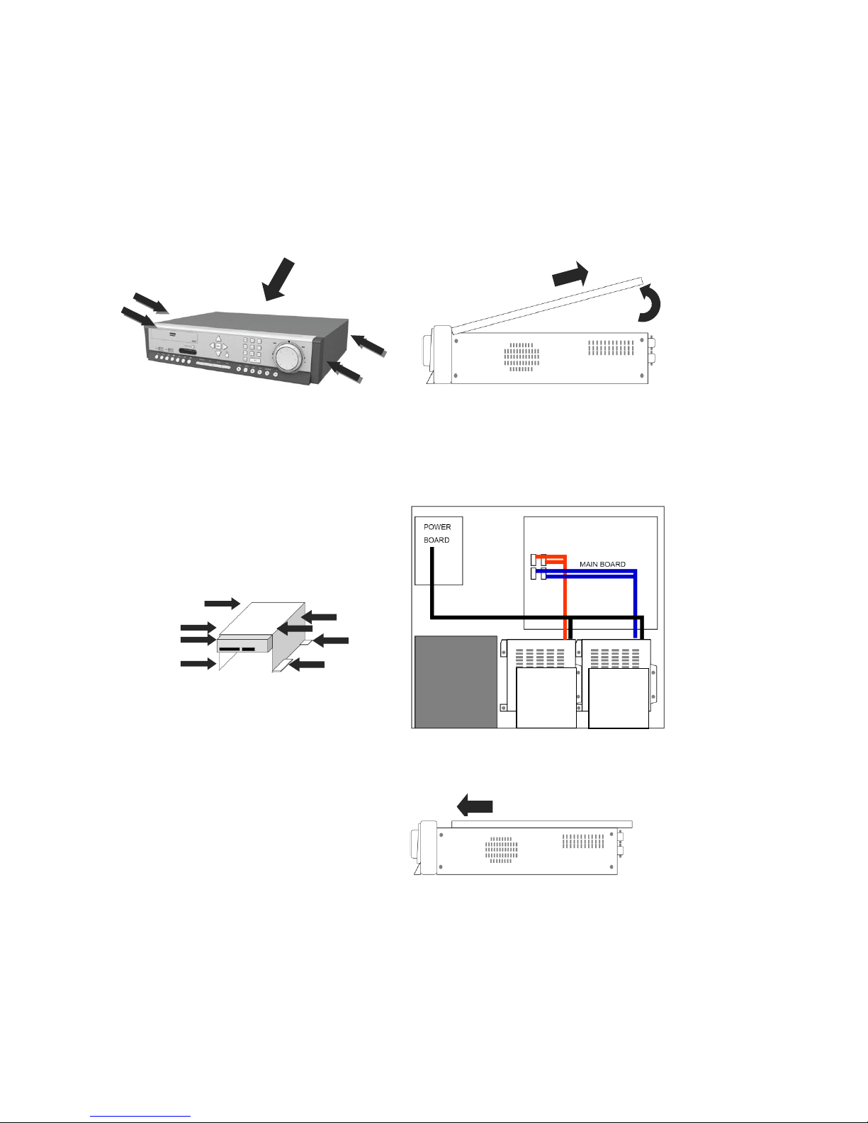
During installation, please take care from any sharp edges of the product
(1) Loosen screws on both sides and back
of DVR to detach the DVR cover
(2) Lift the end of top cover and pull it out
from DVR
(3) Loosen screws of HDD bracket to
detach from DVR. Put HDD in HDD bracket
and tighten with the supplied HDD screws
to bracket
(4) Restore HDD bracket to DVR and
connect HDD power cable and data
cable to HDD
(5) Insert top cover of DVR as per the
picture and tighten the screws again
2
1
HDD1
HDD2
HDD3
HDD4
17
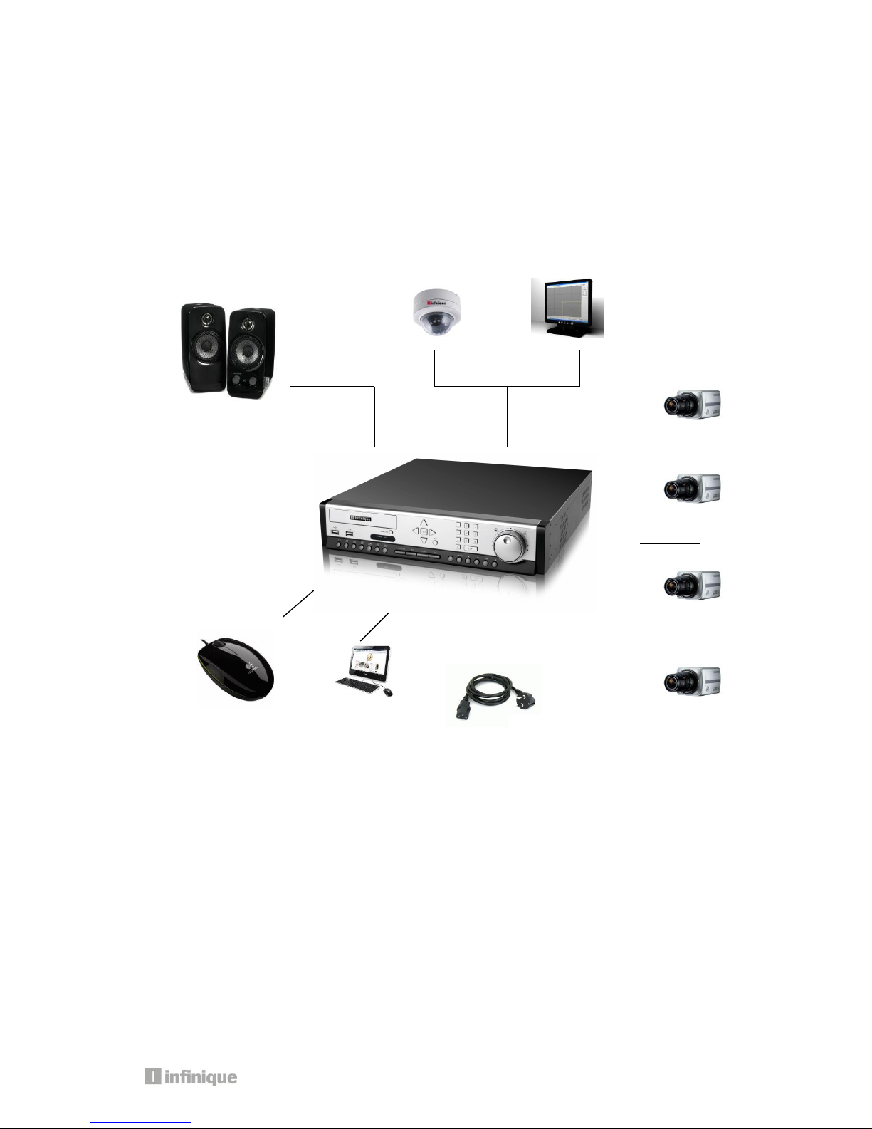
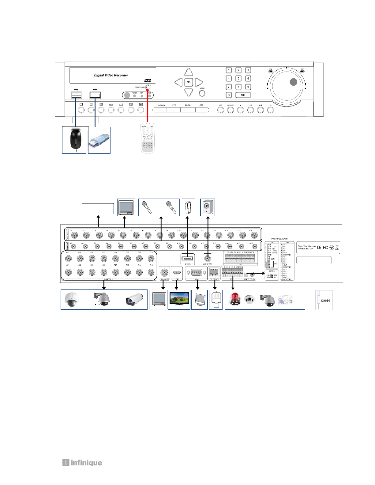
2.2 Connecting Devices to the DVR
2.2.1. Front
2.2.2. Rear
2.2.3. Connection of main devices
1) Adaptor
The adaptor supplied together with product is to be used. Third party adaptors can do
serious damages to the DVR.
2) Camera
Connect BNC video signal cable into [CAMERA IN] port on rear of the product. Please
connect the camera to the DVR when the DVR is off.
3) Audio, Sensor, Alarm, and RS-485
Sensor device should be connected to S and G port.
Alarm devices should be connected to A and G port.
The type of Alarm (NC/NO) has to be selected in DVR MENU in accordance with alarm
device.
PTZ camera or keyboard control is connected to RS-485(+,-) port. Please be careful not
. . . . . .
Loop out
. . . . . .. . . . .

to connect it to different polarity lest the device will fail to work.
4) Video Out
3 kinds of Video (HDMI, VGA, BNC) are supported by DVRs.
BNC is used for Live or Spot Monitoring.
When Video out is connected to VGA port of Monitor, the monitor resolution is either
1920 * 1080 or 1024 *768.
Please check CONFIG S/W in rear side for HD(1920*1080) or XGA(1024*768)
5) E-SATA
Some brands of E-SATA HDD Racks are not supported.
Please check whether HDD Rack is supported or not before usage.
6) USB Port
USB Mouse, USB memory stick, USB HDD, or external ODD drive can be connected to USB
port.
Note: External USB ODD doesn’t support multisession format, please check the CD
capacity and backup data capacity first before you backup recorded data to CD.
7) Ethernet Port
It is used to connect DVR to PC or LAN
3. Operation
19
Important: Please install a hard drive before using the DVR
3.1. Turning on
There is no power switch for the DVR. So, please connect all devices to DVR before it is
turned on.
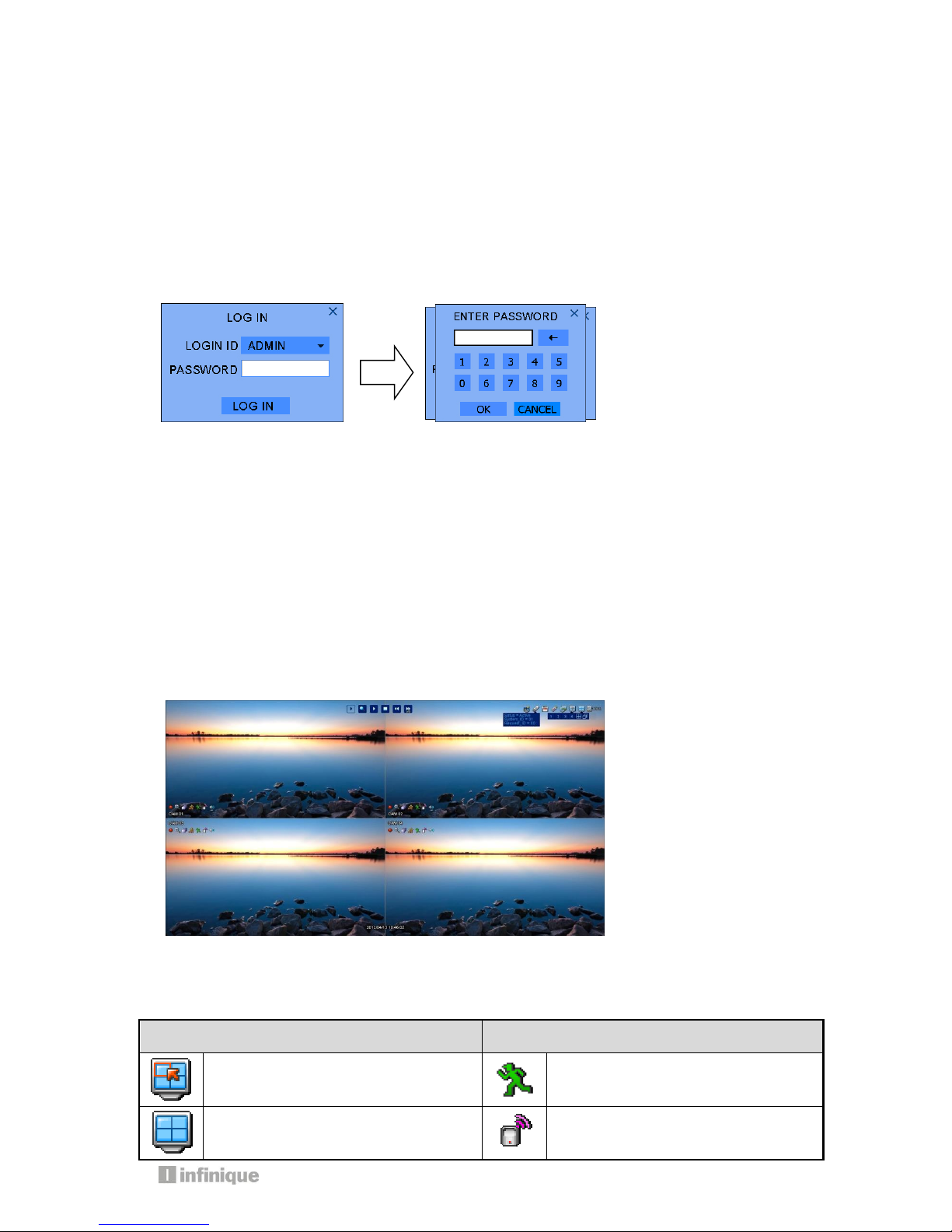
3.2 Log in
The log-in window will pop up after booting is over.
Please move the pointer into password window with mouse or up/down key of remote
controller, and then press enter button in remote control or right button of mouse.
Please enter default password (0000) in password window, and click OK icon and then
LOGIN icon.
It is ready to be accessable to DVR.
If you want to change password, please refer the [MENU-SETUP-SYSTEM-USER].
3.3 Screen Layout
You can see the below items according to your selection on function.
3.3.1 Icons in Live Mode
In Live display mode, icons will be indicated to notify the system mode or status.
Below are the icon categories, which are indicated on the monitor.
Icon for system
Icon for each channel
Selects specific 1ch with full screen
When Motion Detected
Screen-Division mode
When Sensor Activated
 Loading...