

Infinera ATN Hardware Description Manual

Infinera ATN
Hardware Description Guide
Release 1.0
Version 001
Document ID 1900-422
Infinera Corporation
169 Java Drive
Sunnyvale, CA 94089
www.infinera.com
+ 1-408-572-5200
- Please refer to the Infinera Customer Service Website for the most recent version of this document -

Copyright
© Copyright 2009 Infinera Corporation. All rights reserved.
This Manual is the property of Infinera Corporation and is confidential. No part of this Manual may be reproduced for any purposes or
transmitted in any form to any third party without the express written consent of Infinera.
Infinera makes no warranties or representations, expressed or implied, of any kind relative to the information or any portion thereof
contained in this Manual or its adaptation or use, and assumes no responsibility or liability of any kind, including, but not limited to,
indirect, special, consequential or incidental damages, (1) for any errors or inaccuracies contained in the information or (2) arising
from the adaptation or use of the information or any portion thereof including any application of software referenced or utilized in the
Manual. The information in this Manual is subject to change without notice.
Trademarks
Infinera, Infinera Digital Optical Networks, I-PIC, IQ, DTN, ATN and logos that contain Infinera are trademarks or registered
trademarks of Infinera Corporation in the United States and other countries.
All other trademarks in this Manual are the property of their respective owners.
Infinera ATN, DTN and Infinera Optical Line Amplifier Regulatory Compliance
FCC Class A
This device complies with Part 15 of the FCC rules. Operation is subject to the following two conditions: (1) this device may not cause
harmful interference, and (2) this device must accept any interference received, including interference that may cause undesired
operation. Modifying the equipment without Infinera's written authorization may result in the equipment no longer complying with FCC
requirements for Class A digital devices. In that event, your right to use the equipment may be limited by FCC regulations, and you
may be required to correct any interference to radio or television communications at your own expense.
DOC Class A
This digital apparatus does not exceed the Class A limits for radio noise emissions from digital apparatus as set out in the
interference-causing equipment standard titled “Digital Apparatus," ICES-003 of the Department of Communications.
Cet appareil numérique respecte les limites de bruits radioélectriques applicables aux appareils numériques de Classe A prescrites
dans la norme sur le matériel brouilleur: "Appareils Numériques," NMB-003 édictée par le Ministère des Communications.
Warning
This is a class A product. In a domestic environment this product may cause radio interference in which case the user may be
required to take adequate measures.
FDA
This product complies with the DHHS Rules 21 CFR Subchapter J, Section 1040.10, Applicable at date of manufacture.

Contents
About this Document
Objective. . . . . . . . . . . . . . . . . . . . . . . . . . . . . . . . . . . . . . . . . . . . . . . . . . . . . . . . . . . . . . . . . . . . . . . . . . . . . . . . xiii
Audience. . . . . . . . . . . . . . . . . . . . . . . . . . . . . . . . . . . . . . . . . . . . . . . . . . . . . . . . . . . . . . . . . . . . . . . . . . . . . . . . xiii
Document Organization . . . . . . . . . . . . . . . . . . . . . . . . . . . . . . . . . . . . . . . . . . . . . . . . . . . . . . . . . . . . . . . . . . . . xiv
Documents for Release 1.0 . . . . . . . . . . . . . . . . . . . . . . . . . . . . . . . . . . . . . . . . . . . . . . . . . . . . . . . . . . . . . . . . . xv
Technical Assistance. . . . . . . . . . . . . . . . . . . . . . . . . . . . . . . . . . . . . . . . . . . . . . . . . . . . . . . . . . . . . . . . . . . . . . . xvi
Documentation Feedback . . . . . . . . . . . . . . . . . . . . . . . . . . . . . . . . . . . . . . . . . . . . . . . . . . . . . . . . . . . . . . . . . . . xvi
Chapter 1 - Introduction
Infinera Digital Optical Network. . . . . . . . . . . . . . . . . . . . . . . . . . . . . . . . . . . . . . . . . . . . . . . . . . . . . . . . . . . . . . 1-2
Infinera ATN . . . . . . . . . . . . . . . . . . . . . . . . . . . . . . . . . . . . . . . . . . . . . . . . . . . . . . . . . . . . . . . . . . . . . . . . . 1-2
Infinera Dispersion Management Chassis . . . . . . . . . . . . . . . . . . . . . . . . . . . . . . . . . . . . . . . . . . . . . . . . . . 1-3
Infinera DTN . . . . . . . . . . . . . . . . . . . . . . . . . . . . . . . . . . . . . . . . . . . . . . . . . . . . . . . . . . . . . . . . . . . . . . . . . 1-3
Infinera Optical Line Amplifier . . . . . . . . . . . . . . . . . . . . . . . . . . . . . . . . . . . . . . . . . . . . . . . . . . . . . . . . . . . . 1-3
Release 1.0 Feature Summary. . . . . . . . . . . . . . . . . . . . . . . . . . . . . . . . . . . . . . . . . . . . . . . . . . . . . . . . . . . . . . 1-4
Chapter 2 - Infinera ATN
ATC System Specifications . . . . . . . . . . . . . . . . . . . . . . . . . . . . . . . . . . . . . . . . . . . . . . . . . . . . . . . . . . . . . . . . . 2-2
ATC Power Consumption . . . . . . . . . . . . . . . . . . . . . . . . . . . . . . . . . . . . . . . . . . . . . . . . . . . . . . . . . . . . . . . 2-2
ATC Compliancy . . . . . . . . . . . . . . . . . . . . . . . . . . . . . . . . . . . . . . . . . . . . . . . . . . . . . . . . . . . . . . . . . . . . . . 2-3
ATC Technical Specifications . . . . . . . . . . . . . . . . . . . . . . . . . . . . . . . . . . . . . . . . . . . . . . . . . . . . . . . . . . . . 2-4
ATC Overview. . . . . . . . . . . . . . . . . . . . . . . . . . . . . . . . . . . . . . . . . . . . . . . . . . . . . . . . . . . . . . . . . . . . . . . . . . . 2-5
Front View. . . . . . . . . . . . . . . . . . . . . . . . . . . . . . . . . . . . . . . . . . . . . . . . . . . . . . . . . . . . . . . . . . . . . . . . . . . 2-5
ATC Thermal Loading . . . . . . . . . . . . . . . . . . . . . . . . . . . . . . . . . . . . . . . . . . . . . . . . . . . . . . . . . . . . . . . . . . . . . 2-7
Infinera Corporation
ATN Hardware Description Guide Release 1.0
Infinera Proprietary and Confidential

Page ii
ATC Product Details . . . . . . . . . . . . . . . . . . . . . . . . . . . . . . . . . . . . . . . . . . . . . . . . . . . . . . . . . . . . . . . . . . . . . 2-13
Functional Description. . . . . . . . . . . . . . . . . . . . . . . . . . . . . . . . . . . . . . . . . . . . . . . . . . . . . . . . . . . . . . . . . 2-13
Mechanical Specifications . . . . . . . . . . . . . . . . . . . . . . . . . . . . . . . . . . . . . . . . . . . . . . . . . . . . . . . . . . . . . . 2-14
Rack Mounting Ears . . . . . . . . . . . . . . . . . . . . . . . . . . . . . . . . . . . . . . . . . . . . . . . . . . . . . . . . . . . . . . . . . . 2-16
Power Conversion Module (PCM). . . . . . . . . . . . . . . . . . . . . . . . . . . . . . . . . . . . . . . . . . . . . . . . . . . . . . . . 2-16
DC Power Conversion Module (PCM-48VDC) . . . . . . . . . . . . . . . . . . . . . . . . . . . . . . . . . . . . . . . . . . . 2-17
External Indicators . . . . . . . . . . . . . . . . . . . . . . . . . . . . . . . . . . . . . . . . . . . . . . . . . . . . . . . . . . . . . . 2-17
Power LEDs . . . . . . . . . . . . . . . . . . . . . . . . . . . . . . . . . . . . . . . . . . . . . . . . . . . . . . . . . . . . . . . . . . . 2-18
Connectors. . . . . . . . . . . . . . . . . . . . . . . . . . . . . . . . . . . . . . . . . . . . . . . . . . . . . . . . . . . . . . . . . . . . 2-18
Technical Specifications . . . . . . . . . . . . . . . . . . . . . . . . . . . . . . . . . . . . . . . . . . . . . . . . . . . . . . . . . 2-19
Power Distribution Architecture . . . . . . . . . . . . . . . . . . . . . . . . . . . . . . . . . . . . . . . . . . . . . . . . . . . . 2-19
Alarm Panel. . . . . . . . . . . . . . . . . . . . . . . . . . . . . . . . . . . . . . . . . . . . . . . . . . . . . . . . . . . . . . . . . . . . . . . . . 2-20
Chassis-Level Alarm LEDs . . . . . . . . . . . . . . . . . . . . . . . . . . . . . . . . . . . . . . . . . . . . . . . . . . . . . . . . . . 2-20
Alarm Cutoff (ACO) Indicators. . . . . . . . . . . . . . . . . . . . . . . . . . . . . . . . . . . . . . . . . . . . . . . . . . . . . . . . 2-21
External Connectors . . . . . . . . . . . . . . . . . . . . . . . . . . . . . . . . . . . . . . . . . . . . . . . . . . . . . . . . . . . . . . . 2-21
Technical Specifications . . . . . . . . . . . . . . . . . . . . . . . . . . . . . . . . . . . . . . . . . . . . . . . . . . . . . . . . . 2-22
Alarm Input Contact Pin Assignments . . . . . . . . . . . . . . . . . . . . . . . . . . . . . . . . . . . . . . . . . . . . . . . 2-22
Alarm Output Contact Pin Assignments. . . . . . . . . . . . . . . . . . . . . . . . . . . . . . . . . . . . . . . . . . . . . . 2-23
Fan Tray . . . . . . . . . . . . . . . . . . . . . . . . . . . . . . . . . . . . . . . . . . . . . . . . . . . . . . . . . . . . . . . . . . . . . . . . . . . 2-26
Technical Specifications. . . . . . . . . . . . . . . . . . . . . . . . . . . . . . . . . . . . . . . . . . . . . . . . . . . . . . . . . . . . . 2-27
Air Filter . . . . . . . . . . . . . . . . . . . . . . . . . . . . . . . . . . . . . . . . . . . . . . . . . . . . . . . . . . . . . . . . . . . . . . . . . . . . 2-27
Mechanical Specifications . . . . . . . . . . . . . . . . . . . . . . . . . . . . . . . . . . . . . . . . . . . . . . . . . . . . . . . . . . . 2-27
Fiber Management Guide and Cable Guides . . . . . . . . . . . . . . . . . . . . . . . . . . . . . . . . . . . . . . . . . . . . . . . 2-28
Fiber Management Guide . . . . . . . . . . . . . . . . . . . . . . . . . . . . . . . . . . . . . . . . . . . . . . . . . . . . . . . . . . . 2-29
Cable Management Guides . . . . . . . . . . . . . . . . . . . . . . . . . . . . . . . . . . . . . . . . . . . . . . . . . . . . . . . . . . 2-30
Card Cage . . . . . . . . . . . . . . . . . . . . . . . . . . . . . . . . . . . . . . . . . . . . . . . . . . . . . . . . . . . . . . . . . . . . . . . . . . 2-31
ATC-A Card Cage . . . . . . . . . . . . . . . . . . . . . . . . . . . . . . . . . . . . . . . . . . . . . . . . . . . . . . . . . . . . . . . . . 2-31
ATC-P Card Cage . . . . . . . . . . . . . . . . . . . . . . . . . . . . . . . . . . . . . . . . . . . . . . . . . . . . . . . . . . . . . . . . . 2-32
ATN Management Module (AMM). . . . . . . . . . . . . . . . . . . . . . . . . . . . . . . . . . . . . . . . . . . . . . . . . . . . . . . . . . . 2-34
Functional Description. . . . . . . . . . . . . . . . . . . . . . . . . . . . . . . . . . . . . . . . . . . . . . . . . . . . . . . . . . . . . . . . . 2-34
Block Diagram . . . . . . . . . . . . . . . . . . . . . . . . . . . . . . . . . . . . . . . . . . . . . . . . . . . . . . . . . . . . . . . . . . . . . . . 2-35
External Indicators and Connectors . . . . . . . . . . . . . . . . . . . . . . . . . . . . . . . . . . . . . . . . . . . . . . . . . . . . . . 2-36
Circuit Pack Level LEDs . . . . . . . . . . . . . . . . . . . . . . . . . . . . . . . . . . . . . . . . . . . . . . . . . . . . . . . . . . . . 2-36
Connectors . . . . . . . . . . . . . . . . . . . . . . . . . . . . . . . . . . . . . . . . . . . . . . . . . . . . . . . . . . . . . . . . . . . . . . 2-37
Port Indicators . . . . . . . . . . . . . . . . . . . . . . . . . . . . . . . . . . . . . . . . . . . . . . . . . . . . . . . . . . . . . . . . . . . . 2-37
Technical Specifications . . . . . . . . . . . . . . . . . . . . . . . . . . . . . . . . . . . . . . . . . . . . . . . . . . . . . . . . . . . . . . . 2-37
ATN Amplifier Module (AAM) . . . . . . . . . . . . . . . . . . . . . . . . . . . . . . . . . . . . . . . . . . . . . . . . . . . . . . . . . . . . . . 2-39
Functional Description. . . . . . . . . . . . . . . . . . . . . . . . . . . . . . . . . . . . . . . . . . . . . . . . . . . . . . . . . . . . . . . . . 2-39
Block Diagram . . . . . . . . . . . . . . . . . . . . . . . . . . . . . . . . . . . . . . . . . . . . . . . . . . . . . . . . . . . . . . . . . . . . . . . 2-39
External Indicators and Connectors . . . . . . . . . . . . . . . . . . . . . . . . . . . . . . . . . . . . . . . . . . . . . . . . . . . . . . 2-40
Circuit Pack Level LEDs . . . . . . . . . . . . . . . . . . . . . . . . . . . . . . . . . . . . . . . . . . . . . . . . . . . . . . . . . . . . 2-41
Connectors . . . . . . . . . . . . . . . . . . . . . . . . . . . . . . . . . . . . . . . . . . . . . . . . . . . . . . . . . . . . . . . . . . . . . . 2-41
Technical Specifications . . . . . . . . . . . . . . . . . . . . . . . . . . . . . . . . . . . . . . . . . . . . . . . . . . . . . . . . . . . . . . . 2-42
Optical Specifications . . . . . . . . . . . . . . . . . . . . . . . . . . . . . . . . . . . . . . . . . . . . . . . . . . . .
. . . . . . . . . . . . . 2-42
Contents
ATN Hardware Description Guide Release 1.0
Infinera Proprietary and Confidential
Infinera Corporation

Page iiiContents
Optical Filter Modules (OFM) . . . . . . . . . . . . . . . . . . . . . . . . . . . . . . . . . . . . . . . . . . . . . . . . . . . . . . . . . . . . . . 2-43
10-Channel DWDM OFMs . . . . . . . . . . . . . . . . . . . . . . . . . . . . . . . . . . . . . . . . . . . . . . . . . . . . . . . . . . . . . 2-45
Functional Description . . . . . . . . . . . . . . . . . . . . . . . . . . . . . . . . . . . . . . . . . . . . . . . . . . . . . . . . . . . . . . 2-45
Block Diagram . . . . . . . . . . . . . . . . . . . . . . . . . . . . . . . . . . . . . . . . . . . . . . . . . . . . . . . . . . . . . . . . . . . . 2-46
External Connectors . . . . . . . . . . . . . . . . . . . . . . . . . . . . . . . . . . . . . . . . . . . . . . . . . . . . . . . . . . . . . . . 2-48
Connectors . . . . . . . . . . . . . . . . . . . . . . . . . . . . . . . . . . . . . . . . . . . . . . . . . . . . . . . . . . . . . . . . . . . . . . 2-49
Technical Specifications. . . . . . . . . . . . . . . . . . . . . . . . . . . . . . . . . . . . . . . . . . . . . . . . . . . . . . . . . . . . . 2-55
Optical Specifications . . . . . . . . . . . . . . . . . . . . . . . . . . . . . . . . . . . . . . . . . . . . . . . . . . . . . . . . . . . . . . 2-56
Cascaded 10-channel DWDM Optical Filter Modules . . . . . . . . . . . . . . . . . . . . . . . . . . . . . . . . . . . . . . 2-57
4-Channel DWDM OFMs . . . . . . . . . . . . . . . . . . . . . . . . . . . . . . . . . . . . . . . . . . . . . . . . . . . . . . . . . . . . . . 2-59
Functional Description . . . . . . . . . . . . . . . . . . . . . . . . . . . . . . . . . . . . . . . . . . . . . . . . . . . . . . . . . . . . . . 2-59
Block Diagram . . . . . . . . . . . . . . . . . . . . . . . . . . . . . . . . . . . . . . . . . . . . . . . . . . . . . . . . . . . . . . . . . . . . 2-59
External Connectors . . . . . . . . . . . . . . . . . . . . . . . . . . . . . . . . . . . . . . . . . . . . . . . . . . . . . . . . . . . . . . . 2-61
Connectors . . . . . . . . . . . . . . . . . . . . . . . . . . . . . . . . . . . . . . . . . . . . . . . . . . . . . . . . . . . . . . . . . . . . . . 2-61
Technical Specifications. . . . . . . . . . . . . . . . . . . . . . . . . . . . . . . . . . . . . . . . . . . . . . . . . . . . . . . . . . . . . 2-66
Optical Specifications . . . . . . . . . . . . . . . . . . . . . . . . . . . . . . . . . . . . . . . . . . . . . . . . . . . . . . . . . . . . . . 2-67
8-channel CWDM OFM . . . . . . . . . . . . . . . . . . . . . . . . . . . . . . . . . . . . . . . . . . . . . . . . . . . . . . . . . . . . . . . . 2-68
Functional Description . . . . . . . . . . . . . . . . . . . . . . . . . . . . . . . . . . . . . . . . . . . . . . . . . . . . . . . . . . . . . . 2-68
Block Diagram . . . . . . . . . . . . . . . . . . . . . . . . . . . . . . . . . . . . . . . . . . . . . . . . . . . . . . . . . . . . . . . . . . . . 2-68
External Connectors . . . . . . . . . . . . . . . . . . . . . . . . . . . . . . . . . . . . . . . . . . . . . . . . . . . . . . . . . . . . . . . 2-69
Connectors . . . . . . . . . . . . . . . . . . . . . . . . . . . . . . . . . . . . . . . . . . . . . . . . . . . . . . . . . . . . . . . . . . . . . . 2-69
Technical Specifications. . . . . . . . . . . . . . . . . . . . . . . . . . . . . . . . . . . . . . . . . . . . . . . . . . . . . . . . . . . . . 2-71
Optical Specifications . . . . . . . . . . . . . . . . . . . . . . . . . . . . . . . . . . . . . . . . . . . . . . . . . . . . . . . . . . . . . . 2-71
2-channel CWDM OFMs . . . . . . . . . . . . . . . . . . . . . . . . . . . . . . . . . . . . . . . . . . . . . . . . . . . . . . . . . . . . . . . 2-72
Functional Description . . . . . . . . . . . . . . . . . . . . . . . . . . . . . . . . . . . . . . . . . . . . . . . . . . . . . . . . . . . . . . 2-72
Block Diagram . . . . . . . . . . . . . . . . . . . . . . . . . . . . . . . . . . . . . . . . . . . . . . . . . . . . . . . . . . . . . . . . . . . . 2-72
External Connectors . . . . . . . . . . . . . . . . . . . . . . . . . . . . . . . . . . . . . . . . . . . . . . . . . . . . . . . . . . . . . . . 2-73
Connectors . . . . . . . . . . . . . . . . . . . . . . . . . . . . . . . . . . . . . . . . . . . . . . . . . . . . . . . . . . . . . . . . . . . . . . 2-73
Technical Specifications. . . . . . . . . . . . . . . . . . . . . . . . . . . . . . . . . . . . . . . . . . . . . . . . . . . . . . . . . . . . . 2-74
Optical Specifications . . . . . . . . . . . . . . . . . . . . . . . . . . . . . . . . . . . . . . . . . . . . . . . . . . . . . . . . . . . . . . 2-75
Passive OSC Add/Drop Module . . . . . . . . . . . . . . . . . . . . . . . . . . . . . . . . . . . . . . . . . . . . . . . . . . . . . . . . . . . . 2-76
Block Diagram . . . . . . . . . . . . . . . . . . . . . . . . . . . . . . . . . . . . . . . . . . . . . . . . . . . . . . . . . . . . . . . . . . . . 2-76
External Indicators and Connectors. . . . . . . . . . . . . . . . . . . . . . . . . . . . . . . . . . . . . . . . . . . . . . . . . . . . 2-76
Connectors . . . . . . . . . . . . . . . . . . . . . . . . . . . . . . . . . . . . . . . . . . . . . . . . . . . . . . . . . . . . . . . . . . . . . . 2-77
Technical Specifications. . . . . . . . . . . . . . . . . . . . . . . . . . . . . . . . . . . . . . . . . . . . . . . . . . . . . . . . . . . . . 2-77
Optical Specifications . . . . . . . . . . . . . . . . . . . . . . . . . . . . . . . . . . . . . . . . . . . . . . . . . . . . . . . . . . . . . . 2-78
Service Interface Module (SIM). . . . . . . . . . . . . . . . . . . . . . . . . . . . . . . . . . . . . . . . . . . . . . . . . . . . . . . . . . . . . 2-79
SIM Module 10G (SIM-T-1-10G) . . . . . . . . . . . . . . . . . . . . . . . . . . . . . . . . . . . . . . . . . . . . . . . . . . . . . . . . . 2-79
Functional Description . . . . . . . . . . . . . . . . . . . . . . . . . . . . . . . . . . . . . . . . . . . . . . . . . . . . . . . . . . . . . . 2-79
Block Diagram . . . . . . . . . . . . . . . . . . . . . . . . . . . . . . . . . . . . . . . . . . . . . . . . . . . . . . . . . . . . . . . . . . . . 2-80
External Indicators and Connectors. . . . . . . . . . . . . . . . . . . . . . . . . . . . . . . . . . . . . . . . . . . . . . . . . . . . 2-81
Circuit Pack Level LEDs . . . . . . . . . . . . . . . . . . . . . . . . . . . . . . . . . . . . . . . . . . . . . . . . . . . . . . . . . 2-81
Port Level LEDs. . . . . . . . . . . . . . . . . . . . . . . . . . . . . . . . . . . . . . . . . . . . . . . . . . . . . . . . . . . . . . . . 2-81
Technical Specifications. . . . . . . . . . . . . . . . . . . . . . . . . . . . . . . . . . . . . . . . . . . . . . . . . . . . . . . . . . . . . 2-82
Infinera Corporation
ATN Hardware Description Guide Release 1.0
Infinera Proprietary and Confidential

Page iv
Interface Specifications . . . . . . . . . . . . . . . . . . . . . . . . . . . . . . . . . . . . . . . . . . . . . . . . . . . . . . . . . . . . . 2-82
SIM Module 2.5G (SIM-T-2-2.5GM) . . . . . . . . . . . . . . . . . . . . . . . . . . . . . . . . . . . . . . . . . . . . . . . . . . . . . . 2-83
Functional Description . . . . . . . . . . . . . . . . . . . . . . . . . . . . . . . . . . . . . . . . . . . . . . . . . . . . . . . . . . . . . . 2-83
Block Diagram . . . . . . . . . . . . . . . . . . . . . . . . . . . . . . . . . . . . . . . . . . . . . . . . . . . . . . . . . . . . . . . . . . . . 2-83
External Indicators and Connectors. . . . . . . . . . . . . . . . . . . . . . . . . . . . . . . . . . . . . . . . . . . . . . . . . . . . 2-84
Circuit Pack Level LEDs . . . . . . . . . . . . . . . . . . . . . . . . . . . . . . . . . . . . . . . . . . . . . . . . . . . . . . . . . 2-84
Port Level LEDs. . . . . . . . . . . . . . . . . . . . . . . . . . . . . . . . . . . . . . . . . . . . . . . . . . . . . . . . . . . . . . . . 2-84
Technical Specifications. . . . . . . . . . . . . . . . . . . . . . . . . . . . . . . . . . . . . . . . . . . . . . . . . . . . . . . . . . . . . 2-85
Interface Specifications . . . . . . . . . . . . . . . . . . . . . . . . . . . . . . . . . . . . . . . . . . . . . . . . . . . . . . . . . . . . . 2-85
Tributary Optical Module (TOM) . . . . . . . . . . . . . . . . . . . . . . . . . . . . . . . . . . . . . . . . . . . . . . . . . . . . . . . . . . . . 2-86
Tributary Optical Module 10G-Dn-LR2 (TOM-10G-Dn-LR2) . . . . . . . . . . . . . . . . . . . . . . . . . . . . . . . . . . . . 2-88
Functional Description . . . . . . . . . . . . . . . . . . . . . . . . . . . . . . . . . . . . . . . . . . . . . . . . . . . . . . . . . . . . . . 2-90
Connectors . . . . . . . . . . . . . . . . . . . . . . . . . . . . . . . . . . . . . . . . . . . . . . . . . . . . . . . . . . . . . . . . . . . . . . 2-91
Technical Specifications. . . . . . . . . . . . . . . . . . . . . . . . . . . . . . . . . . . . . . . . . . . . . . . . . . . . . . . . . . . . . 2-91
Optical Specifications . . . . . . . . . . . . . . . . . . . . . . . . . . . . . . . . . . . . . . . . . . . . . . . . . . . . . . . . . . . . . . 2-92
Interface Specifications . . . . . . . . . . . . . . . . . . . . . . . . . . . . . . . . . . . . . . . . . . . . . . . . . . . . . . . . . . . . . 2-93
Tributary Optical Module MR-Dn-LR2 (TOM-MR-Dn-LR2) . . . . . . . . . . . . . . . . . . . . . . . . . . . . . . . . . . . . . 2-94
Functional Description . . . . . . . . . . . . . . . . . . . . . . . . . . . . . . . . . . . . . . . . . . . . . . . . . . . . . . . . . . . . . . 2-96
Connectors . . . . . . . . . . . . . . . . . . . . . . . . . . . . . . . . . . . . . . . . . . . . . . . . . . . . . . . . . . . . . . . . . . . . . . 2-97
Technical Specifications. . . . . . . . . . . . . . . . . . . . . . . . . . . . . . . . . . . . . . . . . . . . . . . . . . . . . . . . . . . . . 2-97
Optical Specifications . . . . . . . . . . . . . . . . . . . . . . . . . . . . . . . . . . . . . . . . . . . . . . . . . . . . . . . . . . . . . . 2-98
Interface Specifications . . . . . . . . . . . . . . . . . . . . . . . . . . . . . . . . . . . . . . . . . . . . . . . . . . . . . . . . . . . . . 2-99
Tributary Optical Module MR-Cn-LR2 (TOM-MR-Cn-LR2) . . . . . . . . . . . . . . . . . . . . . . . . . . . . . . . . . . . . 2-100
Functional Description . . . . . . . . . . . . . . . . . . . . . . . . . . . . . . . . . . . . . . . . . . . . . . . . . . . . . . . . . . . . . 2-100
Connectors . . . . . . . . . . . . . . . . . . . . . . . . . . . . . . . . . . . . . . . . . . . . . . . . . . . . . . . . . . . . . . . . . . . . . 2-101
Technical Specifications. . . . . . . . . . . . . . . . . . . . . . . . . . . . . . . . . . . . . . . . . . . . . . . . . . . . . . . . . . . . 2-101
Optical Specifications . . . . . . . . . . . . . . . . . . . . . . . . . . . . . . . . . . . . . . . . . . . . . . . . . . . . . . . . . . . . . 2-102
Interface Specifications . . . . . . . . . . . . . . . . . . . . . . . . . . . . . . . . . . . . . . . . . . . . . . . . . . . . . . . . . . . . 2-103
Tributary Optical Module 10G-SR0 (TOM-10G-SR0) . . . . . . . . . . . . . . . . . . . . . . . . . . . . . . . . . . . . . . . . 2-103
Functional Description . . . . . . . . . . . . . . . . . . . . . . . . . . . . . . . . . . . . . . . . . . . . . . . . . . . . . . . . . . . . . 2-103
Connectors . . . . . . . . . . . . . . . . . . . . . . . . . . . . . . . . . . . . . . . . . . . . . . . . . . . . . . . . . . . . . . . . . . . . . 2-104
Technical Specifications. . . . . . . . . . . . . . . . . . . . . . . . . . . . . . . . . . . . . . . . . . . . . . . . . . . . . . . . . . . . 2-104
Optical Specifications . . . . . . . . . . . . . . . . . . . . . . . . . . . . . . . . . . . . . . . . . . . . . . . . . . . . . . . . . . . . . 2-104
Interface Specifications . . . . . . . . . . . . . . . . . . . . . . . . . . . . . . . . . . . . . . . . . . . . . . . . . . . . . . . . . . . . 2-105
Tributary Optical Module 10G-SR1 (TOM-10G-SR1) . . . . . . . . . . . . . . . . . . . . . . . . . . . . . . . . . . . . . . . . 2-106
Functional Description . . . . . . . . . . . . . . . . . . . . . . . . . . . . . . . . . . . . . . . . . . . . . . . . . . . . . . . . . . . . . 2-106
Connectors . . . . . . . . . . . . . . . . . . . . . . . . . . . . . . . . . . . . . . . . . . . . . . . . . . . . . . . . . . . . . . . . . . . . . 2-106
Technical Specifications. . . . . . . . . . . . . . . . . . . . . . . . . . . . . . . . . . . . . . . . . . . . . . . . . . . . . . . . . . . . 2-107
Optical Specifications . . . . . . . . . . . . . . . . . . . . . . . . . . . . . . . . . . . . . . . . . . . . . . . . . . . . . . . . . . . . . 2-107
Interface Specifications . . . . . . . . . . . . . . . . . . . . . . . . . . . . . . . . . . . . . . . . . . . . . . . . . . . . . . . . . . . . 2-108
Tributary Optical Module 2.5G-SR1 (TOM-2.5G-SR1) . . . . . . . . . . . . . . . . . . . . . . . . . . . . . . . . . . . . . . . 2-109
Functional Description . . . . . . . . . . . . . . . . . . . . . . . . . . . . . . . . . . . . . . . . . . . . . . . . . . . . . . . . . . . . . 2-109
Connectors . . . . . . . . . . . . . . . . . . . . . . . . . . . . . . . . . . . . . . . . . . . . . . . . . . . . . . . . . . . . . . . . . . . . . 2-109
Technical Specifications. . . . . . . . . . . . . . . . . . . . . . . . . . . . . . . . . . . . . . . . . . . . . . . . . . . . . . . . . . . . 2-110
Contents
ATN Hardware Description Guide Release 1.0
Infinera Proprietary and Confidential
Infinera Corporation

Page vContents
Optical Specifications . . . . . . . . . . . . . . . . . . . . . . . . . . . . . . . . . . . . . . . . . . . . . . . . . . . . . . . . . . . . . 2-110
Interface Specifications . . . . . . . . . . . . . . . . . . . . . . . . . . . . . . . . . . . . . . . . . . . . . . . . . . . . . . . . . . . . 2-111
Tributary Optical Module 2.5G-IR2 (TOM-2.5G-IR2). . . . . . . . . . . . . . . . . . . . . . . . . . . . . . . . . . . . . . . . . 2-111
Functional Description . . . . . . . . . . . . . . . . . . . . . . . . . . . . . . . . . . . . . . . . . . . . . . . . . . . . . . . . . . . . . 2-111
Connectors . . . . . . . . . . . . . . . . . . . . . . . . . . . . . . . . . . . . . . . . . . . . . . . . . . . . . . . . . . . . . . . . . . . . . 2-112
Technical Specifications. . . . . . . . . . . . . . . . . . . . . . . . . . . . . . . . . . . . . . . . . . . . . . . . . . . . . . . . . . . . 2-112
Optical Specifications . . . . . . . . . . . . . . . . . . . . . . . . . . . . . . . . . . . . . . . . . . . . . . . . . . . . . . . . . . . . . 2-112
Interface Specifications . . . . . . . . . . . . . . . . . . . . . . . . . . . . . . . . . . . . . . . . . . . . . . . . . . . . . . . . . . . . 2-113
Tributary Optical Module 2.5GMR-SR1 (TOM-2.5GMR-SR1). . . . . . . . . . . . . . . . . . . . . . . . . . . . . . . . . . 2-114
Functional Description . . . . . . . . . . . . . . . . . . . . . . . . . . . . . . . . . . . . . . . . . . . . . . . . . . . . . . . . . . . . . 2-114
Connectors . . . . . . . . . . . . . . . . . . . . . . . . . . . . . . . . . . . . . . . . . . . . . . . . . . . . . . . . . . . . . . . . . . . . . 2-115
Technical Specifications. . . . . . . . . . . . . . . . . . . . . . . . . . . . . . . . . . . . . . . . . . . . . . . . . . . . . . . . . . . . 2-115
Optical Specifications . . . . . . . . . . . . . . . . . . . . . . . . . . . . . . . . . . . . . . . . . . . . . . . . . . . . . . . . . . . . . 2-115
Tributary Optical Module 2.5GMR-IR1 (TOM-2.5GMR-IR1) . . . . . . . . . . . . . . . . . . . . . . . . . . . . . . . . . . . 2-117
Functional Description . . . . . . . . . . . . . . . . . . . . . . . . . . . . . . . . . . . . . . . . . . . . . . . . . . . . . . . . . . . . . 2-117
Connectors . . . . . . . . . . . . . . . . . . . . . . . . . . . . . . . . . . . . . . . . . . . . . . . . . . . . . . . . . . . . . . . . . . . . . 2-118
Technical Specifications. . . . . . . . . . . . . . . . . . . . . . . . . . . . . . . . . . . . . . . . . . . . . . . . . . . . . . . . . . . . 2-118
Optical Specifications . . . . . . . . . . . . . . . . . . . . . . . . . . . . . . . . . . . . . . . . . . . . . . . . . . . . . . . . . . . . . 2-118
Interface Specifications . . . . . . . . . . . . . . . . . . . . . . . . . . . . . . . . . . . . . . . . . . . . . . . . . . . . . . . . . . . . 2-119
Tributary Optical Module 1G-SX (TOM-1G-SX) . . . . . . . . . . . . . . . . . . . . . . . . . . . . . . . . . . . . . . . . . . . . 2-120
Functional Description . . . . . . . . . . . . . . . . . . . . . . . . . . . . . . . . . . . . . . . . . . . . . . . . . . . . . . . . . . . . . 2-120
Connectors . . . . . . . . . . . . . . . . . . . . . . . . . . . . . . . . . . . . . . . . . . . . . . . . . . . . . . . . . . . . . . . . . . . . . 2-120
Technical Specifications. . . . . . . . . . . . . . . . . . . . . . . . . . . . . . . . . . . . . . . . . . . . . . . . . . . . . . . . . . . . 2-121
Optical Specifications . . . . . . . . . . . . . . . . . . . . . . . . . . . . . . . . . . . . . . . . . . . . . . . . . . . . . . . . . . . . . 2-121
Interface Specifications . . . . . . . . . . . . . . . . . . . . . . . . . . . . . . . . . . . . . . . . . . . . . . . . . . . . . . . . . . . . 2-122
Tributary Optical Module 1G-LX (TOM-1G-LX) . . . . . . . . . . . . . . . . . . . . . . . . . . . . . . . . . . . . . . . . . . . . . 2-123
Connectors . . . . . . . . . . . . . . . . . . . . . . . . . . . . . . . . . . . . . . . . . . . . . . . . . . . . . . . . . . . . . . . . . . . . . 2-123
Technical Specifications. . . . . . . . . . . . . . . . . . . . . . . . . . . . . . . . . . . . . . . . . . . . . . . . . . . . . . . . . . . . 2-124
Optical Specifications . . . . . . . . . . . . . . . . . . . . . . . . . . . . . . . . . . . . . . . . . . . . . . . . . . . . . . . . . . . . . 2-124
Interface Specifications . . . . . . . . . . . . . . . . . . . . . . . . . . . . . . . . . . . . . . . . . . . . . . . . . . . . . . . . . . . . 2-125
Tributary Optical Module 100M-C45-L2 (TOM-100M-C45-L2) . . . . . . . . . . . . . . . . . . . . . . . . . . . . . . . . . 2-125
Functional Description . . . . . . . . . . . . . . . . . . . . . . . . . . . . . . . . . . . . . . . . . . . . . . . . . . . . . . . . . . . . . 2-125
Connectors . . . . . . . . . . . . . . . . . . . . . . . . . . . . . . . . . . . . . . . . . . . . . . . . . . . . . . . . . . . . . . . . . . . . . 2-126
Technical Specifications. . . . . . . . . . . . . . . . . . . . . . . . . . . . . . . . . . . . . . . . . . . . . . . . . . . . . . . . . . . . 2-126
Optical Specifications . . . . . . . . . . . . . . . . . . . . . . . . . . . . . . . . . . . . . . . . . . . . . . . . . . . . . . . . . . . . . 2-127
Interface Specifications . . . . . . . . . . . . . . . . . . . . . . . . . . . . . . . . . . . . . . . . . . . . . . . . . . . . . . . . . . . . 2-127
Chapter 3 - Infinera Dispersion Management Chassis
DMC Overview . . . . . . . . . . . . . . . . . . . . . . . . . . . . . . . . . . . . . . . . . . . . . . . . . . . . . . . . . . . . . . . . . . . . . . . . . . 3-2
DMC Product Details. . . . . . . . . . . . . . . . . . . . . . . . . . . . . . . . . . . . . . . . . . . . . . . . . . . . . . . . . . . . . . . . . . . . . . 3-4
Functional Description. . . . . . . . . . . . . . . . . . . . . . . . . . . . . . . . . . . . . . . . . . . . . . . . . . . . . . . . . . . . . . . . . . 3-4
Mechanical Specifications . . . . . . . . . . . . . . . . . . . . . . . . . . . . . . . . . . . . . . . . . . . . . . . . . . . . . . . . . . . . . . . 3-5
Dispersion Compensation Module (DCM). . . . . . . . . . . . . . . . . . . . . . . . . . . . . . . . . . . . . . . . . . . . . . . . . . . . . . 3-6
Functional Description. . . . . . . . . . . . . . . . . . . . . . . . . . . . . . . . . . . . . . . . . . . . . . . . . . . . . . . . . . . . . . . . . . 3-7
Infinera Corporation
Infinera Proprietary and Confidential
ATN Hardware Description Guide Release 1.0

Page vi
Mechanical Specifications . . . . . . . . . . . . . . . . . . . . . . . . . . . . . . . . . . . . . . . . . . . . . . . . . . . . . . . . . . . . . . . 3-8
Connectors . . . . . . . . . . . . . . . . . . . . . . . . . . . . . . . . . . . . . . . . . . . . . . . . . . . . . . . . . . . . . . . . . . . . . . . . . . 3-8
Appendix A - Acronyms
List of Acronyms . . . . . . . . . . . . . . . . . . . . . . . . . . . . . . . . . . . . . . . . . . . . . . . . . . . . . . . . . . . . . . . . . . . . . . A-1
Contents
ATN Hardware Description Guide Release 1.0
Infinera Proprietary and Confidential
Infinera Corporation

Figures
Figure 1-1 Infinera Digital Optical Network . . . . . . . . . . . . . . . . . . . . . . . . . . . . . . . . . . . . . . . . . . . . . . . . . . .1-2
Figure 2-1 ATC-A Front View . . . . . . . . . . . . . . . . . . . . . . . . . . . . . . . . . . . . . . . . . . . . . . . . . . . . . . . . . . . . .2-6
Figure 2-2 ATC -P Front View. . . . . . . . . . . . . . . . . . . . . . . . . . . . . . . . . . . . . . . . . . . . . . . . . . . . . . . . . . . . .2-6
Figure 2-3 ATC-A Dimensions . . . . . . . . . . . . . . . . . . . . . . . . . . . . . . . . . . . . . . . . . . . . . . . . . . . . . . . . . . .2-15
Figure 2-4 ATC-P Dimensions . . . . . . . . . . . . . . . . . . . . . . . . . . . . . . . . . . . . . . . . . . . . . . . . . . . . . . . . . . .2-16
Figure 2-5 ATC PCM-48VDC Faceplate . . . . . . . . . . . . . . . . . . . . . . . . . . . . . . . . . . . . . . . . . . . . . . . . . . . .2-17
Figure 2-6 ATC Power Distribution Diagram. . . . . . . . . . . . . . . . . . . . . . . . . . . . . . . . . . . . . . . . . . . . . . . . .2-19
Figure 2-7 ATC-A Alarm Panel Front View . . . . . . . . . . . . . . . . . . . . . . . . . . . . . . . . . . . . . . . . . . . . . . . . . .2-20
Figure 2-8 ATC Alarm Input/Output Contacts . . . . . . . . . . . . . . . . . . . . . . . . . . . . . . . . . . . . . . . . . . . . . . . .2-21
Figure 2-9 Fan Tray . . . . . . . . . . . . . . . . . . . . . . . . . . . . . . . . . . . . . . . . . . . . . . . . . . . . . . . . . . . . . . . . . . .2-26
Figure 2-10 Fan Tray with Air Filter. . . . . . . . . . . . . . . . . . . . . . . . . . . . . . . . . . . . . . . . . . . . . . . . . . . . . . . . .2-28
Figure 2-11 ATN with Fiber and Cable Guides . . . . . . . . . . . . . . . . . . . . . . . . . . . . . . . . . . . . . . . . . . . . . . . . 2-29
Figure 2-12 ATN Fiber Guide Assembly . . . . . . . . . . . . . . . . . . . . . . . . . . . . . . . . . . . . . . . . . . . . . . . . . . . . .2-30
Figure 2-13 ATN Cable Guide Assemblies . . . . . . . . . . . . . . . . . . . . . . . . . . . . . . . . . . . . . . . . . . . . . . . . . . 2-31
Figure 2-14 ATC-A Card Cage . . . . . . . . . . . . . . . . . . . . . . . . . . . . . . . . . . . . . . . . . . . . . . . . . . . . . . . . . . . .2-32
Figure 2-15 ATC-P Card Cage . . . . . . . . . . . . . . . . . . . . . . . . . . . . . . . . . . . . . . . . . . . . . . . . . . . . . . . . . . . .2-33
Figure 2-16 AMM-A Functional Block Diagram. . . . . . . . . . . . . . . . . . . . . . . . . . . . . . . . . . . . . . . . . . . . . . . . 2-35
Figure 2-17 AMM-A Faceplate . . . . . . . . . . . . . . . . . . . . . . . . . . . . . . . . . . . . . . . . . . . . . . . . . . . . . . . . . . . .2-36
Figure 2-18 AAM-B1 Functional Block Diagram . . . . . . . . . . . . . . . . . . . . . . . . . . . . . . . . . . . . . . . . . . . . . . .2-40
Figure 2-19 AAM-P1 Functional Block Diagram . . . . . . . . . . . . . . . . . . . . . . . . . . . . . . . . . . . . . . . . . . . . . . .2-40
Figure 2-20 AAM-B1 Faceplate. . . . . . . . . . . . . . . . . . . . . . . . . . . . . . . . . . . . . . . . . . . . . . . . . . . . . . . . . . . .2-41
Figure 2-21 AAM-P1 Faceplate. . . . . . . . . . . . . . . . . . . . . . . . . . . . . . . . . . . . . . . . . . . . . . . . . . . . . . . . . . . .2-41
Figure 2-22 OFM-10-D-M-5059 Functional Block Diagram. . . . . . . . . . . . . . . . . . . . . . . . . . . . . . . . . . . . . . .2-46
Figure 2-23 OFM-10-D-M-4049 Functional Block Diagram. . . . . . . . . . . . . . . . . . . . . . . . . . . . . . . . . . . . . . .2-46
Figure 2-24 OFM-10-D-M-2837 Functional Block Diagram. . . . . . . . . . . . . . . . . . . . . . . . . . . . . . . . . . . . . . .2-47
Figure 2-25 OFM-10-D-M-1827 Functional Block Diagram. . . . . . . . . . . . . . . . . . . . . . . . . . . . . . . . . . . . . . .2-47
Infinera Corporation
ATN Hardware Description Guide Release 1.0
Infinera Proprietary and Confidential

Page viii
Figure 2-26 OFM-10-D-M-5059 Faceplate . . . . . . . . . . . . . . . . . . . . . . . . . . . . . . . . . . . . . . . . . . . . . . . . . . .2-48
Figure 2-27 OFM-10-D-M-4049 Faceplate . . . . . . . . . . . . . . . . . . . . . . . . . . . . . . . . . . . . . . . . . . . . . . . . . . .2-48
Figure 2-28 OFM-10-D-M-2837 Faceplate . . . . . . . . . . . . . . . . . . . . . . . . . . . . . . . . . . . . . . . . . . . . . . . . . . .2-49
Figure 2-29 OFM-10-D-M-1827 Faceplate . . . . . . . . . . . . . . . . . . . . . . . . . . . . . . . . . . . . . . . . . . . . . . . . . . .2-49
Figure 2-30 Cascaded 10-Channel DWDM OFMs . . . . . . . . . . . . . . . . . . . . . . . . . . . . . . . . . . . . . . . . . . . . .2-58
Figure 2-31 4-channel DWDM OFM Functional Block Diagram . . . . . . . . . . . . . . . . . . . . . . . . . . . . . . . . . . .2-60
Figure 2-32 4-channel OFM: OFM-4-D-A-5659 Faceplate . . . . . . . . . . . . . . . . . . . . . . . . . . . . . . . . . . . . . . .2-61
Figure 2-33 8-Channel OFM-8-C-M-4761 Functional Block Diagram . . . . . . . . . . . . . . . . . . . . . . . . . . . . . . .2-69
Figure 2-34 OFM-8-C-M-4761 Faceplate . . . . . . . . . . . . . . . . . . . . . . . . . . . . . . . . . . . . . . . . . . . . . . . . . . . .2-69
Figure 2-35 2-Channel CWDM OFM Functional Block Diagram . . . . . . . . . . . . . . . . . . . . . . . . . . . . . . . . . . .2-72
Figure 2-36 2-Channel CWDM OFM Faceplate . . . . . . . . . . . . . . . . . . . . . . . . . . . . . . . . . . . . . . . . . . . . . . .2-73
Figure 2-37 OFM-1-OSC Functional Block Diagram . . . . . . . . . . . . . . . . . . . . . . . . . . . . . . . . . . . . . . . . . . . .2-76
Figure 2-38 OFM-1-OSC Faceplate . . . . . . . . . . . . . . . . . . . . . . . . . . . . . . . . . . . . . . . . . . . . . . . . . . . . . . . .2-77
Figure 2-39 SIM-T-1-10G Functional Block Diagram . . . . . . . . . . . . . . . . . . . . . . . . . . . . . . . . . . . . . . . . . . .2-80
Figure 2-40 SIM-T-1-10G Faceplate . . . . . . . . . . . . . . . . . . . . . . . . . . . . . . . . . . . . . . . . . . . . . . . . . . . . . . . .2-81
Figure 2-41 SIM-T-2-2.5GM Functional Block Diagram . . . . . . . . . . . . . . . . . . . . . . . . . . . . . . . . . . . . . . . . .2-83
Figure 2-42 SIM-T-2-2.5GM Faceplate . . . . . . . . . . . . . . . . . . . . . . . . . . . . . . . . . . . . . . . . . . . . . . . . . . . . . .2-84
Figure 3-1 DMC-B with Half-width DCMs . . . . . . . . . . . . . . . . . . . . . . . . . . . . . . . . . . . . . . . . . . . . . . . . . . . .3-2
Figure 3-2 DMC-B with a Full-width DCM . . . . . . . . . . . . . . . . . . . . . . . . . . . . . . . . . . . . . . . . . . . . . . . . . . . .3-3
Figure 3-3 Half-width DCM . . . . . . . . . . . . . . . . . . . . . . . . . . . . . . . . . . . . . . . . . . . . . . . . . . . . . . . . . . . . . . .3-7
Figure 3-4 Full-width DCM. . . . . . . . . . . . . . . . . . . . . . . . . . . . . . . . . . . . . . . . . . . . . . . . . . . . . . . . . . . . . . . .3-7
Figures
ATN Hardware Description Guide Release 1.0
Infinera Proprietary and Confidential
Infinera Corporation

Tables
Table 1-1 New Features and Hardware for Release 1.0 . . . . . . . . . . . . . . . . . . . . . . . . . . . . . . . . . . . . . . 1-4
Table 2-1 ATC Power Consumption Numbers . . . . . . . . . . . . . . . . . . . . . . . . . . . . . . . . . . . . . . . . . . . . . . 2-2
Table 2-2 ATC Hardware Compliancy . . . . . . . . . . . . . . . . . . . . . . . . . . . . . . . . . . . . . . . . . . . . . . . . . . . . 2-3
Table 2-3 ATC Technical Specifications . . . . . . . . . . . . . . . . . . . . . . . . . . . . . . . . . . . . . . . . . . . . . . . . . . . 2-4
Table 2-4 ATC Common Components . . . . . . . . . . . . . . . . . . . . . . . . . . . . . . . . . . . . . . . . . . . . . . . . . . . . 2-5
Table 2-5 ATC Supported Circuit Packs . . . . . . . . . . . . . . . . . . . . . . . . . . . . . . . . . . . . . . . . . . . . . . . . . . . 2-5
Table 2-6 ATC Typical Heat Release (19-inch frame) . . . . . . . . . . . . . . . . . . . . . . . . . . . . . . . . . . . . . . . . 2-7
Table 2-7 ATC Maximum Heat Release (19-inch frame) . . . . . . . . . . . . . . . . . . . . . . . . . . . . . . . . . . . . . . 2-8
Table 2-8 ATC Typical Heat Release (23-inch frame) . . . . . . . . . . . . . . . . . . . . . . . . . . . . . . . . . . . . . . . . 2-9
Table 2-9 ATC Maximum Heat Release (23-inch frame) . . . . . . . . . . . . . . . . . . . . . . . . . . . . . . . . . . . . . 2-11
Table 2-10 ATC Product Details . . . . . . . . . . . . . . . . . . . . . . . . . . . . . . . . . . . . . . . . . . . . . . . . . . . . . . . . . 2-13
Table 2-11 ATC-A Mechanical Specifications . . . . . . . . . . . . . . . . . . . . . . . . . . . . . . . . . . . . . . . . . . . . . . . 2-14
Table 2-12 ATC-P Mechanical Specifications . . . . . . . . . . . . . . . . . . . . . . . . . . . . . . . . . . . . . . . . . . . . . . . 2-15
Table 2-13 ATN Power Conversion Module . . . . . . . . . . . . . . . . . . . . . . . . . . . . . . . . . . . . . . . . . . . . . . . . 2-16
Table 2-14 ATC PCM-48VDC Visual Alarm Indicators . . . . . . . . . . . . . . . . . . . . . . . . . . . . . . . . . . . . . . . . 2-18
Table 2-15 ATC PCM-48VDC Technical Specifications . . . . . . . . . . . . . . . . . . . . . . . . . . . . . . . . . . . . . . . 2-19
Table 2-16 ATC-A Visual Alarm Indicators - Chassis Level . . . . . . . . . . . . . . . . . . . . . . . . . . . . . . . . . . . . 2-20
Table 2-17 ATC-A Audio Alarm Indicators - Chassis Level . . . . . . . . . . . . . . . . . . . . . . . . . . . . . . . . . . . . 2-21
Table 2-18 ATC External Connectors . . . . . . . . . . . . . . . . . . . . . . . . . . . . . . . . . . . . . . . . . . . . . . . . . . . . . 2-22
Table 2-19 ATC Alarm Relay Contact Specifications . . . . . . . . . . . . . . . . . . . . . . . . . . . . . . . . . . . . . . . . . 2-22
Table 2-20 ATC Alarm Input Contact Pin Assignments . . . . . . . . . . . . . . . . . . . . . . . . . . . . . . . . . . . . . . . 2-22
Table 2-21 ATC Alarm Output Contact Pin Assignments . . . . . . . . . . . . . . . . . . . . . . . . . . . . . . . . . . . . . . 2-23
Table 2-22 ATC Fan Tray Visual Alarm Indicators . . . . . . . . . . . . . . . . . . . . . . . . . . . . . . . . . . . . . . . . . . . 2-26
Table 2-23 ATC Fan Tray Technical Specifications . . . . . . . . . . . . . . . . . . . . . . . . . . . . . . . . . . . . . . . . . . 2-27
Table 2-24 ATC Air Filter Mechanical Specifications . . . . . . . . . . . . . . . . . . . . . . . . . . . . . . . . . . . . . . . . . 2-27
Table 2-25 Fiber and Cable components . . . . . . . . . . . . . . . . . . . . . . . . . . . . . . . . . . . . . . . . . . . . . . . . . . 2-28
Infinera Corporation
ATN Hardware Description Guide Release 1.0
Infinera Proprietary and Confidential

Page x
Table 2-26 ATC-A Chassis Slot Assignments . . . . . . . . . . . . . . . . . . . . . . . . . . . . . . . . . . . . . . . . . . . . . . . 2-32
Table 2-27 ATC-P Chassis Slot Assignments . . . . . . . . . . . . . . . . . . . . . . . . . . . . . . . . . . . . . . . . . . . . . . . 2-33
Table 2-28 AMM-A Product Details . . . . . . . . . . . . . . . . . . . . . . . . . . . . . . . . . . . . . . . . . . . . . . . . . . . . . . . 2-34
Table 2-29 AMM-A Parameters . . . . . . . . . . . . . . . . . . . . . . . . . . . . . . . . . . . . . . . . . . . . . . . . . . . . . . . . . . 2-34
Table 2-30 AMM-A Status LED Indicators . . . . . . . . . . . . . . . . . . . . . . . . . . . . . . . . . . . . . . . . . . . . . . . . . 2-36
Table 2-31 AMM-A Connectors . . . . . . . . . . . . . . . . . . . . . . . . . . . . . . . . . . . . . . . . . . . . . . . . . . . . . . . . . . 2-37
Table 2-32 AMM-A Port Indicators . . . . . . . . . . . . . . . . . . . . . . . . . . . . . . . . . . . . . . . . . . . . . . . . . . . . . . . 2-37
Table 2-33 AMM-A Technical specifications . . . . . . . . . . . . . . . . . . . . . . . . . . . . . . . . . . . . . . . . . . . . . . . . 2-38
Table 2-34 AAM Product Details . . . . . . . . . . . . . . . . . . . . . . . . . . . . . . . . . . . . . . . . . . . . . . . . . . . . . . . . . 2-39
Table 2-35 AAM Status LED Indicators . . . . . . . . . . . . . . . . . . . . . . . . . . . . . . . . . . . . . . . . . . . . . . . . . . . . 2-41
Table 2-36 AAM-B1 and AAM-P1 Connectors . . . . . . . . . . . . . . . . . . . . . . . . . . . . . . . . . . . . . . . . . . . . . . 2-41
Table 2-37 AAM-B1 and AAM-P1 Technical Specifications . . . . . . . . . . . . . . . . . . . . . . . . . . . . . . . . . . . . 2-42
Table 2-38 AAM-B1 and AAM-P1 Optical Specifications . . . . . . . . . . . . . . . . . . . . . . . . . . . . . . . . . . . . . . 2-42
Table 2-39 OFM Product Details . . . . . . . . . . . . . . . . . . . . . . . . . . . . . . . . . . . . . . . . . . . . . . . . . . . . . . . . . 2-43
Table 2-40 OFM-10-D-M-5059 Connectors . . . . . . . . . . . . . . . . . . . . . . . . . . . . . . . . . . . . . . . . . . . . . . . . 2-49
Table 2-41 OFM-10-D-M-4049 Connectors . . . . . . . . . . . . . . . . . . . . . . . . . . . . . . . . . . . . . . . . . . . . . . . . 2-51
Table 2-42 OFM-10-D-M-2837 Connectors . . . . . . . . . . . . . . . . . . . . . . . . . . . . . . . . . . . . . . . . . . . . . . . . 2-52
Table 2-43 OFM-10-D-M-1827 Connectors . . . . . . . . . . . . . . . . . . . . . . . . . . . . . . . . . . . . . . . . . . . . . . . . 2-54
Table 2-44 10-channel DWDM OFM Technical Specifications . . . . . . . . . . . . . . . . . . . . . . . . . . . . . . . . . . 2-55
Table 2-45 10-channel DWDM OFM Optical Specifications . . . . . . . . . . . . . . . . . . . . . . . . . . . . . . . . . . . . 2-56
Table 2-46 4-channel DWDM OFM Connectors . . . . . . . . . . . . . . . . . . . . . . . . . . . . . . . . . . . . . . . . . . . . . 2-61
Table 2-47 4-channel DWDM OFM Technical Specifications . . . . . . . . . . . . . . . . . . . . . . . . . . . . . . . . . . . 2-66
Table 2-48 4-channel DWDM OFM Optical Specifications . . . . . . . . . . . . . . . . . . . . . . . . . . . . . . . . . . . . . 2-67
Table 2-49 8-channel OFM-8-C-M-4761 Connectors . . . . . . . . . . . . . . . . . . . . . . . . . . . . . . . . . . . . . . . . . 2-69
Table 2-50 8-channel CWDM OFM-8-C-M-4761 Technical Specifications . . . . . . . . . . . . . . . . . . . . . . . . . 2-71
Table 2-51 OFM-8-C-M-4761 Optical Specifications . . . . . . . . . . . . . . . . . . . . . . . . . . . . . . . . . . . . . . . . . 2-71
Table 2-52 2-channel CWDM OFM Connectors . . . . . . . . . . . . . . . . . . . . . . . . . . . . . . . . . . . . . . . . . . . . . 2-73
Table 2-53 2-channel CWDM OFM Technical Specifications . . . . . . . . . . . . . . . . . . . . . . . . . . . . . . . . . . . 2-74
Table 2-54 2-Channel CWDM OFM Optical Specifications . . . . . . . . . . . . . . . . . . . . . . . . . . . . . . . . . . . . . 2-75
Table 2-55 OFM-1-OSC Connectors . . . . . . . . . . . . . . . . . . . . . . . . . . . . . . . . . . . . . . . . . . . . . . . . . . . . . . 2-77
Table 2-56 OFM-1-OSC Technical Specifications . . . . . . . . . . . . . . . . . . . . . . . . . . . . . . . . . . . . . . . . . . . 2-77
Table 2-57 OFM-1-OSC Optical Specifications . . . . . . . . . . . . . . . . . . . . . . . . . . . . . . . . . . . . . . . . . . . . . . 2-78
Table 2-58 SIM Product Details . . . . . . . . . . . . . . . . . . . . . . . . . . . . . . . . . . . . . . . . . . . . . . . . . . . . . . . . . 2-79
Table 2-59 SIM-T-1-10G Status LED Indicators . . . . . . . . . . . . . . . . . . . . . . . . . . . . . . . . . . . . . . . . . . . . . 2-81
Table 2-60 SIM-T-1-10G Status Indicators . . . . . . . . . . . . . . . . . . . . . . . . . . . . . . . . . . . . . . . . . . . . . . . . . 2-81
Table 2-61 SIM-T-1-10G Technical Specifications . . . . . . . . . . . . . . . . . . . . . . . . . . . . . . . . . . . . . . . . . . . 2-82
Table 2-62 SIM-T-1-10G Interface Specifications . . . . . . . . . . . . . . . . . . . . . . . . . . . . . . . . . . . . . . . . . . . . 2-82
Table 2-63 SIM-T-2-2.5GM Status LED Indicators . . . . . . . . . . . . . . . . . . . . . . . . . . . . . . . . . . . . . . . . . . . 2-84
Table 2-64 SIM-T-2-2.5GM Status Indicators . . . . . . . . . . . . . . . . . . . . . . . . . . . . . . . . . . . . . . . . . . . . . . . 2-84
Table 2-65 SIM-T-2-2.5GM Technical Specifications . . . . . . . . . . . . . . . . . . . . . . . . . . . . . . . . . . . . . . . . . 2-85
Table 2-66 SIM-T-2-2.5GM Interface Specifications . . . . . . . . . . . . . . . . . . . . . . . . . . . . . . . . . . . . . . . . . . 2-85
Table 2-67 TOM Product Details . . . . . . . . . . . . . . . . . . . . . . . . . . . . . . . . . . . . . . . . . . . . . . . . . . . . . . . . . 2-87
Table 2-68 TOM-10G-Dn-LR2 Product Features . . . . . . . . . . . . . . . . . . . . . . . . . . . . . . . . . . . . . . . . . . . . 2-88
Table 2-69 TOM-10G-Dn-LR2 Connectors . . . . . . . . . . . . . . . . . . . . . . . . . . . . . . . . . . . . . . . . . . . . . . . . . 2-91
Ta bl e s
ATN Hardware Description Guide Release 1.0
Infinera Proprietary and Confidential
Infinera Corporation

Page xiTables
Table 2-70 TOM-10G-Dn-LR2 Technical Specifications . . . . . . . . . . . . . . . . . . . . . . . . . . . . . . . . . . . . . . . 2-91
Table 2-71 TOM-10G-Dn-LR2 Tributary/Line Port IN Optical Specifications . . . . . . . . . . . . . . . . . . . . . . . 2-92
Table 2-72 TOM-10G-Dn-LR2 Tributary/Line Port OUT Optical Specifications . . . . . . . . . . . . . . . . . . . . . 2-92
Table 2-73 TOM-10G-Dn-LR2 Facilities . . . . . . . . . . . . . . . . . . . . . . . . . . . . . . . . . . . . . . . . . . . . . . . . . . . 2-93
Table 2-74 TOM-MR-Dn-LR2 Product Features . . . . . . . . . . . . . . . . . . . . . . . . . . . . . . . . . . . . . . . . . . . . . 2-94
Table 2-75 TOM-MR-Dn-LR2 Connectors . . . . . . . . . . . . . . . . . . . . . . . . . . . . . . . . . . . . . . . . . . . . . . . . . 2-97
Table 2-76 TOM-MR-Dn-LR2 Technical Specifications . . . . . . . . . . . . . . . . . . . . . . . . . . . . . . . . . . . . . . . 2-97
Table 2-77 TOM-MR-Dn-LR2 Tributary/Line Port IN Optical Specifications . . . . . . . . . . . . . . . . . . . . . . . . 2-98
Table 2-78 TOM-MR-Dn-LR2 Tributary/Line Port OUT Optical Specifications . . . . . . . . . . . . . . . . . . . . . . 2-98
Table 2-79 TOM-MR-Dn-LR2 Facilities . . . . . . . . . . . . . . . . . . . . . . . . . . . . . . . . . . . . . . . . . . . . . . . . . . . . 2-99
Table 2-80 TOM-MR-Cn-LR2 Product Features . . . . . . . . . . . . . . . . . . . . . . . . . . . . . . . . . . . . . . . . . . . . 2-100
Table 2-81 TOM-MR-Cn-LR2 Connectors . . . . . . . . . . . . . . . . . . . . . . . . . . . . . . . . . . . . . . . . . . . . . . . . 2-101
Table 2-82 TOM-MR-Cn-LR2 Technical Specifications . . . . . . . . . . . . . . . . . . . . . . . . . . . . . . . . . . . . . . 2-101
Table 2-83 TOM-MR-Cn-LR2 Tributary/Line Port IN Optical Specifications . . . . . . . . . . . . . . . . . . . . . . . 2-102
Table 2-84 TOM-MR-Cn-LR2 Tributary/Line Port OUT Optical Specifications . . . . . . . . . . . . . . . . . . . . . 2-102
Table 2-85 TOM-MR-Cn-LR2 Facilities . . . . . . . . . . . . . . . . . . . . . . . . . . . . . . . . . . . . . . . . . . . . . . . . . . . 2-103
Table 2-86 TOM-10G-SR0 Product Features . . . . . . . . . . . . . . . . . . . . . . . . . . . . . . . . . . . . . . . . . . . . . . 2-103
Table 2-87 TOM-10G-SR0 Connectors . . . . . . . . . . . . . . . . . . . . . . . . . . . . . . . . . . . . . . . . . . . . . . . . . . . 2-104
Table 2-88 TOM-10G-SR0 Technical Specifications . . . . . . . . . . . . . . . . . . . . . . . . . . . . . . . . . . . . . . . . 2-104
Table 2-89 TOM-10G-SR0 Tributary Port IN Optical Specifications . . . . . . . . . . . . . . . . . . . . . . . . . . . . . 2-104
Table 2-90 TOM-10G-SR0 Tributary Port OUT Optical Specifications . . . . . . . . . . . . . . . . . . . . . . . . . . . 2-105
Table 2-91 TOM-10G-SR0 Tributary Facilities . . . . . . . . . . . . . . . . . . . . . . . . . . . . . . . . . . . . . . . . . . . . . 2-105
Table 2-92 TOM-10G-SR1 Product Features . . . . . . . . . . . . . . . . . . . . . . . . . . . . . . . . . . . . . . . . . . . . . . 2-106
Table 2-93 TOM-10G-SR1 Connectors . . . . . . . . . . . . . . . . . . . . . . . . . . . . . . . . . . . . . . . . . . . . . . . . . . . 2-106
Table 2-94 TOM-10G-SR1 Technical Specifications . . . . . . . . . . . . . . . . . . . . . . . . . . . . . . . . . . . . . . . . 2-107
Table 2-95 TOM-10G-SR1 Tributary Port IN Optical Specifications . . . . . . . . . . . . . . . . . . . . . . . . . . . . . 2-107
Table 2-96 TOM-10G-SR1 Tributary Port OUT Optical Specifications . . . . . . . . . . . . . . . . . . . . . . . . . . . 2-107
Table 2-97 TOM-10G-SR1 Tributary Facilities . . . . . . . . . . . . . . . . . . . . . . . . . . . . . . . . . . . . . . . . . . . . . 2-108
Table 2-98 TOM-2.5G-SR1 Product Features . . . . . . . . . . . . . . . . . . . . . . . . . . . . . . . . . . . . . . . . . . . . . 2-109
Table 2-99 TOM-2.5G-SR1 Connectors . . . . . . . . . . . . . . . . . . . . . . . . . . . . . . . . . . . . . . . . . . . . . . . . . . 2-109
Table 2-100 TOM-2.5G-SR1 Technical Specifications . . . . . . . . . . . . . . . . . . . . . . . . . . . . . . . . . . . . . . . . 2-110
Table 2-101 TOM-2.5G-SR1 Tributary Port IN Optical Specifications . . . . . . . . . . . . . . . . . . . . . . . . . . . . 2-110
Table 2-102 TOM-2.5G-SR1 Tributary Port OUT Optical Specifications . . . . . . . . . . . . . . . . . . . . . . . . . . 2-110
Table 2-103 TOM-2.5G-SR1 Tributary Facilities . . . . . . . . . . . . . . . . . . . . . . . . . . . . . . . . . . . . . . . . . . . . . 2-111
Table 2-104 TOM-2.5G-IR2 Product Features . . . . . . . . . . . . . . . . . . . . . . . . . . . . . . . . . . . . . . . . . . . . . . 2-111
Table 2-105 TOM-2.5G-IR2 Connectors . . . . . . . . . . . . . . . . . . . . . . . . . . . . . . . . . . . . . . . . . . . . . .
Table 2-106 TOM-2.5G-IR2 Technical Specifications . . . . . . . . . . . . . . . . . . . . . . . . . . . . . . . . . . . . . . . . . 2-112
Table 2-107 TOM-2.5G-IR2 Tributary port IN Optical Specifications . . . . . . . . . . . . . . . . . . . . . . . . . . . . . 2-112
Table 2-108 TOM-2.5G-IR2 Tributary Port OUT Optical Specifications . . . . . . . . . . . . . . . . . . . . . . . . . . . 2-113
Table 2-109 TOM-2.5G-IR2 Tributary Facilities . . . . . . . . . . . . . . . . . . . . . . . . . . . . . . . . . . . . . . . . . . . . . 2-113
Table 2-110 TOM-2.5GMR-SR1 Product Features . . . . . . . . . . . . . . . . . . . . . . . . . . . . . . . . . . . . . . . . . . . 2-114
Table 2-111 TOM-2.5GMR-SR1 Connectors . . . . . . . . . . . . . . . . . . . . . . . . . . . . . . . . . . . . . . . . . . . . . . . 2-115
Table 2-112 TOM-2.5GMR-SR1 Technical Specifications . . . . . . . . . . . . . . . . . . . . . . . . . . . . . . . . . . . . . 2-115
Table 2-113 TOM-2.5GMR-SR1 Tributary Port IN Optical Specifications . . . . . . . . . . . . . . . . . . . . . . . . . . 2-115
. . . . . 2-112
Infinera Corporation
ATN Hardware Description Guide Release 1.0
Infinera Proprietary and Confidential

Page xii
Table 2-114 TOM-2.5GMR-SR1 Tributary Port OUT Optical Specifications . . . . . . . . . . . . . . . . . . . . . . . . 2-116
Table 2-115 TOM-2.5GMR-IR1 Product Features . . . . . . . . . . . . . . . . . . . . . . . . . . . . . . . . . . . . . . . . . . . 2-117
Table 2-116 TOM-2.5GMR-IR1 Connectors . . . . . . . . . . . . . . . . . . . . . . . . . . . . . . . . . . . . . . . . . . . . . . . . 2-118
Table 2-117 TOM-2.5GMR-IR1 Technical Specifications . . . . . . . . . . . . . . . . . . . . . . . . . . . . . . . . . . . . . . 2-118
Table 2-118 TOM-2.5GMR-IR1 Tributary Port IN Optical Specifications . . . . . . . . . . . . . . . . . . . . . . . . . . 2-118
Table 2-119 TOM-2.5GMR-IR1 Tributary Port OUT Optical Specifications . . . . . . . . . . . . . . . . . . . . . . . . 2-119
Table 2-120 TOM-2.5GMR-IR1 Tributary Facilities . . . . . . . . . . . . . . . . . . . . . . . . . . . . . . . . . . . . . . . . . . . 2-119
Table 2-121 TOM-1G-SX Product Features . . . . . . . . . . . . . . . . . . . . . . . . . . . . . . . . . . . . . . . . . . . . . . . . 2-120
Table 2-122 TOM-1G-SX Connectors . . . . . . . . . . . . . . . . . . . . . . . . . . . . . . . . . . . . . . . . . . . . . . . . . . . . . 2-120
Table 2-123 TOM-1G-SX Technical Specifications . . . . . . . . . . . . . . . . . . . . . . . . . . . . . . . . . . . . . . . . . . . 2-121
Table 2-124 TOM-1G-SX Tributary Port IN Optical Specifications . . . . . . . . . . . . . . . . . . . . . . . . . . . . . . . 2-121
Table 2-125 TOM-1G-SX Tributary Port OUT Optical Specifications . . . . . . . . . . . . . . . . . . . . . . . . . . . . . 2-121
Table 2-126 TOM-1G-SX Tributary Facilities . . . . . . . . . . . . . . . . . . . . . . . . . . . . . . . . . . . . . . . . . . . . . . . 2-122
Table 2-127 TOM-1G-LX Product Features . . . . . . . . . . . . . . . . . . . . . . . . . . . . . . . . . . . . . . . . . . . . . . . . 2-123
Table 2-128 TOM-1G-LX Connectors . . . . . . . . . . . . . . . . . . . . . . . . . . . . . . . . . . . . . . . . . . . . . . . . . . . . . 2-123
Table 2-129 TOM-1G-LX Technical Specifications . . . . . . . . . . . . . . . . . . . . . . . . . . . . . . . . . . . . . . . . . . . 2-124
Table 2-130 TOM-1G-LX Tributary Port IN Optical Specifications . . . . . . . . . . . . . . . . . . . . . . . . . . . . . . . 2-124
Table 2-131 TOM-1G-LX Tributary Port OUT Optical Specifications . . . . . . . . . . . . . . . . . . . . . . . . . . . . . 2-124
Table 2-132 TOM-1G-LX Tributary Facilities . . . . . . . . . . . . . . . . . . . . . . . . . . . . . . . . . . . . . . . . . . . . . . . 2-125
Table 2-133 TOM-100M-C45-L2 Product Features . . . . . . . . . . . . . . . . . . . . . . . . . . . . . . . . . . . . . . . . . . 2-125
Table 2-134 TOM-100M-C45-L2 Connectors . . . . . . . . . . . . . . . . . . . . . . . . . . . . . . . . . . . . . . . . . . . . . . . 2-126
Table 2-135 TOM-100M-C45-L2 Technical Specifications . . . . . . . . . . . . . . . . . . . . . . . . . . . . . . . . . . . . . 2-126
Table 2-136 TOM-100M-C45-L2 Tributary/Line Port IN Optical Specifications . . . . . . . . . . . . . . . . . . . . . 2-127
Table 2-137 TOM-100M-C45-L2 Tributary/Line Port OUT Optical Specifications . . . . . . . . . . . . . . . . . . . 2-127
Table 2-138 TOM-100M-C45-L2 Tributary Facilities . . . . . . . . . . . . . . . . . . . . . . . . . . . . . . . . . . . . . . . . . . 2-127
Table 3-1 DMC Hardware Equipment . . . . . . . . . . . . . . . . . . . . . . . . . . . . . . . . . . . . . . . . . . . . . . . . . . . . . 3-2
Table 3-2 DMC Product Details . . . . . . . . . . . . . . . . . . . . . . . . . . . . . . . . . . . . . . . . . . . . . . . . . . . . . . . . . . 3-4
Table 3-3 DMC Mounting Kits . . . . . . . . . . . . . . . . . . . . . . . . . . . . . . . . . . . . . . . . . . . . . . . . . . . . . . . . . . . 3-4
Table 3-4 DMC Mechanical Specifications . . . . . . . . . . . . . . . . . . . . . . . . . . . . . . . . . . . . . . . . . . . . . . . . . 3-5
Table 3-5 DCM Product Details . . . . . . . . . . . . . . . . . . . . . . . . . . . . . . . . . . . . . . . . . . . . . . . . . . . . . . . . . . 3-6
Table 3-6 DCM Mechanical Specifications . . . . . . . . . . . . . . . . . . . . . . . . . . . . . . . . . . . . . . . . . . . . . . . . . 3-8
Table 3-7 DCM Connectors . . . . . . . . . . . . . . . . . . . . . . . . . . . . . . . . . . . . . . . . . . . . . . . . . . . . . . . . . . . . . 3-8
Ta bl e s
ATN Hardware Description Guide Release 1.0
Infinera Proprietary and Confidential
Infinera Corporation

About this Document
This chapter provides an overview of the Infinera ATN Hardware Description Guide. It describes the
following:
“Objective” on page xiii
“Audience” on page xiii
“Document Organization” on page xiv
“Documents for Release 1.0” on page xv
“Technical Assistance” on page xvi
“Documentation Feedback” on page xvi
Objective
This guide provides an introduction and reference to the Infinera® ATN network elements, its deployable
configurations, and its hardware architecture. This guide also provides the details of the functional
description, functional block diagrams, faceplate diagrams with status indicators and connectors, and the
technical specification of all the components.
Audience
The primary audience for this manual includes network planners, network operations personnel, field
technicians, and system administrators who are responsible for deploying and administering Infinera
Digital Optical Network®. This manual assumes that the reader is familiar with the following topics and
products:
Basic internetworking terminology and concepts
Dense Wavelength Division Multiplexing (DWDM) technology and concepts
Coarse Wavelength Division Multiplexing (CWDM) technology and concepts
Infinera Corporation
Infinera Proprietary and Confidential
ATN Hardware Description Guide Release 1.0

Page xiv
Document Organization
The following table lists the chapters and its description covered in this manual.
Chapter Description
CHAPTER 1:
“Introduction“
CHAPTER 2:
“Infinera ATN“
CHAPTER 3:
“Infinera Dispersion Management Chassis“
Appendix A:
“Acronyms“
Provides a high level description of ATN network element
features and network configurations.
Provides details of the ATN hardware and the functional
description of various circuit packs the ATN houses. It covers the various audible and visual alarms on the faceplates
that indicate the status of the circuit packs.
Provides details of the DMC hardware and its technical
specifications.
Provides a list of acronyms and their definitions used in
Infinera Technical Publications.
ATN Hardware Description Guide Release 1.0
Infinera Proprietary and Confidential
Infinera Corporation

Documents for Release 1.0
The following documents are available for Infinera ATN:
Document Name Document ID Description
Page xv
Infinera ATN CLI User
Guide
Infinera ATN GNM User
Guide
Infinera ATN Hardware
Description Guide
Infinera ATN Maintenance
and Troubleshooting
Guide
Infinera ATN Site Preparation and Hardware Installation Guide
Infinera ATN SNMP Agent
Reference Guide
Infinera ATN System
Description Guide
Infinera ATN Turn-up and
Test Guide
1900-420 Describes the CLI interface supported by the Infinera
ATN network elements. It includes the description of
the supported CLI commands and the procedures for
the commonly performed OAM&P functions.
1900-421 Describes the Infinera Graphical Node Manager
(GNM) user interface used to manage the Infinera
ATN network elements. It also includes the procedures for the commonly performed OAM&P functions.
1900-422 Provides the hardware description of the Infinera ATN
network elements which includes the description of
chassis, common modules and circuit packs. It provides hardware block diagrams, functional descriptions, mechanical and electrical specifications for each
module.
1900-423 Provides the routine maintenance and alarm trouble-
shooting procedures for the Infinera ATN network elements. It includes the routine hardware and software
maintenance procedures and various troubleshooting
tools. A comprehensive list alarms and events, and
alarm clearing procedures are also included.
1900-424 Describes the procedures for initial installation of the
Infinera ATN network elements at any given site.
Includes procedures for site preparation and site testing, system cabling, safety procedures and hand-over
to provisioning activities.
1900-425
1900-426 Provides an overview of the Infinera ATN network ele-
1900-427 Describes procedures for turning up, commissioning
Describes the user interface for the Infinera
ple Network Management Protocol (SNMP) Agent. It
provides detailed instructions to configure and operate
the Infinera ATN SNMP Agent from the Infinera network element.
ment. It includes a description of the Infinera IQA Network Operating System ATN (IQA NOS ATN), and a
description of the Infinera Graphical Node Manager
(GNM) and Infinera Digital Network Administrator
(DNA) software applications that are used to manage
Infinera products.
and testing the installed Infinera ATN network elements. Includes the description of circuit activation
and end-end system testing procedures.
ATN Sim-
Infinera Corporation
ATN Hardware Description Guide Release 1.0
Infinera Proprietary and Confidential

Page xvi
Technical Assistance
Customer Service for Infinera products is available, 24 hours a day, seven days a week. For information or
assistance with any Infinera product, please contact an Infinera Customer Service and Technical Support
resource using any of the methods listed below.
United States telephone (toll free): +1-877-INF-5288 (+1-877-463-5288)
International telephone: +1-408-572-5288
Fax: +1-408-572-5458
E-mail: techsupport@infinera.com
Infinera corporate website: www.infinera.com
Documentation Feedback
Infinera strives to constantly improve the quality of its products and documentation. Please submit
comments or suggestions regarding Infinera Technical Product Documentation using any of the following
methods:
Send e-mail to CustomerDocs@infinera.com
Send mail to the following address:
Attn: Customer Documentation Center
Infinera
169 Java Drive
Sunnyvale, CA 94089
When submitting comments, please include the following information:
Document name and document part number written on the document cover page
Document release number and version written on the document cover page
Page number(s) in the document on which there are comments
ATN Hardware Description Guide Release 1.0
Infinera Proprietary and Confidential
Infinera Corporation

CHAPTER 1
Introduction
This chapter provides an introduction to the Infinera Digital Optical Network, Infinera Management Suite,
and Release 1.0 features in the following sections:
“Infinera Digital Optical Network” on page 1-2
“Release 1.0 Feature Summary” on page 1-4
Infinera Corporation
ATN Hardware Description Guide Release 1.0
Infinera Proprietary and Confidential
Page 2
Page 2
Infinera Digital Optical Network
Infinera delivers the Digital Optical Network solution, referred to as the Infinera Digital Optical Network®.
The Infinera Digital Optical Network provides the ability to multiplex, transport, add, drop, switch and
protect SONET, SDH, Ethernet and other services inexpensively, transparently, reliably, flexibly and
quickly. The Infinera Digital Optical Network allows the construction of a single unified optical transport
network that scales from metro to long haul applications.
Infinera offers the following Digital Optical Networking Systems which help carriers build Digital Optical
Networks:
“Infinera ATN“
“Infinera Dispersion Management Chassis“
“Infinera DTN“
“Infinera Optical Line Amplifier“
Infinera ATN
The Infinera ATN® is a Coarse Wavelength Division Multiplexing (CWDM) and Dense Wavelength Division
Multiplexing (DWDM) multi-service platform that provides digital add/drop and bandwidth management
capabilities.
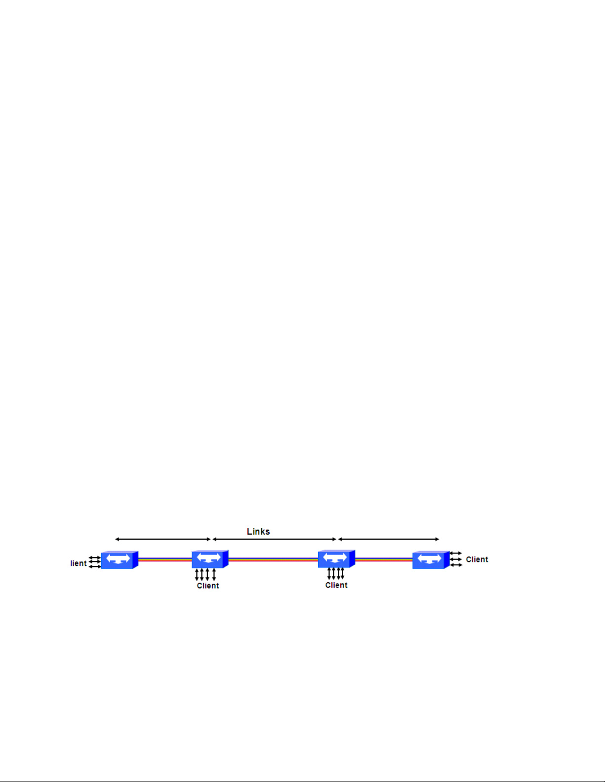
The Infinera Digital Optical Network is shown in Figure 1-1, with ATNs deployed anywhere client access is
desired. The links between the ATNs isolate analog engineering and impairments within that link. Users
can progressively deploy the transport network with ATNs at more points of presence, interconnected by
links, when and where capacity is required, without re-engineering the network.
Figure 1-1 Infinera Digital Optical Network
The Infinera ATN has DWDM and CWDM capabilities and provides support for up to 40 DWDM channels
and 8 CWDM channels. It provides the means for direct access to client data at 10Gbps, 2.7Gbps,
2.5Gbps, 2G, 1G, 1GbE, 622Mbps, 200Mbps or 155Mbps digital granularity at a site, allowing flexible
selection of whether to add/drop, amplify, or optically express individual data streams.
The ATN can be equipped in a variety of network configurations using a common set of circuit packs. The
detailed description of ATN hardware is provided in “Infinera ATN” on page 2-1
ATN Hardware Description Guide Release 1.0
Infinera Proprietary and Confidential
.
Infinera Corporation

Page 3
Infinera Dispersion Management Chassis
The Infinera Dispersion Management Chassis, referred to as the DMC, is an optional chassis which can be
mounted in the same rack as the ATC or the DTC for the purpose of dispersion compensation. A
description of the DMC hardware is provided in “Infinera Dispersion Management Chassis” on page 3-1.
Infinera DTN
The Infinera DTN is a Digital Optical Networking System which provides digital add/drop and bandwidth
management capabilities. The DTN provides digital bandwidth management within a Digital Optical
Network. It provides the means for direct access to client data at 40Gbps, 10Gbps, 2.5Gbps, 1GbE,
622Mbps, and 155Mbps digital granularity at a site, allowing flexible selection of whether to multiplex, add/
drop, amplify, groom, optically express, or switch individual data streams.
For more information on the Infinera DTN, refer to Infinera DTN System Description Guide.
Infinera Optical Line Amplifier
The Infinera Optical Line Amplifier is used to extend the optical reach between DTNs. The Optical Line
Amplifier is deployed at locations where customer access is not anticipated.
For more information on the Optical Line Amplifier hardware, refer to Infinera DTN System Description
Guide.
Note: The Infinera Optical Line Amplifier is used in conjunction with only the Infinera DTN and not
the Infinera ATN.
Infinera Corporation
ATN Hardware Description Guide Release 1.0
Infinera Proprietary and Confidential

Page 4
Page 4
Release 1.0 Feature Summary
Tab le 1- 1 lists the features supported in ATN Release 1.0
Table 1-1 New Features and Hardware for Release 1.0
Feature Description
Network Applications
Network Topologies Point-to-point, linear add/drop multiplexing (ADM), hub-and-spoke, and ring topolo-
gies.
Hardware Modules
Infinera ATN Digital Optical Networking System which provides add/drop capabilities.
ATC-A The ATN Active Transport Chassis (ATC-A) is a 3RU, 11 slot service shelf that can
be mounted in a 19 or 23-inch ANSI or ETSI rack.
The ATC-A includes slots for the following:
• One management module (AMM-A)
• Two Power Conversion Modules (PCMs)
• One Fan tray
• Two EDFA amplifiers (AAMs)
• The ATC-A also has eight flexible slots that can house up to eight Optical Filter
Modules (OFMs) or eight Service Interface Modules (SIMs)
ATC-P The ATN Passive Transport Chassis (ATC-P) is a 2RU, eight slot chassis that can be
mounted in a 19 or 23-inch ANSI or ETSI rack.
The ATC-P includes slots for up to eight Optical Filter Modules (OFMs). The ATC-P
and its modules are not managed by any software interface.
ATN Management Module
(AMM)
ATN Amplifier Modules
(AAM)
Optical Filter Modules
(OFM)
The AMM is the main system controller and performs management and control functions for the ATN. It supports a database branding mechanism that prevents the
installation of an incorrect or outdated control module into a chassis.
AAMs are EDFA based optical amplifier modules. An ATN may be equipped with
AAMs to when optical amplification is required to extend the optical reach between
the ATNs. There are two types of AAMs:
• AAM-B1, which is used as a booster amplifier
• AAM-P1, which is used as a pre-amplifier and in-line amplifier
Performs optical multiplexing and de-multiplexing of Optical Channels to/from SIMs
as well as AAMs. There are several types of DWDM and CWDM OFMs.
• DWDM OFMs— The ATN supports four 10-channel OFMs and ten 4 -channel
OFMs
• CWDM OFMs— The ATN supports four 2-channel OFMs and one 8-channel OFM
ATN Hardware Description Guide Release 1.0
Infinera Proprietary and Confidential
Infinera Corporation

Table 1-1 New Features and Hardware for Release 1.0
Feature Description
Page 5
Service Interface Module
(SIM)
Tributary Optical Module
(TOM)
Dispersion Management
Chassis (DMC)
Dispersion Compensation
Module (DCM)
This module houses the client side and line side tributary optical modules. The Service Interface Module (SIM) maps the client optical signals into electrical signals for
subsequent transmission through the line side tributary optical module.
There are two types of SIMs:
• SIM-T-1-10G is a one port 10G transponder that encapsulates the client signal into
an OTU2/OTU2e frame
• SIM-T-2-2.5GM is a two port 2.5G multi-rate transponder that performs 3R regeneration of the client signal
Tributary Optical Modules (TOMs) are client-side and line-side optical interface modules (field-replaceable). A TOM converts an incoming client optical signal into a
serial electrical signal for further processing in the Service Interface Modules (SIMs).
The TOM also converts out-going signals from electric to optical for line-side transport.
The following TOMs are supported in the ATN:
Line TOMs
• Tributary Optical Module-10G, DWDM XFP (TOM-10G-Dn-LR2)
• Tributary Optical Module-2.5G Multi Rate, DWDM SFP (TOM-MR-Dn-LR2)
• Tributary Optical Module-2.5G Multi Rate, CWDM SFP (TOM-MR-Cn-LR2)
Client TOMs
• Tributary Optical Module-10G-SR0 (TOM-10G-SR0)
• Tributary Optical Module-10G-SR1 (TOM-10G-SR1)
• Tributary Optical Module-2.5G-SR1 (TOM-2.5G-SR1)
• Tributary Optical Module-2.5G-IR2 (TOM-2.5G-IR2)
• Tributary Optical Module-2.5G-SR1 Multi Rate (TOM-2.5GMR-SR1)
• Tributary Optical Module-2.5G-IR1 Multi Rate (TOM-2.5GMR-IR1)
• Tributary Optical Module-1G-LX (TOM-1G-LX)
• Tributary Optical Module-1G-SX (TOM-1G-SX)
OSC TOM
• Tributary Optical Module-100M-C45-L2 (TOM-100M-C45-L2)
The DMC is a passive chassis and does not require management. Depending on the
span characteristics, the DMC is optionally included in ATNs to house Dispersion
Compensation Modules (DCMs).
The Dispersion Compensation Module (DCM) houses the dispersion compensating
fiber that can be optically connected in-line with an AAM. The DCM equalizes chromatic dispersion of different frequency components having different propagation
speeds and reverses the dispersion effect of transmission fiber, to restore the optical
signal.
Infinera Corporation
ATN Hardware Description Guide Release 1.0
Infinera Proprietary and Confidential

Page 6
Page 6
Table 1-1 New Features and Hardware for Release 1.0
Feature Description
System Interfaces
Transport Interfaces The supported client/tributary interfaces are:
• SONET OC-3, OC-12, OC-48 and OC-192 signals
• SDH STM-1, STM-4, STM-16, STM-64 signals
• Fibre Channel 1G (1G FC), Fibre Channel 2G (2G FC) signals
• Ethernet 10GbE LAN Phy, 10GbE WAN Phy, and 1GbE signals
• OTU1 signals
• ESCON and FICON signals
The supported line interfaces are:
• Up to 40 DWDM line-side channels in combination with an Optical Supervisory
Channel (OSC) to provide up to 400Gbps transport and in-band communications
between network elements. The line-side channels include OTU2 (10.7Gbps),
OTU2e (11.1Gbps), 3R output of 2.7Gbps and lower client signals.
• Up to eight CWDM line-side channels in combination with an Optical Supervisory
Channel (OSC) to provide up to 20Gbps transport and in-band communications
between network elements. The line-side channels include 3R output of 2.7Gbps
and lower client signals
Management Connection
Interfaces
Alarm Interfaces The ATC supports five external alarm inputs and ten alarm control outputs. These
Optical Supervisory Channel (OSC)
The AMM includes the following RJ-45 management interfaces:
• Two Nodal Control (NC) ports
• One DCN port (RJ-45 interface)
• One Craft Ethernet port (RJ-45 interface)
• One Craft Serial DCE port (RJ-45 interface)
opto-isolator contacts enable integration with parallel telemetry systems, and provide
office-level alarming.
Of the five external alarm inputs, four can be configured by the user (one is dedicated for ACO). Of the ten external alarm outputs, four can be configured by the user
and the remaining six are based on system alarms (three each for visual and audible).
100M Ethernet Optical Supervisory Channel for inter-node communication.
G.709 Optical Transport
Units (OTU)
ATN Hardware Description Guide Release 1.0
The ATN transports 10G client signals using ITU-T G.709 Optical Transport Units
(OTU2, OTU2E). The ATN supports forty (40) DWDM wavelengths with 100GHz
spacing.
Infinera Proprietary and Confidential
System Architecture
Infinera Corporation

Page 7
Table 1-1 New Features and Hardware for Release 1.0
Feature Description
Hardware Scalability ATN R1.0 can support a total of four ATC-A's in a multi-node configuration. One of
the ATC nodes is connected to the ATN line system using the OSC ports and the
three other ATC nodes are interconnected with the NC 10/100 Ethernet stacking
ports. Remote communications and management to the three stacked ATC nodes is
accomplished using Layer 2 Ethernet communication across the NC ports.
Fault Management
Alarm Surveillance The ATN provides the following alarm surveillance functions:
• Provides detection and user-customized reporting of defects in the ATN. Features
alarm masking and the option to export alarm data.
• The system includes an Alarm Reporting Control (ARC) feature that allows users
to prevent a managed object from reporting alarms during maintenance procedures. The system can be configured to clear or to maintain all pre-existing standing alarms when ARC is enabled.
• Customizable severity levels for Threshold Crossing Alerts (TCAs).
Event Log Provides a wrap-around historical event log that tracks the reports of all changes
that occur within the system. Users can retrieve event log data through the network
management user interfaces.
Maintenance and Troubleshooting
For comprehensive maintenance and troubleshooting, the system supports loopbacks, PRBS generation and detection, and trace messaging.
Equipment Management
Managed Object Model All hardware equipment, physical ports and logical termination points are repre-
sented through the network management interfaces as managed objects, according
to the Telcordia, ITU-T and TMF general information modeling standards. Users can
export inventory information in Tab Separated Value (TSV) and Comma Separated
Value (CSV) format.
State Modeling Implements a standard state model, compliant with TMF814, and GR-1093, for all
the managed objects.
Protection
Digital Subnetwork
Connection Protection
(D-SNCP)
Enables 1+1 protection of diverse circuit paths through the Digital Optical Network
for sub-50ms switching. Digital SNCP increases the overall reliability and service uptime of the optical path, and provides Fault Escalation, which enables Digital SNCP
protection on services that are transported through foreign WDM or SONET/SDH
networks that originate and terminate on Infinera ATNs.
Infinera Corporation
ATN Hardware Description Guide Release 1.0
Infinera Proprietary and Confidential

Page 8
Page 8
Table 1-1 New Features and Hardware for Release 1.0
Feature Description
Performance Monitoring
Optical PM, Digital PM,
SONET/SDH/Ethernet PM
Standards-based Security
Model with Network-wide
User Administration
Security Audit Log The ATN features a persistent circular audit log that records all system configuration
Optical and digital PM data collection is supported on the ATN. SONET/SDH/Ethernet PM data collection is supported in the ATN for the tributary interfaces. Both current and historical PM reset counters are supported, as is automatic notification of
user-defined-threshold crossings for early detection of problems.
The ATN allows the user to customize severity levels for Threshold Crossing Alerts
(TCAs).
Release 1.0 adds support for collection of the following PMs:
• Optical and digital PMs for both the client and line side interfaces of the
SIM-T-1-10G.
• Optical PMs for both the Client and Line side interfaces of the SIM-T-2-2.5GM.
• Optical PMs for the OSC on the AMM
• C-band power monitoring for AAM-B1 line side.
• C-band power monitoring for the AAM-P1 line side.
• Calibration data monitoring for the OFMs
Security and Access Management
Based on the Telcordia GR-815-CORE standard, the security model provides support for user identification, authentication, and access control with user customized
access privileges.
activities and security related events, such as unauthorized attempts and excessive
authentication attempts. The audit log provides traceability of all system-impacting
changes.
Software and Database Management
Software Management Users can remotely download the software image from a user specified FTP server
to the AMM of the ATC-A. Each network element can store three images of the software, which users may selectively activate. The system provides the option to
gracefully "fall-back" or "down-grade" to a prior release in the rare event that a failure
is experienced during the upgrade process. Software images can be managed
across multiple network elements from a centralized location.
Database Management Users can backup, download and restore database versions. Each network element
can store three versions of a database, which users may selectively activate.
Chassis Branding ATC-As contain database versions that are branded - or marked as belonging to a
specific chassis - in order to prevent activation of the wrong or outdated controller
within a given chassis.
Remote Hardware FPGA
Upgrade
ATN Hardware Description Guide Release 1.0
The ATN hardware modules that support the ability to be remotely upgraded include
all types of AAMs and SIMs.
Infinera Corporation
Infinera Proprietary and Confidential

Page 9
Table 1-1 New Features and Hardware for Release 1.0
Feature Description
System Management
ATN SNMP Agent In Release 1.0, IQA NOS ATN provides an embedded SNMPv2c agent on Infinera
network elements in order to meet the management requirements of third party
EMS/NMS systems that are based on the SNMP protocol.
Network Management User Interfaces
Infinera Graphical Node
Manager (GNM) GUI
Infinera Digital Network
Administrator (DNA)
CLI Interface A command line interface (CLI) provides full Fault-management, Configuration,
A web browser-launched Graphical User Interface (GUI) to manage a single network
element. The Infinera GNM provides all of the relevant network element-level Operations, Administration, Maintenance, and Provisioning (OAM&P) functions listed
above in this table.
In DNA Release 5.1, a new feature called Peripheral Nodes is introduced to allow
new node types that are not fully integrated into DNA to be inventoried into the DNA
database. ATN nodes are recognized as peripheral nodes and the following functions are available to the ATN from the DNA.
• The nodes and links between these nodes and/or other Infinera nodes, can be created or deleted in/from DNA, providing DNA users a mechanism to visualize these
nodes and links in the topology map and view them accordingly in inventory managers, namely Link Manager and Node Manager.
• This feature also enables DNA users to start deploying future Infinera network elements (for example, Infinera ATN) before full DNA management integration
becomes available.
• For these Infinera nodes, DNA will provide manual inventory and topology management and also provide a cut-through launch point to the nodal management
interfaces like GNM as supported by these nodes.
Accounting, Performance, and Security (FCAPS) support for ATNs
Infinera Corporation
ATN Hardware Description Guide Release 1.0
Infinera Proprietary and Confidential

Page 10
Page 10
ATN Hardware Description Guide Release 1.0
Infinera Proprietary and Confidential
Infinera Corporation

CHAPTER 2
Infinera ATN
The Infinera ATN, referred to as the ATN, provides digital bandwidth management and client access to the
Coarse Wavelength Division Multiplexing (CWDM) and Dense Wavelength Division Multiplexing (DWDM)
transport bandwidth.
The ATN consists of one or more Access Transport Chassis (ATC), and optionally one or more Dispersion
Management Chassis (DMC) for dispersion compensation. See “Infinera Dispersion Management
Chassis” on page 3-1 for more details on DMC.
This chapter provides a hardware description for the ATN including a functional description of the
hardware, block diagram of the internal signal flow (where applicable), and technical specifications. This
chapter includes the following sections:
“ATC System Specifications” on page 2-2
“ATC Overview” on page 2-5
“ATC Thermal Loading” on page 2-7
“ATC Product Details” on page 2-13
“ATN Management Module (AMM)” on page 2-34
“ATN Amplifier Module (AAM)” on page 2-39
“Optical Filter Modules (OFM)” on page 2-43
“Passive OSC Add/Drop Module” on page 2-76
“Service Interface Module (SIM)” on page 2-79
“Tributary Optical Module (TOM)” on page 2-86
For ATN installation procedures, refer to the Infinera ATN Installation Guide. For ATN turn-up and test
procedures, refer to the Infinera ATN Turn-up and Test Guide.
Refer to Infinera ATN Maintenance and Troubleshooting Guide for a description of module Light Emitting
Diode (LED) status indicators.
Infinera Corporation
Infinera Proprietary and Confidential
ATN Hardware Description Guide Release 1.0

Page 2
ATC System Specifications
This section contains system specifications for the ATC includes the following:
“ATC Power Consumption” on page 2-2
“ATC Compliancy” on page 2-3
“ATC Technical Specifications” on page 2-4
ATC Power Consumption
The power consumption numbers for the ATC are presented as two values:
Typical Power Draw—characterizes average power usage under normal operating system condi-
tions and can be used for estimating average power consumption over time (ongoing operational
cost for power consumption)
Maximum Power Draw—is worst-case power draw under severe equipment, environmental, and
network conditions
Table 2-1 on page 2-2 provides typical and maximum power draw numbers for supported ATC system
components.
Table 2-1 ATC Power Consumption Numbers
Typical Power Draw
Configuration
ATC 1 2 0 360
Fan Tray 34 96
AMM-A 9 12
AAM (B1 and P1 types) 6 7.5
SIM-T-1-10G 13 15
SIM-T-2-2.5GM 6 7
(Watts)
Maximum Power Draw
(Watts)
ATN Hardware Description Guide Release 1.0
Infinera Proprietary and Confidential
Infinera Corporation Infinera Corporation
 Loading...