

Page 1
PN Application Kit User’s Manual 1 Rev. 1.0
www.infineon.com/TLE984x 2017-04-07
TLE9845 Application Kit PN User’s Manual
Product Family: TLE984xQX
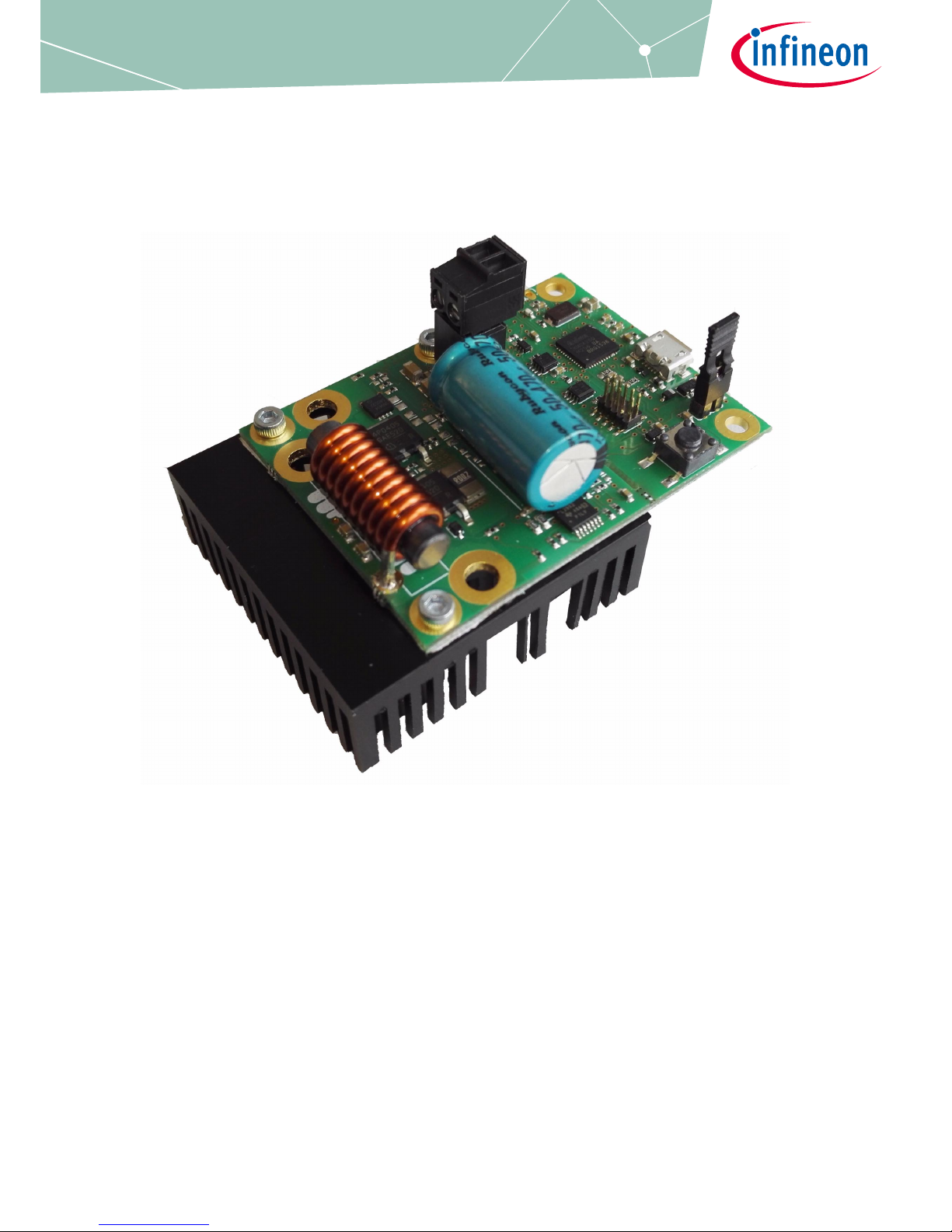
Figure 1 TLE9845QX Application Kit with PN-Halfbridge
About this document
Scope and purpose
The TLE9845_APPKIT_PN is designed to evaluate hardware and software functionalities of the
TLE9845QX in an application similar designed shape.
The p- and n-channel MOSFETs are placed in halfbridge connection to drive DC motors unidirektionally.
This documentation describes the basic use of the TLE9845_APPKIT_PN, a TLE9845 32-bit ARM Cortex M0
Core, its functionality and how to get started with an application running on the evaluation board.
Note: This Evaluationboard is not optimized for EMC behavior.
Intended audience
This Document is for everyone who works with the TLE9845_APPKIT_PN
Page 2

PN Application Kit User’s Manual 2 Rev. 1.0
2017-04-07
TLE9845 Application Kit PN User’s Manual
About this document . . . . . . . . . . . . . . . . . . . . . . . . . . . . . . . . . . . . . . . . . . . . . . . . . . . . . . . . . . . . . . . . . . . . . . 1
Table of Contents . . . . . . . . . . . . . . . . . . . . . . . . . . . . . . . . . . . . . . . . . . . . . . . . . . . . . . . . . . . . . . . . . . . . . . . . . 2
1 Concept . . . . . . . . . . . . . . . . . . . . . . . . . . . . . . . . . . . . . . . . . . . . . . . . . . . . . . . . . . . . . . . . . . . . . . . . . . . . . . . . . 3
2 Interconnections . . . . . . . . . . . . . . . . . . . . . . . . . . . . . . . . . . . . . . . . . . . . . . . . . . . . . . . . . . . . . . . . . . . . . . . . . 4
3 Communication Interfaces . . . . . . . . . . . . . . . . . . . . . . . . . . . . . . . . . . . . . . . . . . . . . . . . . . . . . . . . . . . . . . . . . 5
3.1 LIN and uIO for LIN BSL . . . . . . . . . . . . . . . . . . . . . . . . . . . . . . . . . . . . . . . . . . . . . . . . . . . . . . . . . . . . . . . . . . . . 5
3.2 UART (Virtual COM PORT via USB) . . . . . . . . . . . . . . . . . . . . . . . . . . . . . . . . . . . . . . . . . . . . . . . . . . . . . . . . . . 5
3.3 SWD-Debuginterface (J-Link via USB) . . . . . . . . . . . . . . . . . . . . . . . . . . . . . . . . . . . . . . . . . . . . . . . . . . . . . . . 5
4 Software Toolchain . . . . . . . . . . . . . . . . . . . . . . . . . . . . . . . . . . . . . . . . . . . . . . . . . . . . . . . . . . . . . . . . . . . . . . . 6
4.1 Keil µVision 5 . . . . . . . . . . . . . . . . . . . . . . . . . . . . . . . . . . . . . . . . . . . . . . . . . . . . . . . . . . . . . . . . . . . . . . . . . . . . . 6
4.2 Infineon Config Wizard . . . . . . . . . . . . . . . . . . . . . . . . . . . . . . . . . . . . . . . . . . . . . . . . . . . . . . . . . . . . . . . . . . . . 6
4.3 TLE9845QX Installation . . . . . . . . . . . . . . . . . . . . . . . . . . . . . . . . . . . . . . . . . . . . . . . . . . . . . . . . . . . . . . . . . . . . 6
4.4 Debug Connection Setup . . . . . . . . . . . . . . . . . . . . . . . . . . . . . . . . . . . . . . . . . . . . . . . . . . . . . . . . . . . . . . . . . . 6
4.5 GUI Description . . . . . . . . . . . . . . . . . . . . . . . . . . . . . . . . . . . . . . . . . . . . . . . . . . . . . . . . . . . . . . . . . . . . . . . . . . . 7
4.5.1 General . . . . . . . . . . . . . . . . . . . . . . . . . . . . . . . . . . . . . . . . . . . . . . . . . . . . . . . . . . . . . . . . . . . . . . . . . . . . . . . . 7
4.5.2 Open the GUI . . . . . . . . . . . . . . . . . . . . . . . . . . . . . . . . . . . . . . . . . . . . . . . . . . . . . . . . . . . . . . . . . . . . . . . . . . . 7
4.5.3 Connecting to the TLE9845 Device . . . . . . . . . . . . . . . . . . . . . . . . . . . . . . . . . . . . . . . . . . . . . . . . . . . . . . . . 8
5 Schematic and Layout . . . . . . . . . . . . . . . . . . . . . . . . . . . . . . . . . . . . . . . . . . . . . . . . . . . . . . . . . . . . . . . . . . . . . 9
6 Revision History . . . . . . . . . . . . . . . . . . . . . . . . . . . . . . . . . . . . . . . . . . . . . . . . . . . . . . . . . . . . . . . . . . . . . . . . . 12
Table of Contents
Page 3
PN Application Kit User’s Manual 3 Rev. 1.0
2017-04-07
TLE9845 Application Kit PN User’s Manual
Concept
1 Concept
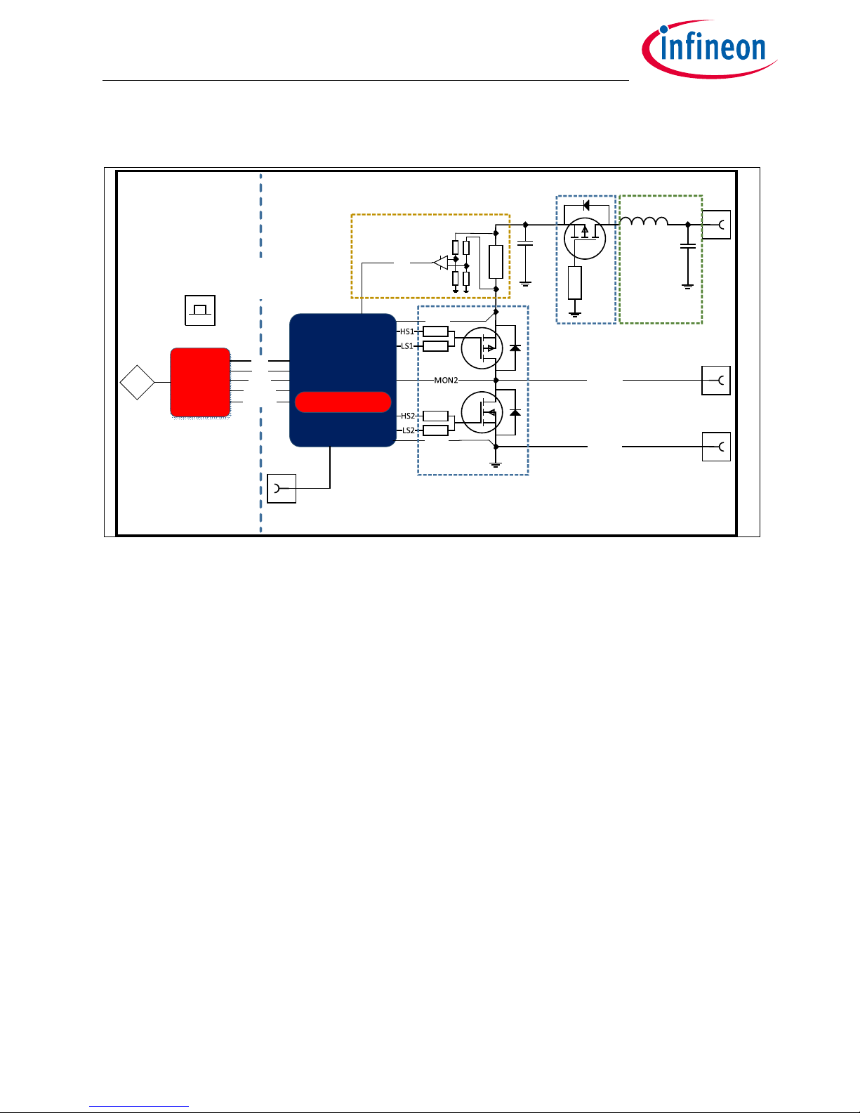
Figure 2 PN Applikation Kit Concept
The TLE9845_App_Kit_PN provides an application near circuit to evaluate unidirectional DC motors. The
active PN-halfbridge can be used to evaluate motor connected to GND applications.
The TLE9845QX device is placed underneath the DC-link capacitor. The board is protected against reverse
polarity of input voltage supply.
A PN-channel MOSFET halfbridge is connected to the integrated highside and lowside switches of the
TLE9845QX Device.
In addition a highside current sense resistor is placed with an external operational amplifier.
It is connected to the ADC1 (P2.3).
The Application Kit provides a breakable On-Board debugger. It provides a SWD-Debug connection and a
virtual COM port for serial UART communication.
Power supply and motor connectors are accessable via plated through hole contacts, which can be used to
place M2.5 pressnuts (optionally).
Board features:
• Application near circuit (Motor connected to GND)
• Overcurrent Protection (external highside Shunt)
• Drain-Source-Monitoring (Differential Unit)
• USB-Communication and Debug-Interface (USB-Connector)
• Demo-Application Code and Graphical User Interface (GUI)
•LIN-PWM Example Code (PWM Genrator with GUI)
MON4
MON1
TLE9845QX
Break Edge
Onboard
Debug
USB
ARM Cortex M0
M+
MOTOR -
MOTOR +
M-
VBAT
TMS
P0.0
RESET
P1.0 TXD
P1.1 RXD
LIN/
PWM
D
RESET Button
Breakable
Debug Board
TLE9845QX Application Board
with LIN/PWM connection
P2.3
Reverse Polarity
Protection
High Side Current Measurement
with external Opamp
PN-Half Bridge
Input Filter
Page 4
PN Application Kit User’s Manual 4 Rev. 1.0
2017-04-07
TLE9845 Application Kit PN User’s Manual
Interconnections
2 Interconnections
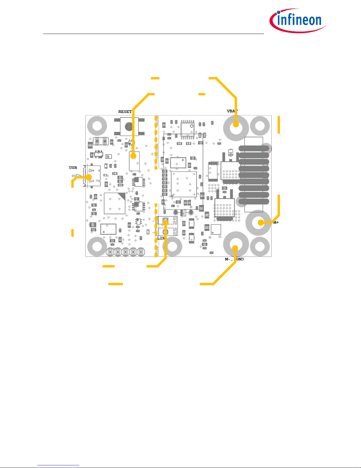
Figure 3 Interconnections Overview
2.5mm Screw Nut Connectors
Ground, voltagesupply (operating Voltage is documented in the datasheet) can be connected via 2.5mm
Screw Nuts.
Motor contacts can also be accessed with 2.5mm screws. MOTOR(+) has a seperate connector. MOTOR(-) is
shared with the GND connector.
LIN/PWM Connector
This connector is a direct access to the LIN/PWM Interface of the TLE9845QX. After Breaking the Debug-
Interface. BSL-Mode can be used to perform programm updates via LIN Interface Chapter 3.
USB
An Onboard-debugger is implemented on the TLE9845QX Appkit. The USB-Connection provides a Debug- and
Serial-interface to the PC. More information in Chapter 3.3.
SWD Interface
The SWD PIN-Header can be used optionally, instead of using the On-Board Debug Interface.
Batterie Voltage
Connector
SWD Interface
USB Interface
LIN/PWM
Connector
Motor(-), GND Connector
Motor(+) Connector
Brake Edge
Page 5
PN Application Kit User’s Manual 5 Rev. 1.0
2017-04-07
TLE9845 Application Kit PN User’s Manual
Communication Interfaces
3 Communication Interfaces
3.1 LIN and uIO for LIN BSL
The device integrated LIN transceiver is connected to a dedicated Connector (see Figure 3). To integrate the
device in a LIN network it is sufficient to use the single wire banana interface. The BSL interface is intended to
program the device via LIN. For further information about the uIO interface see www.hitex.com/uio.
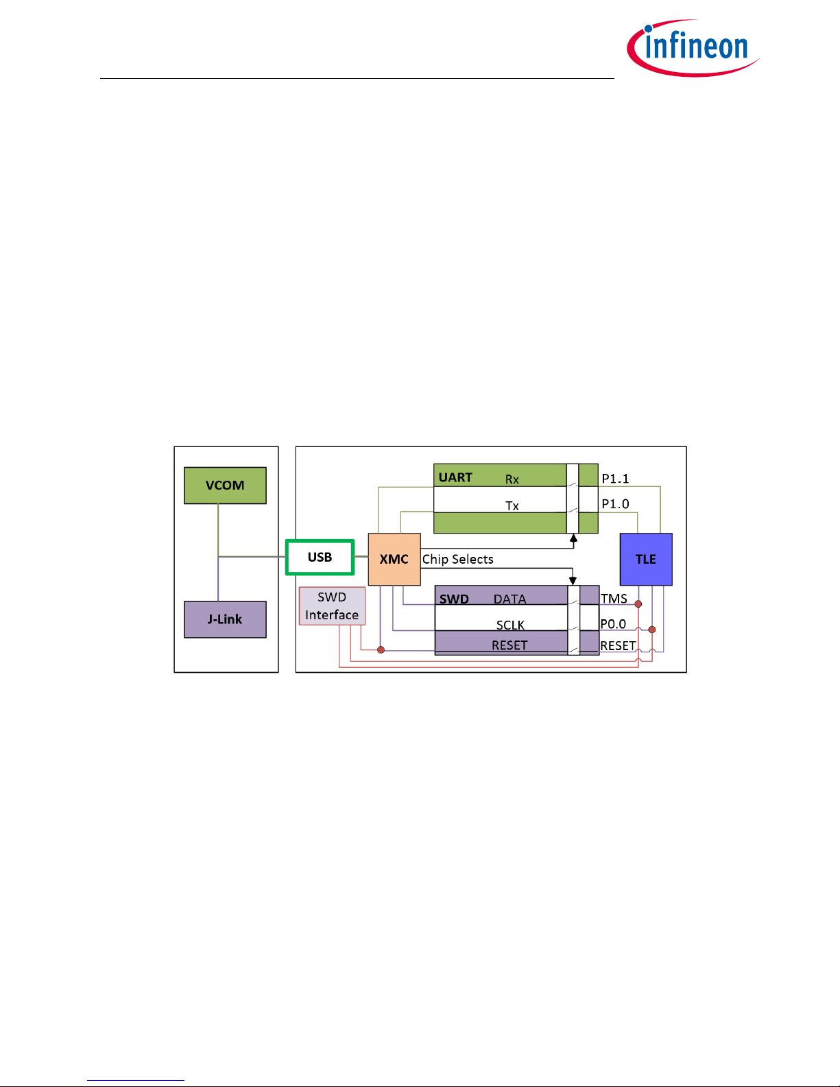
3.2 UART (Virtual COM PORT via USB)
A virtual COM port provided by Segger driver enables a PC – board – communication via UART. The UART2
module of TLE9845QX uses the pins P1.0 (transmit) and P1.1 (receive). Those are connected to the XMC4200,
which emulates Rx and Tx on PC side with Segger firmware. Though they can be disconnected physically,
bidirectional level shifters ensure that the XMC pins are hi-Z in case the virtual COM port is not used. By
connecting the evaluation board to the PC a virtual COM port gets emulated by the Segger driver
automatically. The virtual COM port will show up in the Microsoft® Windows® device manager.
Figure 4 UART and Debugging
Note: Only one of the interfaces USB or SWD can be used at one time. While using the SWD interface the XMC is
ho ld i n re set. As l ong as a d ebu gge r is c onn ect ed wi th the SWD interface it eliminates therefore debugging
or UART via USB.
3.3 SWD-Debuginterface (J-Link via USB)
For serial wire debug the TLE984x uses the pins TMS (data) and P0.0 (clock). Level shifters between XMC4200
and TLE9845QX allow using P0.0, while it is not used for debugging.
The Segger J-Link module on board allows serial wire debugging via USB. Alternative debugging via SWD
interface is possible to debug with another ISP than the onboard Segger e.g. U-Link2. Therefore the signals are
routed through the 10 pin header SWD interface between the XMC4200 and the TLE984x. The pin configuration
makes sure that the XMC is hold in reset while another debugger is physically connected to X11. The virtual
COM port will be disabled, while the external ISP is connected.
Page 6
PN Application Kit User’s Manual 6 Rev. 1.0
2017-04-07
TLE9845 Application Kit PN User’s Manual
Software Toolchain
4 Software Toolchain
4.1 Keil µVision 5
The recommended Integrated Software Developement Environment is Keil® µVision5®. Infineons embedded
Power family is suported. For more information about the Toolchain go to: www.keil.com
4.2 Infineon Config Wizard
In addition to the IDE, Infineon® provides the ConfigWizard. The tool is designed for code configuration, in
combination with the IDE. Infineons Config Wizard can be downloaded via:
www.infineon.com/embeddedpower
4.3 TLE9845QX Installation
All embedded Power products can be installed to Keil® µVision5® via “Pack Installer”. Browsing to the Infineon
chapter in “All Devices” will lead to the “TLE98xx Series”. The “.pack” file comes with several code examples,
to provide an easy start up and speed up software developement.
4.4 Debug Connection Setup
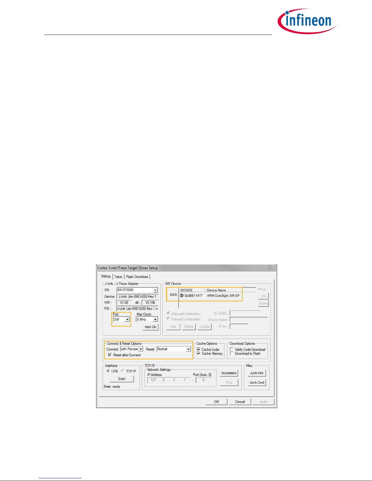
For a proper Flash and Debug Connection, Install V5.10 (or newer) from: www.segger.com/jlink-software.html
Keil® µVision5® has to be configured in the IDE Menu “Options for Target”. After connecting the USB-cable and
power up the Evalboard, go to the “Debug” register-card and choose “J-LINK / J-TRACE Cortex” and press
”Settings”.
Figure 5 Debug and Flash Configuration
If the board has been connected successfully, the ARM IDCODE will be visible in the SW Device Window.
If connection fails, “Connect & Reset Options” and “Port” window has to be checked.
Page 7
PN Application Kit User’s Manual 7 Rev. 1.0
2017-04-07
TLE9845 Application Kit PN User’s Manual
Software Toolchain
4.5 GUI Description
4.5.1 General
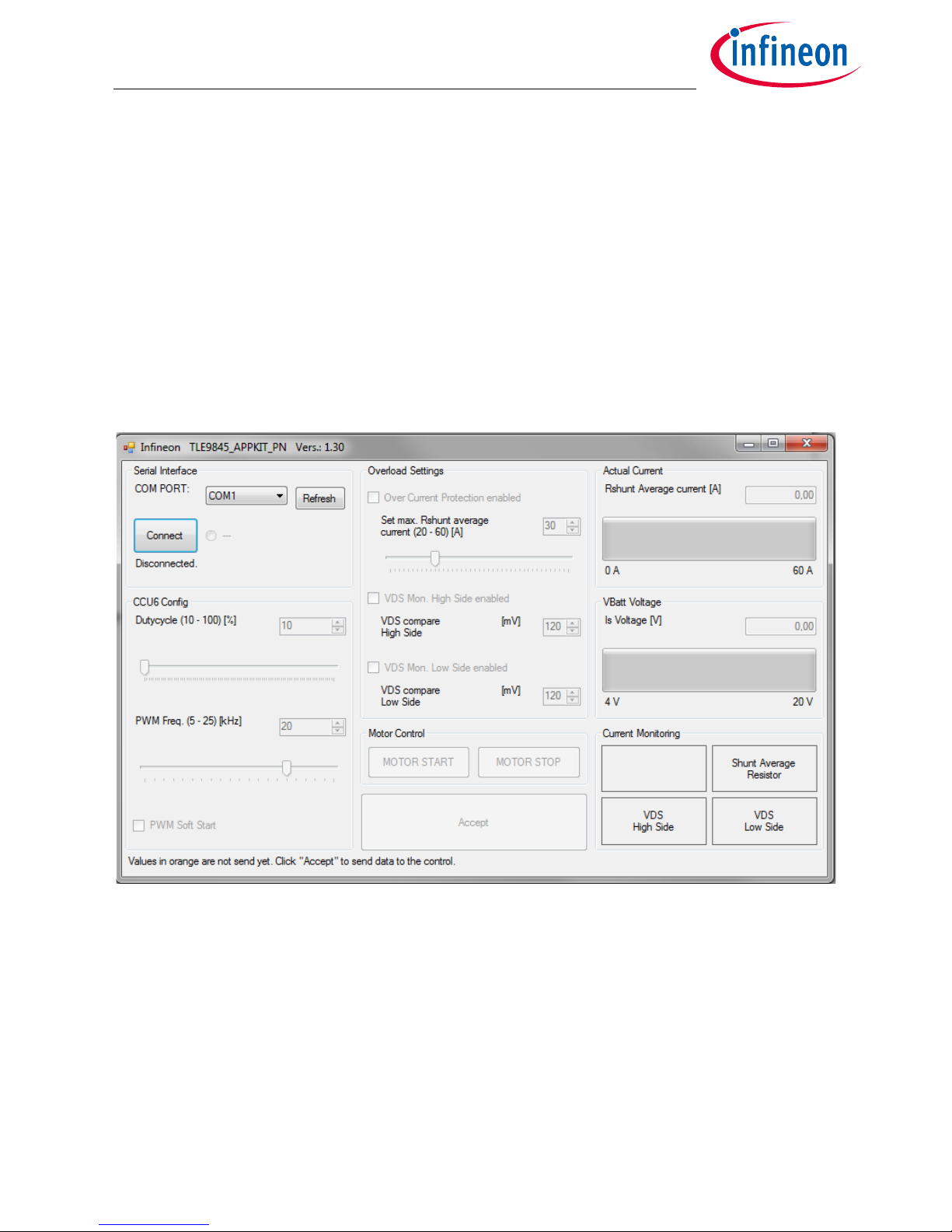
The GUI (General User Interface) is a comfortable tool to control the functionality of the TLE9845 device over
an USB interface.
The GUI-software was written in the programming language C# with MS Visual Studio 2015. The software will
run under Windows 7, Windows 8 and Windows 10.
4.5.2 Open the GUI
The graphical user interface is shown in Figure 6. It can be downloaded at www.infineon.com/TLE984x.
Figure 6 WindowsApplication_PN_130 GUI: Unconnected
Page 8
PN Application Kit User’s Manual 8 Rev. 1.0
2017-04-07
TLE9845 Application Kit PN User’s Manual
Software Toolchain
4.5.3 Connecting to the TLE9845 Device
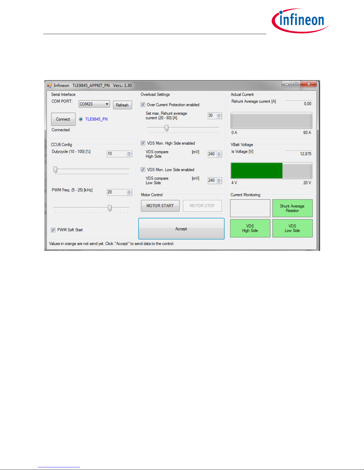
Click on Refresh and select the COM PORT. Press Connect:
Figure 7 WindowsApplication_PN_130 GUI: Connected
The PN_Appkit is now connected and can be controlled. The GUI gives analog information over the average
current, measured at the Shunt resistor and the Supply Voltage.
Page 9
PN Application Kit User’s Manual 9 Rev. 1.0
2017-04-07
TLE9845 Application Kit PN User’s Manual
Schematic and Layout
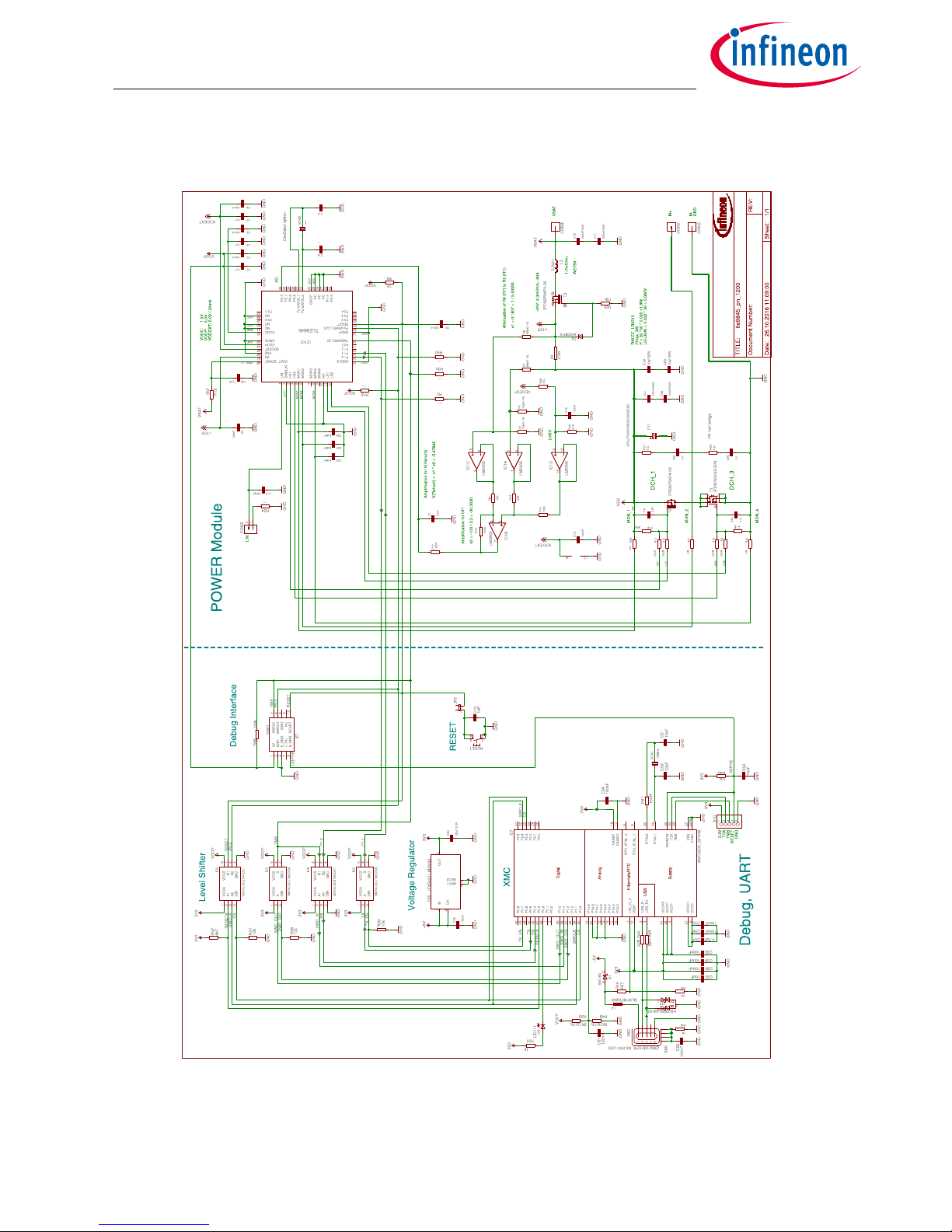
5 Schematic and Layout
Figure 8 schematic sheet: TLE9845QX with PN-MOSFET halfbridge and On Board Debug Interface
Note: This is a very simplified example of an application circuit and bill of material. The function must be
verified in the application.
Page 10
PN Application Kit User’s Manual 10 Rev. 1.0
2017-04-07
TLE9845 Application Kit PN User’s Manual
Schematic and Layout
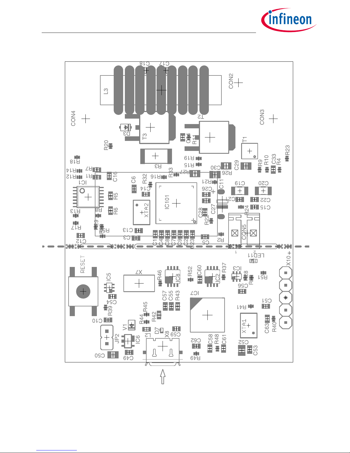
Figure 9 Parts placement
Note: This is a very simplified example of an application circuit and bill of material. The function must be
verified in the application.
Page 11
PN Application Kit User’s Manual 11 Rev. 1.0
2017-04-07
TLE9845 Application Kit PN User’s Manual
Schematic and Layout
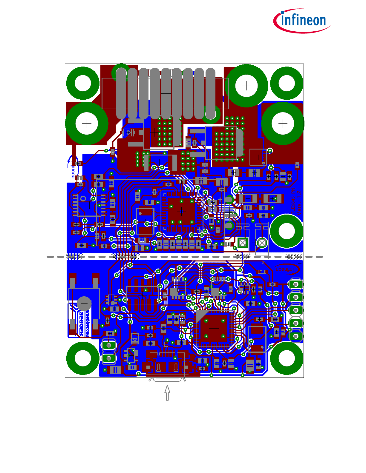
Figure 10 Layout
Note: This is a very simplified example of an application circuit and bill of material. The function must be
verified in the application.
Page 12

PN Application Kit User’s Manual 12 Rev. 1.0
2017-04-07
TLE9845 Application Kit PN User’s Manual
Revision History
6 Revision History
Revision Date Changes
1.0 2017-04-07 Release State
Page 13

Trademarks of Infineon Technologies AG
µHVIC™, µIPM™, µPFC™, AU-ConvertIR™, AURIX™, C166™, CanPAK™, CIPOS™, CIPURSE™, CoolDP™, CoolGaN™, COOLiR™, CoolMOS™, CoolSET™, CoolSiC™,
DAVE™, DI-POL™, DirectFET™, DrBlade™, EasyPIM™, EconoBRIDGE™, EconoDUAL™, EconoPACK™, EconoPIM™, EiceDRIVER™, eupec™, FCOS™, GaNpowIR™,
HEXFET™, HITFET™, HybridPACK™, iMOTION™, IRAM™, ISOFACE™, IsoPACK™, LEDrivIR™, LITIX™, MIPAQ™, ModSTACK™, my-d™, NovalithIC™, OPTIGA™,
OptiMOS™, ORIGA™, PowIRaudio™, PowIRStage™, PrimePACK™, PrimeSTACK™, PROFET™, PRO-SIL™, RASIC™, REAL3™, SmartLEWIS™, SOLID FLASH™,
SPOC™, StrongIRFET™, SupIRBuck™, TEMPFET™, TRENCHSTOP™, TriCore™, UHVIC™, XHP™, XMC™.
Trademarks updated November 2015
Other Trademarks
All referenced product or service names and trademarks are the property of their respective owners.
Edition 2017-04-07
Published by
Infineon Technologies AG
81726 Munich, Germany
© 2017 Infineon Technologies AG.
All Rights Reserved.
Do you have a question about any
aspect of this document?
Email: [email protected]
Document reference
IMPORTANT NOTICE
The information contained in this application note is
given as a hint for the implementation of the product
only and shall in no event be regarded as a description
or warranty of a certain functionality, condition or
quality of the product. Before implementation of the
product, the recipient of this application note must
verify any function and other technical information
given herein in the real application. Infineon
Technologies hereby disclaims any and all warranties
and liabilities of any kind (including without limitation
warranties of non-infringement of intellectual
property rights of any third party) with respect to any
and all information given in this application note.
The data contained in this document is exclusively
intended for technically trained staff. It is the
responsibility of customer’s technical departments to
evaluate the suitability of the product for the intended
application and the completeness of the product
information given in this document with respect to
such application.
For further information on technology, delivery terms
and conditions and prices, please contact the nearest
Infineon Technologies Office (www.infineon.com).
WARNINGS
Due to technical requirements products may contain
dangerous substances. For information on the types
in question please contact your nearest Infineon
Technologies office.
Except as otherwise explicitly approved by Infineon
Technologies in a written document signed by
authorized representatives of Infineon Technologies,
Infineon Technologies’ products may not be used in
any applications where a failure of the product or any
consequences of the use thereof can reasonably be
expected to result in personal injury.
Please read the Important Notice and Warnings at the end of this document
Page 14

Mouser Electronics
Authorized Distributor
Click to View Pricing, Inventory, Delivery & Lifecycle Information:
Infineon:
TLE9845APPKITPNTOBO1
 Loading...