

Page 1

Getting Started -
XMC™ LED Current
Control Explorer Kit
XMC Microcontrollers
Apr 2016
Page 2
Agenda
Kit Overview
Hardware Overview
Tooling Overview
Getting Started
Resource Listing
Support Material
1
2
3
4
5
6
2
Copyright © Infineon Technologies AG 2016. All rights reserved.
Page 3
Agenda
Kit Overview
Hardware Overview
Tooling Overview
Getting Started
Resource Listing
Support Material
1
2
3
4
5
6
3
Copyright © Infineon Technologies AG 2016. All rights reserved.
Page 4
Kit Overview (1/7)
Easy entry into smart LED lighting with XMC™ MCUs
› Low cost, flicker-free, smart and connected single channel LED driver concept
demonstrator
› 15W Single Channel CCM DC/DC Buck converter in peak-current control mode
› Software-based automatic adaptation to different input DC voltages and LED
forward voltages
› Isolated DALI Interface card
– DALI Software Stack available
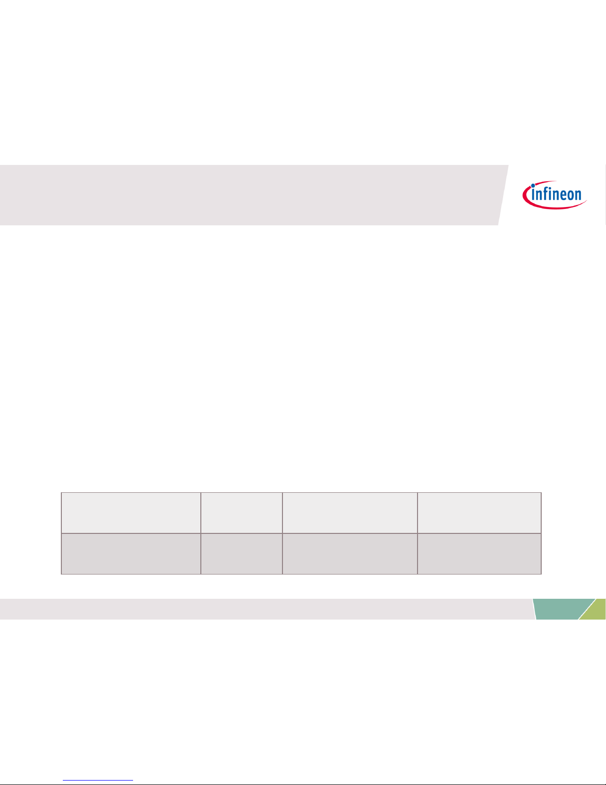
Recommended LED System Overview
4
Copyright © Infineon Technologies AG 2016. All rights reserved.
MAX DC Supply
V
IN
(Max)
I
LED
Peak I
AVERAGE
V
FORWARD
LED
30V 1A <800mA
≤V
IN
Page 5
Kit Overview (2/7)
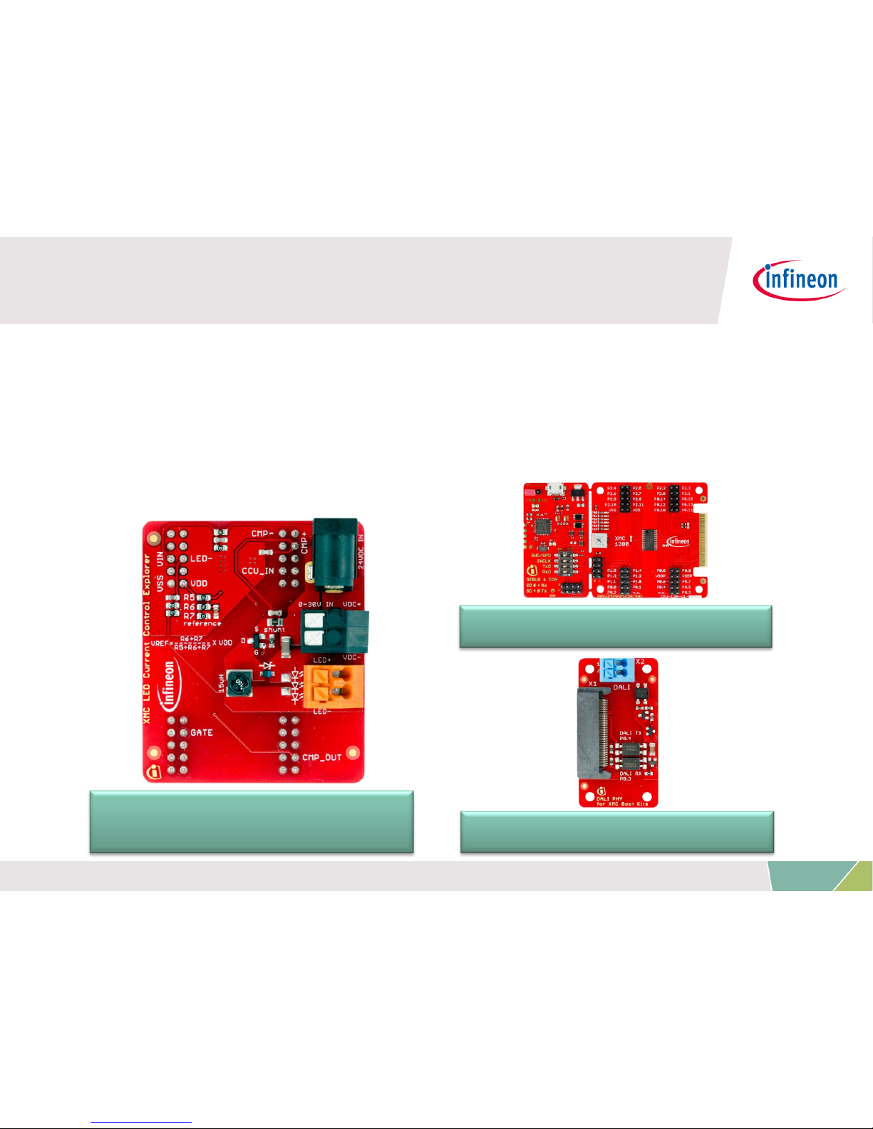
› XMC™ LED Current Control Explorer Kit
– XMC™ LED Current Control Explorer Card
– XMC1300 Boot Kit (XMC1302-AB)
– DALI PHY for XMC™ Boot Kits
XMC1300 Boot Kit
XMC™ LED Current Control
Explorer Card
DALI PHY for XMC™ Boot Kits
5
Copyright © Infineon Technologies AG 2016. All rights reserved.
Page 6

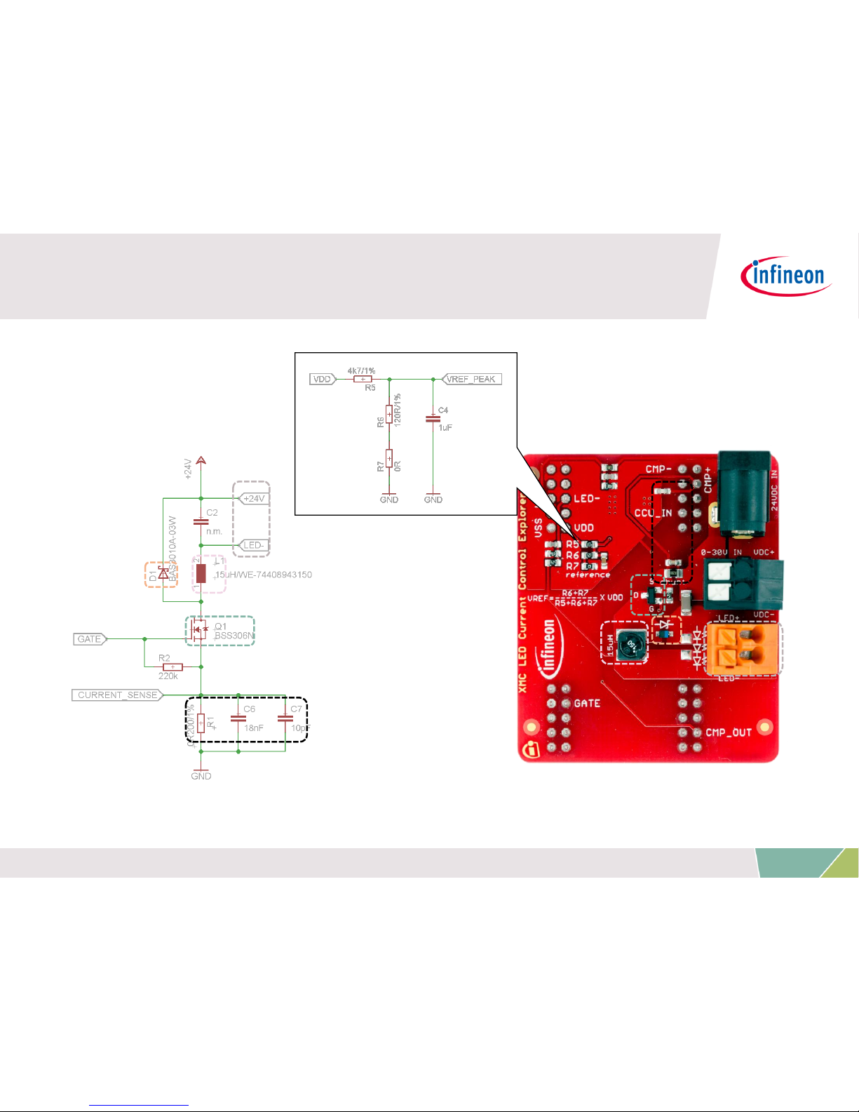
› XMC™ LED Current Control Explorer Card
Kit Overview (3/7)
Voltage Divider for
Comparator Reference
24V DC
Input Jack
0-30V DC
Input Jack
Output jack
to LED engine
Header
Connectors
6
Copyright © Infineon Technologies AG 2016. All rights reserved.
BAS3010A-03W
(Schottky Diode)
BSS306N (OptiMOS™)
Page 7
Kit Overview (4/7)
7
Copyright © Infineon Technologies AG 2016. All rights reserved.
Page 8
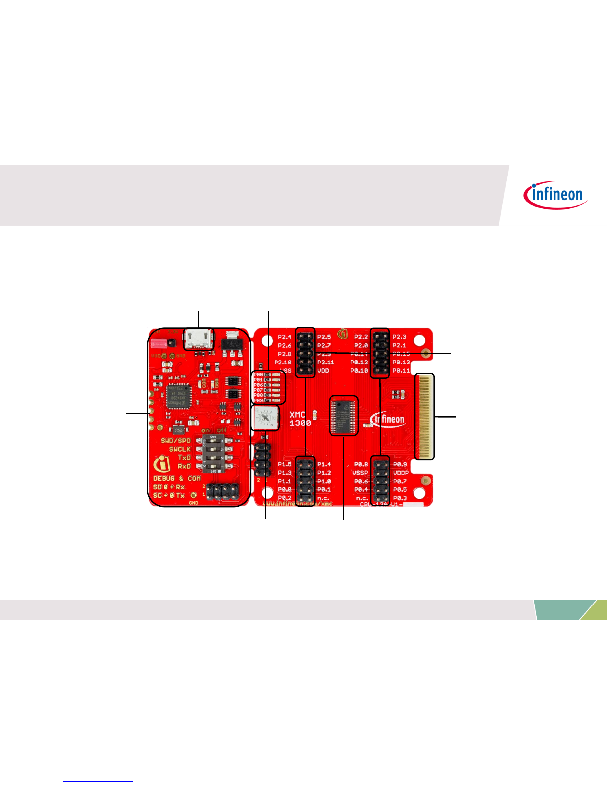
› XMC1300 Boot Kit
Kit Overview (5/7)
On-board COM
and Segger
J-Link debugger
XMC1302-AB
Pin headers
Micro USB
Status Indicator LEDs
Potentiometer
Edge
Connector
8
Copyright © Infineon Technologies AG 2016. All rights reserved.
Page 9

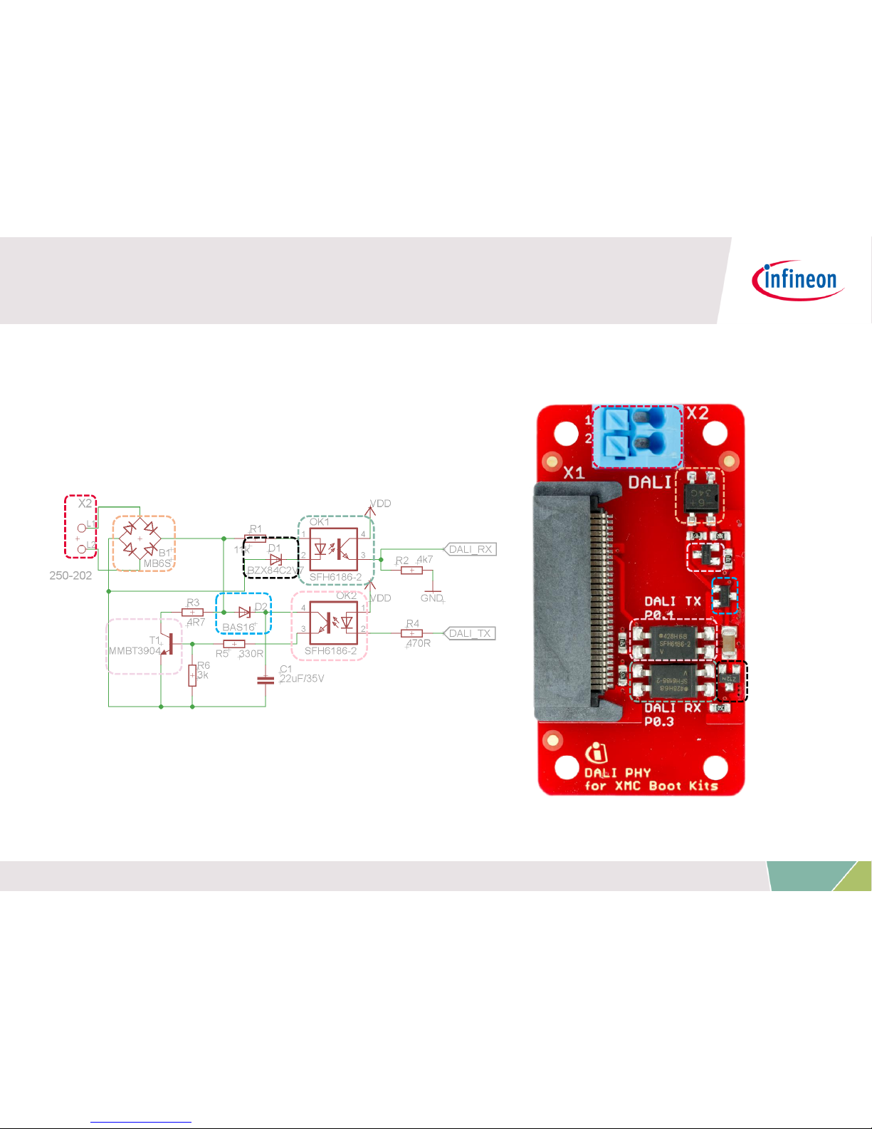
› DALI PHY for XMC™ Boot Kits
Kit Overview (6/7)
SAMTEC
Connector to
Boot Kit
WAGO Connector
to DALI Bus
Isolated DALI
Interface
Circuit
9
Copyright © Infineon Technologies AG 2016. All rights reserved.
Page 10
Kit Overview (7/7)
10
Copyright © Infineon Technologies AG 2016. All rights reserved.
Page 11
Agenda
Kit Overview
Hardware Overview
Tooling Overview
Getting Started
Resource Listing
Support Material
1
2
3
4
5
6
11
Copyright © Infineon Technologies AG 2016. All rights reserved.
Page 12
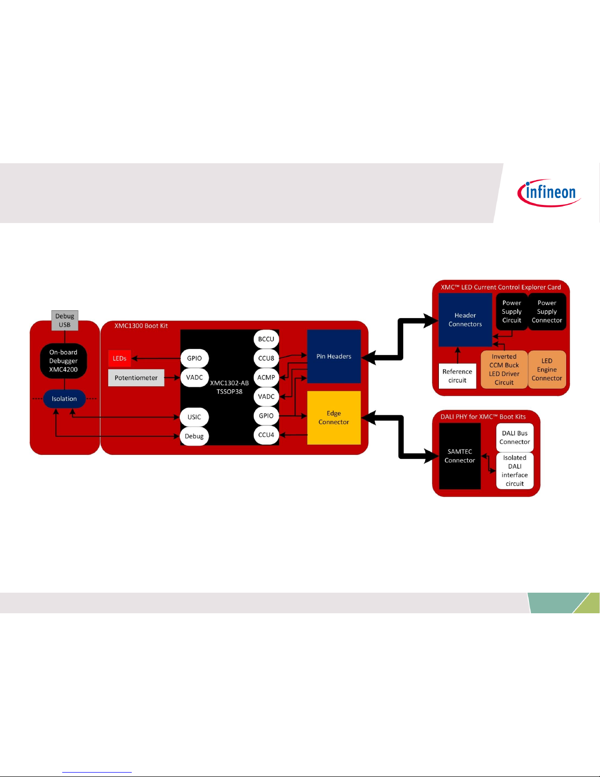
› Hardware block diagram of kit
Hardware Overview (1/2)
12
Copyright © Infineon Technologies AG 2016. All rights reserved.
Page 13
Hardware Overview (2/2)
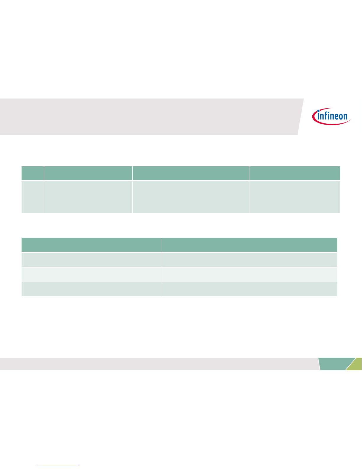
› Kit information
› Infineon parts utilized on Kit Nr. 1:
Infineon Parts
Order Number
XMC1302
Microcontroller
XMC1302T038X0200ABXUMA1
Schottky
Diode BAS3010A-03W
BAS3010A03WE6327HTSA1
Transistor BSS306N
BSS306NH6327XTSA1
Nr.
Kit
Name
Kit Description
Order Number
1
KIT_XMC1_LED_CC
_EXP_001
XMC™ LED Current
Control Explorer Kit
KIT_XMC1_LED_CC
_EXP_001
13
Copyright © Infineon Technologies AG 2016. All rights reserved.
Page 14

Agenda
Kit Overview
Hardware Overview
Tooling Overview
Getting Started
Resource Listing
Support Material
1
2
3
4
5
6
14
Copyright © Infineon Technologies AG 2016. All rights reserved.
Page 15
Tooling Overview –
DAVE™ (1/5)
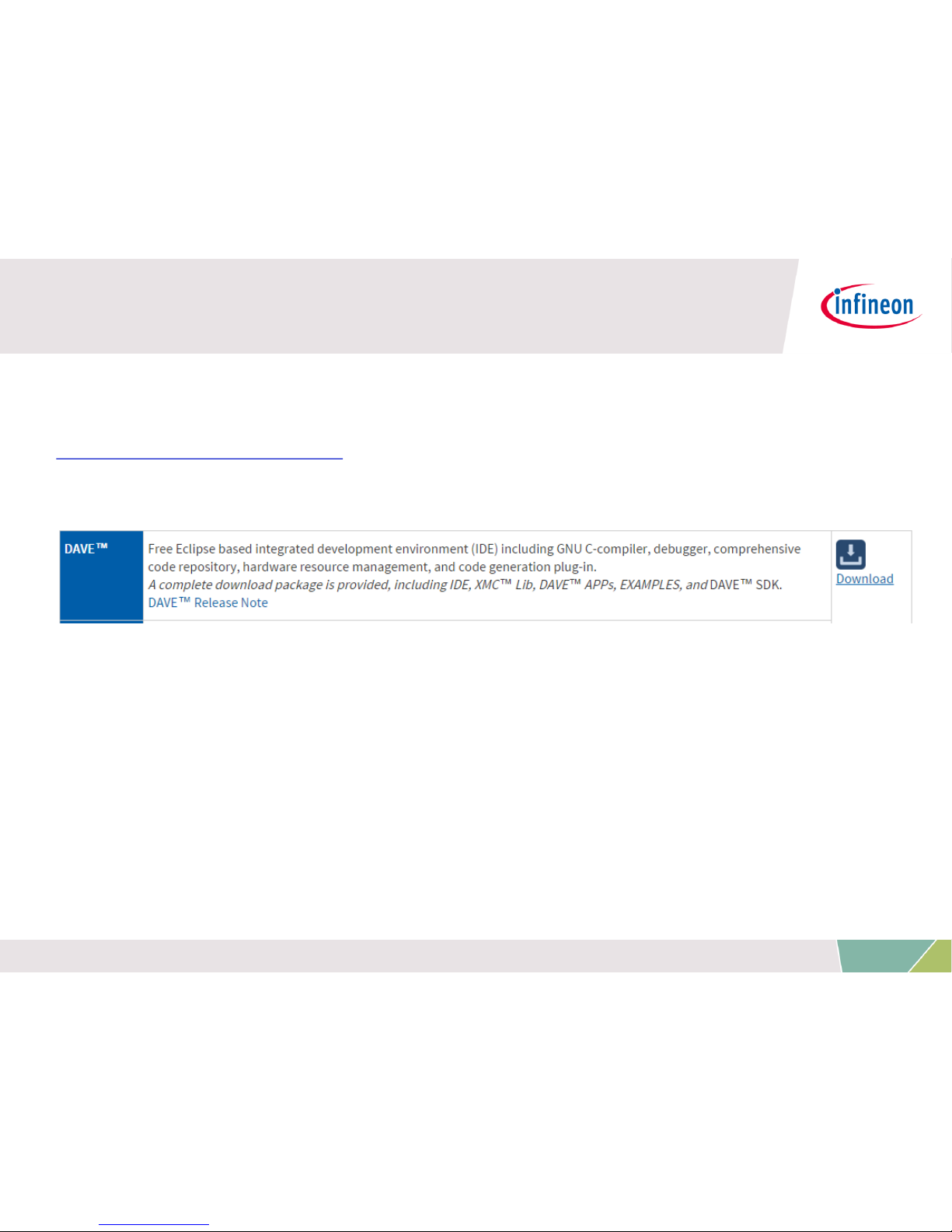
› Download DAVE™ installer package from:
http://www.infineon.com/dave
› Download and unzip the installer package
› Run *_Setup.exe file to install DAVE™ and Segger J-Link drivers
› After Installation, DAVE™ v4 can be started from desktop.
15
Copyright © Infineon Technologies AG 2016. All rights reserved.
Page 16

Tooling Overview –
DAVE™ (2/5)
› Check for DAVE™ updates
Help Check for Updates
16
Copyright © Infineon Technologies AG 2016. All rights reserved.
Page 17

Tooling Overview –
DAVE™ (3/5)
› Install DAVE™ APPs and Device Descriptions
Help Install DAVE™ APP/Example/Device Library
› Note: You may skip the above step if you are not using DAVE™
APPs
17
Copyright © Infineon Technologies AG 2016. All rights reserved.
Page 18

Tooling Overview –
DAVE™ (4/5)
› Select DAVE™ APPs Library Manager in the drop-down menu
› Select Library_DAVEApps and Library_DAVEDeviceDescriptions
(for XMC1300 Device) and click Next
18
Copyright © Infineon Technologies AG 2016. All rights reserved.
Page 19

Tooling Overview –
DAVE™ (5/5)
› Accept terms of the license agreements and click Finish
› DAVE™ APPs and DAVE™ device descriptions are installed
19
Copyright © Infineon Technologies AG 2016. All rights reserved.
Page 20

Agenda
Kit Overview
Hardware Overview
Tooling Overview
Getting Started
Resource Listing
Support Material
1
2
3
4
5
6
20
Copyright © Infineon Technologies AG 2016. All rights reserved.
Page 21

Getting Started
Setting up the Kit (1/4)
1. Plug the XMC™ LED Current Control Explorer Card onto the
XMC1300 Boot Kit
21
Copyright © Infineon Technologies AG 2016. All rights reserved.
Page 22

Getting Started
Setting up the Kit (2/4)
2. Connect the DALI PHY for XMC™ Boot Kits card to the
XMC1300 Boot Kit
22
Copyright © Infineon Technologies AG 2016. All rights reserved.
Page 23

Getting Started
Setting up the Kit (3/4)
3. Connect the LED light engine to the XMC™ LED Current Control
Explorer card via the orange connectors
23
Copyright © Infineon Technologies AG 2016. All rights reserved.
Page 24

Getting Started
Setting up the Kit (4/4)
4. Connect the kit to PC and power supply
From PC
24V DC Adapter
OR
0-30V DC Power
DBG LED turns
ON
24
Copyright © Infineon Technologies AG 2016. All rights reserved.
Page 25

Getting Started
Adjusting LED Brightness (1/3)
› Option 1: Via potentiometer with a screwdriver
25
Copyright © Infineon Technologies AG 2016. All rights reserved.
Voltage is read by ADC, and then
SW changes density of the
modulation signal
Page 26

Getting Started
Adjusting LED Brightness (2/3)
› Option 2: Via DALI communication
Connect to powered DALI
Bus and start sending
commands from DALI
master
26
Copyright © Infineon Technologies AG 2016. All rights reserved.
Page 27

Getting Started
Adjusting LED Brightness (3/3)
› DALI commands supported based on 62386-102:2009
– Direct arc power command
– Indirect arc power control commands e.g. OFF, UP, DOWN etc.
– Query commands e.g. QUERY STATUS, QUERY ACTUAL LEVEL
etc.
– Special commands e.g. INITIALISE, RANDOMISE etc.
27
Copyright © Infineon Technologies AG 2016. All rights reserved.
Page 28

Getting Started
Downloading the Kit Software (1/3)
› http://www.infineon.com/xmc-led-ccexp
› Click on the ‘Software & Tools’ tab
› Download the example project(s)
28
Copyright © Infineon Technologies AG 2016. All rights reserved.
Page 29

Getting Started
Downloading the Kit Software (2/3)
› List of available projects
1. Basic-level: Introduction to possible implementations of
control loop for CCM Buck, with dimming via potentiometer
XMCLib-based
• LED_CCEXP_A1_BCCU_ACMP_ERU_CCU4
• LED_CCEXP_A2_BCCU_ACMP_EXT_CCU4
• LED_CCEXP_A3_ACMP_BCCU_CCU8
APP-based
• LED_CCEXP_B1_BCCU_ACMP_ERU_CCU4
• LED_CCEXP_B2_BCCU_ACMP_EXT_CCU4
• LED_CCEXP_B3_ACMP_BCCU_CCU8
29
Copyright © Infineon Technologies AG 2016. All rights reserved.
Page 30

Getting Started
Downloading the Kit Software (3/3)
› List of available projects (continued)
2. Application-level: Fastest control loop for CCM Buck
implementation with dimming via potentiometer or DALI
APP-based
• LED_CCEXP_C1_ACMP_BCCU_CCU8_DALICG (will be available soon)
• LED_CCEXP_C2_AUTOMATIC_RIPPLE_TUNING: with automatic current
ripple tuning according to input voltage and LED load to maintain LED
average current (Default pre-loaded code)
3. Customization: Basic project without dimming, for user to
adopt kit to their own LED engine (more instructions from
here)
APP-based
• LED_CCEXP_D1_MANUAL_CALIB
30
Copyright © Infineon Technologies AG 2016. All rights reserved.
Page 31

1. Open DAVE™
2. In DAVE™ workspace, import the
downloaded project:
– File Import Infineon
DAVE Project
– Click Next
– Check “Select Archive File”
– Browse to the downloaded
project zip file
– Click Open
Project name will appear under
Project List
– Click Finish
Getting Started
Programming the kit (1/3)
31
Copyright © Infineon Technologies AG 2016. All rights reserved.
Page 32

Getting Started
Programming the kit (2/3)
› Build project
1. Click
2. Wait for Build to finish
› Download code
1. Ensure that the power to the XMC™ LED Current Control
Explorer card is turned OFF
2. Click
3. Switch to TASKING Debug view
4. Click to run code
› Turn ON the power to the XMC™ LED Current Control Explorer
card
› Adjust LED brightness
32
Copyright © Infineon Technologies AG 2016. All rights reserved.
Page 33

Getting Started
Programming the kit (3/3)
› Observe the LED current waveform on an oscilloscope via a
current probe
33
Copyright © Infineon Technologies AG 2016. All rights reserved.
Page 34

Getting Started
Software Information
› XMC™ LED Current Control Explorer Kit is preloaded with
LED_CCEXP_C2_AUTOMATIC_RIPPLE_TUNING
› Features of this software
– Safe to use with a wide range of LED engines and input voltage supply
– Automatically tunes current ripple to adopt to input voltage and LED load
– Not the best dimming performance and efficiency as the code serves to
cater to a wide range of LED engines and input voltage. Fine tuning of
software parameters and hardware may be required to achieve best
dimming performance and efficiency
– Average LED current ≈ 620mA
› All other software provided in the package are developed with MOLEX
180081-4250
– Average LED current = 700mA
– Forward voltage = 12.3V
› To manually adopt software to your LED engine, follow the instructions on
next slides
34
Copyright © Infineon Technologies AG 2016. All rights reserved.
Page 35

Getting Started
Adopting SW to Your LED Engine (1/6)
1. Import LED_CCEXP_D1_MANUAL_CALIB code onto DAVE™
2. Compile and program the kit
3. Connect your LED engine to the kit
4. Power up the kit
Note: Ensure that the voltage supplied is the maximum expected
input voltage and sufficient to power the LED
5. Observe the LED current waveform on oscilloscope
a. Measure the LED current rise time
b. Measure the LED current fall time
c. Measure the time required for LED current to fall from peak
to reference value (620mA). We shall call this parameter the
Required OFF-time
35
Copyright © Infineon Technologies AG 2016. All rights reserved.
Page 36

Getting Started
Adopting SW to Your LED Engine (2/6)
› Lets take for example, LED engine A:
36
Copyright © Infineon Technologies AG 2016. All rights reserved.
LED engine A
Rise time = 760ns Fall time = 2180ns
Required OFF-time = 480ns
LED Current
Reference = 620 mA
Page 37

Getting Started
Adopting SW to Your LED Engine (3/6)
6. Open the UI of GLOBAL_BCCU APP
7. Change the frequency of FCLK such that the bit-time is the
same as the LED current rise time or fall time, whichever is
longer
– This is to ensure the following criteria are met:
a. During an ON bit, there is enough time for the LED current to
reach the desired peak level
b. During an OFF bit, there is enough time for the LED current to
reach zero
37
Copyright © Infineon Technologies AG 2016. All rights reserved.
Page 38

Getting Started
Adopting SW to Your LED Engine (4/6)
› In the example of LED engine A, the fall time is longer
› Set FCLK such that Actual bit-time = 2180ns
› Can be calculated:
𝐹𝐶𝐿𝐾 =
1
𝑏𝑖𝑡 𝑡𝑖𝑚𝑒
× 4
𝑒. 𝑔. 𝐹𝐶𝐿𝐾 =
1
2180 × 10
−9
× 4
≈ 1.835𝑀𝐻𝑧
38
Copyright © Infineon Technologies AG 2016. All rights reserved.
Page 39

Getting Started
Adopting SW to Your LED Engine (5/6)
8. Open the UI of PDM_DIMMED_LED_LAMP APP
9. Change the Generated OFF-time based on the value measured
previously
– This is to ensure just enough time for the LED current to drop
to just below the reference level i.e. minimum ripple size
– In the example of LED engine A, this is 480ns
– Considering a propagation delay of 100ns, we shall set the
OFF-time to (480-100 = 380ns)
39
Copyright © Infineon Technologies AG 2016. All rights reserved.
Page 40

Getting Started
Adopting SW to Your LED Engine (6/6)
10. Re-generate code , compile and program the kit
11. Observe LED current waveform
You now have the optimized parameters to use your LED engine
with the kit!
40
Copyright © Infineon Technologies AG 2016. All rights reserved.
MOSFET switching
frequency
LED Current
Reference = 620 mA
Page 41

Agenda
Kit Overview
Hardware Overview
Tooling Overview
Getting Started
Resource Listing
Support Material
1
2
3
4
5
6
41
Copyright © Infineon Technologies AG 2016. All rights reserved.
Page 42

Resource Listing
› http://www.infineon.com/xmc-led-ccexp
› Documents
– Board User Manuals
– Product Brief
– Application Note
› Application examples (SW)
› Videos
42
Copyright © Infineon Technologies AG 2016. All rights reserved.
Page 43

Agenda
Kit Overview
Hardware Overview
Tooling Overview
Getting Started
Resource Listing
Support Material
1
2
3
4
5
6
43
Copyright © Infineon Technologies AG 2016. All rights reserved.
Page 44

› Product Briefs
› Selection Guides
› Application Brochures
› Presentations
› Press Releases, Ads
› Application Notes
› Technical Articles
› Simulation Models
› Datasheets, MCDS Files
› PCB Design Data
› Technical Videos
› Product Information
Videos
› Forums
› Product Support
Support Material
Collaterals and
Brochures
Technical Material
Videos
Contact
› www.infineon.com/XMC
› www.infineon.com/XMC
› Kits and Boards
› DAVE
TM
› Software and Tool Ecosystem
› Infineon Media Center
› XMC Mediathek
› Infineon Forums
› Technical Assistance Center (TAC)
44
Copyright © Infineon Technologies AG 2016. All rights reserved.
Page 45

Glossary of Abbreviations
› ACMP Analog Comparator
› BCCU Brightness and Color Control Unit
› CCU4/8 Capture/Compare Unit 4/8
› DALI Digital Addressable Lighting Interface
› DAVE™ Free development IDE for XMC
› ERU Event Request Unit
› GPIO General Purpose Input/Output
› LED Light-emitting Diode
› PC Personal Computer
› PDM Pulse Density Modulation
› PHY Physical Layer
› PWM Pulse Width Modulation
› USIC Universal Serial Interface Channel
› VADC Versatile Analog Digital Converter
45
Copyright © Infineon Technologies AG 2016. All rights reserved.
Page 46

The information given in this training materials is given as a hint for
the implementation of the Infineon Technologies component only and
shall not be regarded as any description or warranty of a certain
functionality, condition or quality of the Infineon Technologies
component.
Infineon Technologies hereby disclaims any and all warranties and
liabilities of any kind (including without limitation warranties of noninfringement of intellectual property rights of any third party) with
respect to any and all information given in this training material.
Disclaimer
Page 47

 Loading...