


XMC4800
EtherCAT APP SSC
Slave Example
Getting Started V3.0

1
2
3
4
5
6
Overview and Requirements
Setup
Defining the interface of EtherCAT slave node
Generating Slave Stack Code and ESI file
Implementation of the application
How to test – using TwinCAT2 as host
7
How to test – using TwinCAT3 as host
Copyright © Infineon Technologies AG 2016. All rights reserved.
2

1
2
3
4
5
6
Overview and Requirements
Setup
Defining the interface of EtherCAT slave node
Generating Slave Stack Code and ESI file
Implementation of the application
How to test – using TwinCAT2 as host
7
How to test – using TwinCAT3 as host
Copyright © Infineon Technologies AG 2016. All rights reserved.
3
Overview
This example demonstrates the
implementation of a EtherCAT slave node
using the Beckhoff SSC Tool to generate
the slave stack code for „XMC4800 Relax
EtherCAT Kit“.
While reviewing this example you will
see in output direction the EtherCAT
master controlling the 8 LEDs on the „XMC EtherCAT PHY Board“
and dimming LED2 of the Relax Kit. In input direction you will
monitor inside the master device the status of the buttons available
on the Relax Kit. You will observe inside the source code how to
modify the mapping of the data structures to the I/Os for your own
evaluations and testing. Furthermore you will learn how to modify
the data structures and generate a slave stack code which fits to
your needs. In this example we will demonstrate how easy it is to
setup a proper EtherCAT communication by using the EtherCAT APP.
Copyright © Infineon Technologies AG 2016. All rights reserved.
4

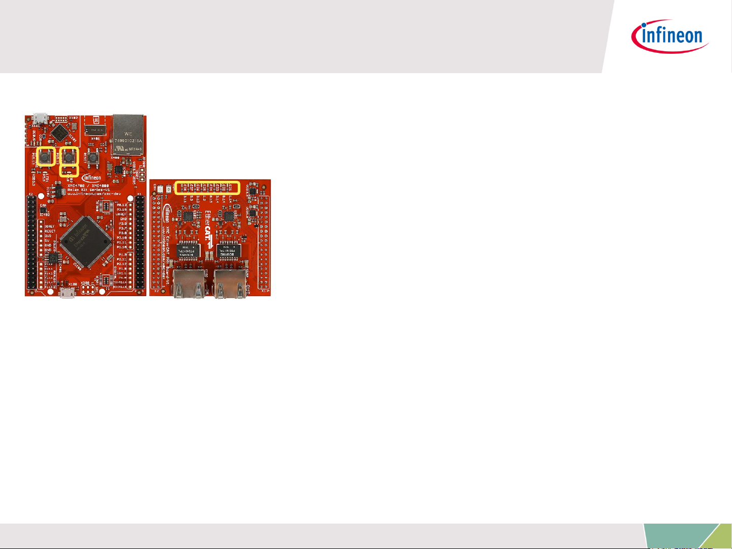
Requirements
XMC4800 Relax EtherCAT Kit
RJ45 Ethernet Cable
Windows Laptop installed
- DAVE v4 (Version4.1.4 or higher)
- TwinCAT2 or TwinCAT3 Master PLC
- Slave Stack Code Tool Version 5.12
Micro USB Cable (Debugger connector)
Copyright © Infineon Technologies AG 2016. All rights reserved.
5
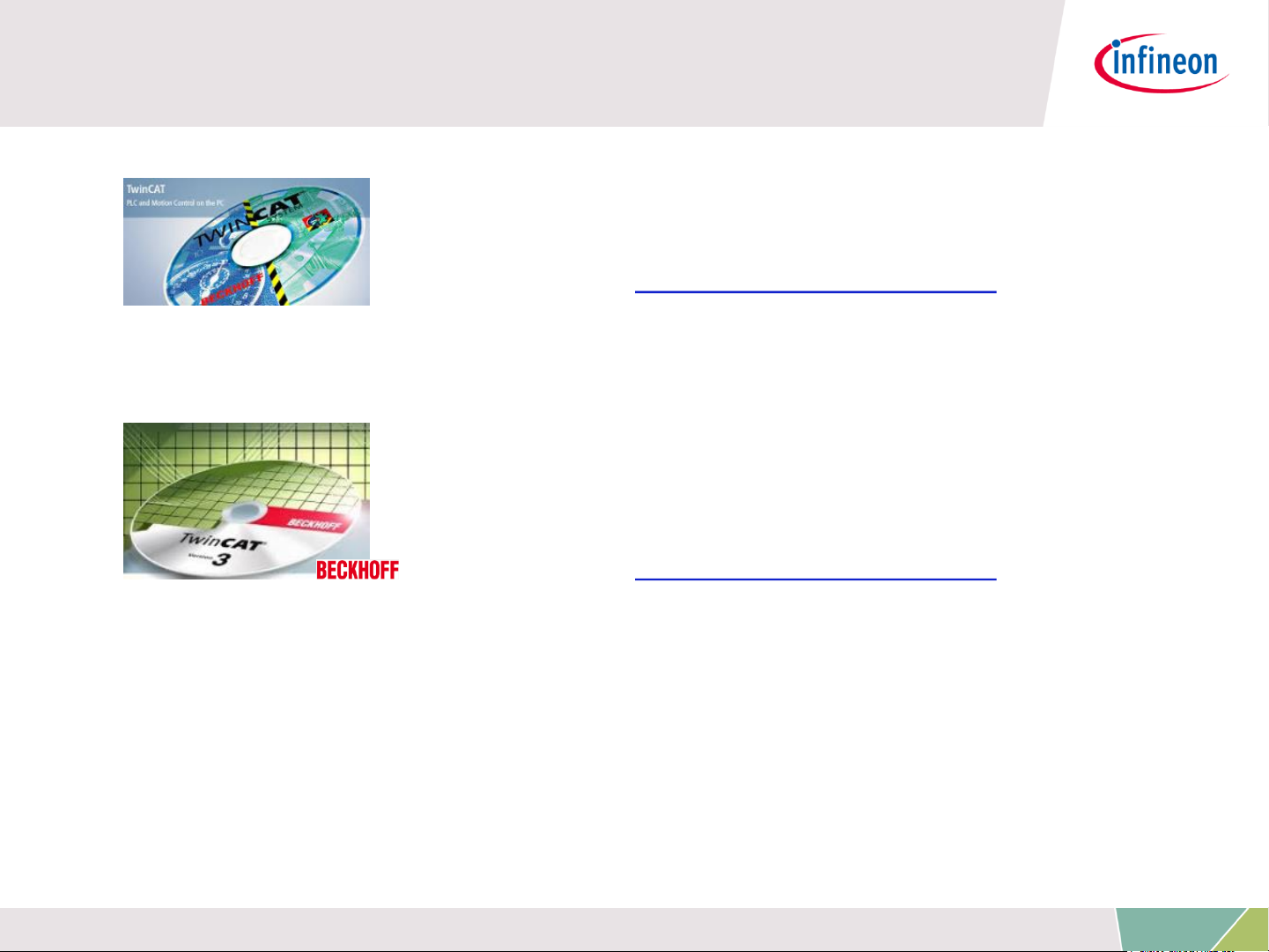
Requirements - free downloads
TwinCAT2 (30 day trial; 32bit Windows
only)
Link: Download TwinCAT2
or
TwinCAT3 (no trial period; usability limited;
32bit and 64bit Windows)
Link: Download TwinCAT3
ATTENTION: According our experience TwinCAT is best compatible
with Intel™ ethernet chipset.
For details on compatibility with your hardware, additional driver and
general installation support please get into contact with your local
BECKHOFF support.
Copyright © Infineon Technologies AG 2016. All rights reserved.
6
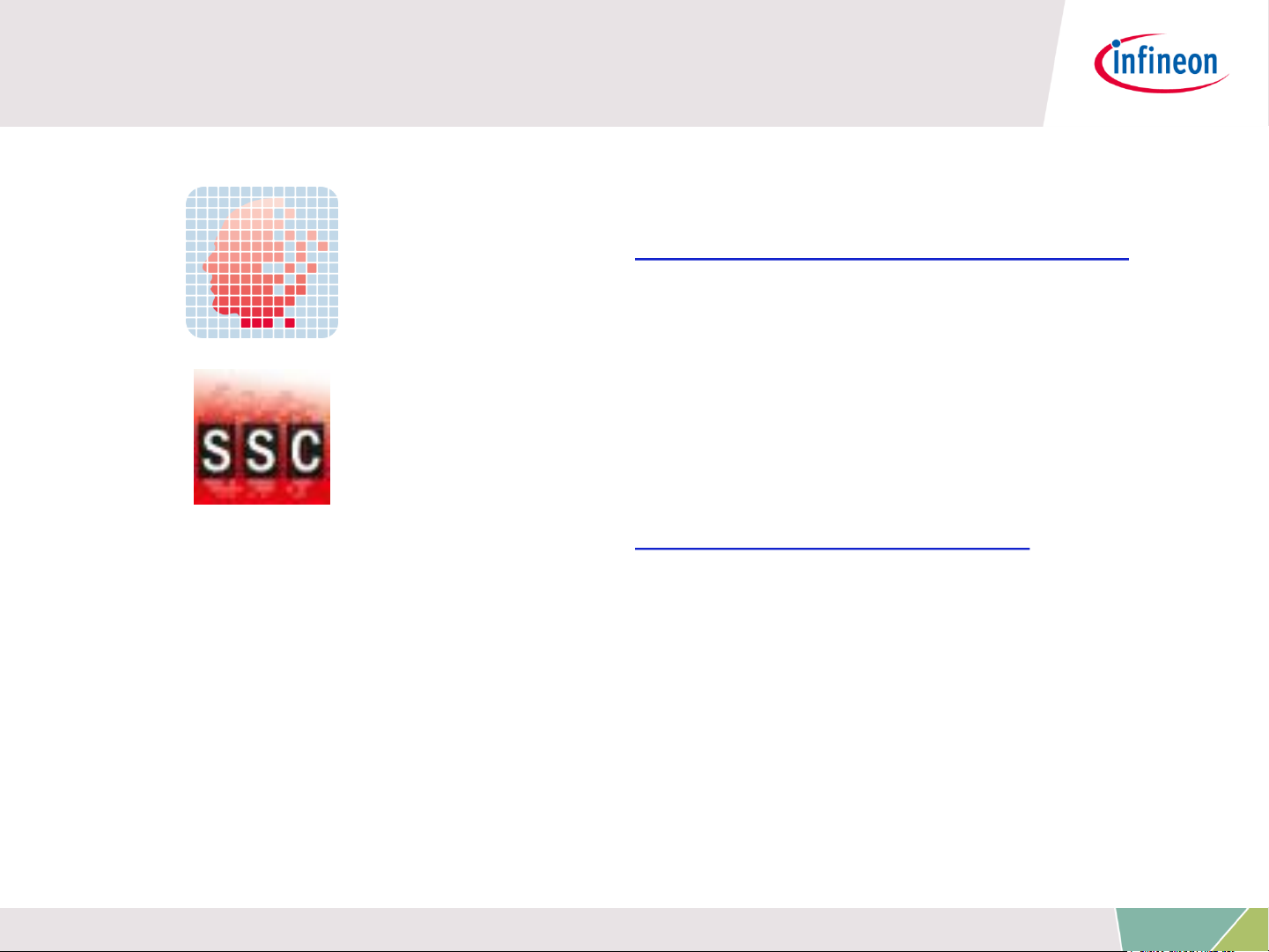
Requirements - free downloads
DAVE (v4.1.4 or higher)
Link: Download DAVE (Version 4)
EtherCAT Slave Stack Code Tool
Version 5.12
(ETG membership obligatory)
Link: Slave Stack Code Tool
Copyright © Infineon Technologies AG 2016. All rights reserved.
7

1
2
3
4
5
6
Overview and Requirements
Setup
Defining the interface of EtherCAT slave node
Generating Slave Stack Code and ESI file
Implementation of the application
How to test – using TwinCAT2 as host
7
How to test – using TwinCAT3 as host
Copyright © Infineon Technologies AG 2016. All rights reserved.
8
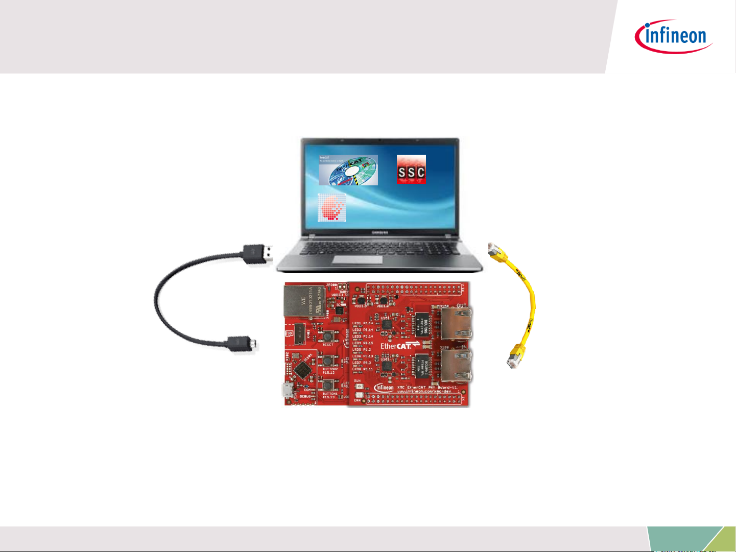
Setup – Hardware
Micro USB cable
Debugger
connected to
X101 debug
connector
Ethernet Cable
connected to
IN-port
Copyright © Infineon Technologies AG 2016. All rights reserved.
9
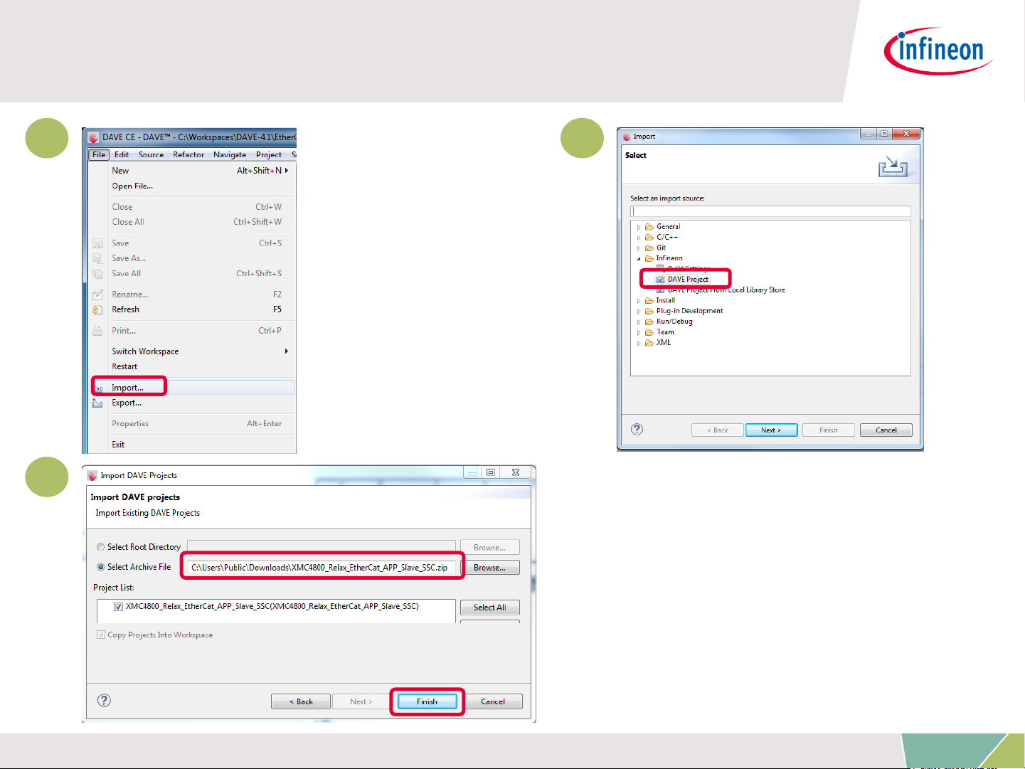
Setup – Import example project into DAVE
1. 2.
1 2
3
3.
Copyright © Infineon Technologies AG 2016. All rights reserved.
10

Setup – Import example project into DAVE
After the project import you will
find this project folder structure.
1
The project is nearly complete
for building, it only misses the
EtherCAT slave stack code. For
these files the Src folder has been
already prepared.
2
The EtherCAT slave stack code
for the XMC4800 can be generated
by configuration files. These
1
configuration files are included in
2
the project already.
The following slides show in detail
how to define your EtherCAT slave
node interface and to generate the
slave stack code.
Copyright © Infineon Technologies AG 2016. All rights reserved.
11

1
2
3
4
5
6
Overview and Requirements
Setup
Defining the interface of EtherCAT slave node
Generating Slave Stack Code and ESI file
Implementation of the application
How to test – using TwinCAT2 as host
7
How to test – using TwinCAT3 as host
Copyright © Infineon Technologies AG 2016. All rights reserved.
12
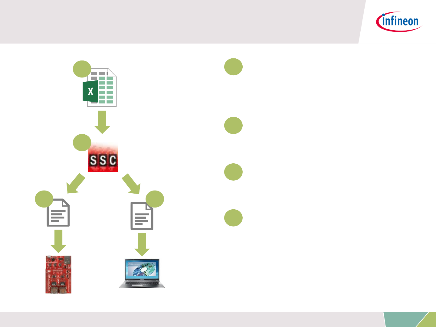
The flow to define the EtherCAT slave node
interface
1
1
Take the Excel Worksheet
provided inside the example
project to define your
EtherCAT slave node interface.
2
The Beckhoff SSC-tool uses
2
3 4
the excel sheet as an input to
generate the output-files.
3
The generated EtherCAT
slave stack code does apply
for the XMC4800.
4
The generated EtherCAT
Slave Information file (ESI)
does apply for the EtherCAT
host. There the relevant
interface information about the
slave is stored.
Copyright © Infineon Technologies AG 2016. All rights reserved.
13
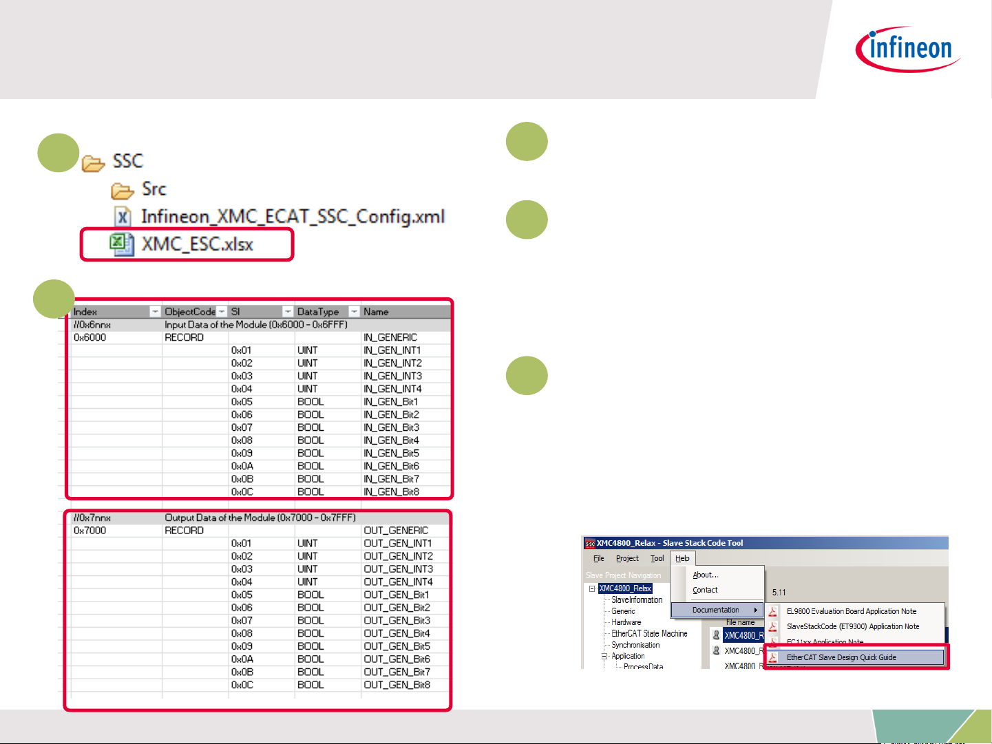
Defining the interface of EtherCAT slave node
1
1
Double click on the excel file
to open it.
2
Check the content of the file.
The data defined in both I/O
2
directions is 4x16bit integers
and 8x1bit booleans.
3
For further details on how to
define your own interface you
may want to follow the
instructions inside EtherCAT Slave
Design Quick Guide.pdf inside SSC
tool.
Copyright © Infineon Technologies AG 2016. All rights reserved.
14

1
2
3
4
5
6
Overview and Requirements
Setup
Defining the interface of EtherCAT slave node
Generating Slave Stack Code and ESI file
Implementation of the application
How to test – using TwinCAT2 as host
7
How to test – using TwinCAT3 as host
Copyright © Infineon Technologies AG 2016. All rights reserved.
15

Generating Slave Stack Code and ESI file
1
2
1
Start the tool and create a
new project File >> New
2
Select the configuration file
which you find inside the
example project.
Copyright © Infineon Technologies AG 2016. All rights reserved.
16
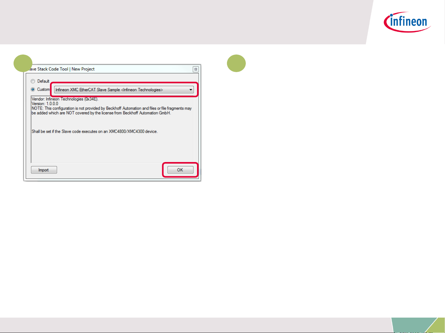
Generating Slave Stack Code and ESI file
3 3
Select the Infineon device
inside the drop down list and
confirm with the OK button.
Your project will be created.
Copyright © Infineon Technologies AG 2016. All rights reserved.
17
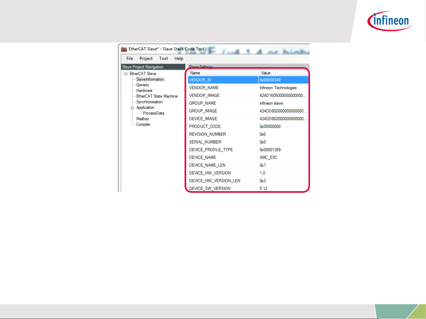
Generating Slave Stack Code and ESI file
› Check the settings inside SlaveInformation: vendor ID, vendor name,
product ID and product code are customer specific and are used by the host
to identify the slave.
› Define revision number, serial number, device name, HW/SW version
according to your needs.
› The vendor ID/name and product code assigned to infineon may be used for
evaluation purpose only. For productive purpose your own vendor ID/name
assigned by the EtherCAt Technology Group is obligatory.
Copyright © Infineon Technologies AG 2016. All rights reserved.
18
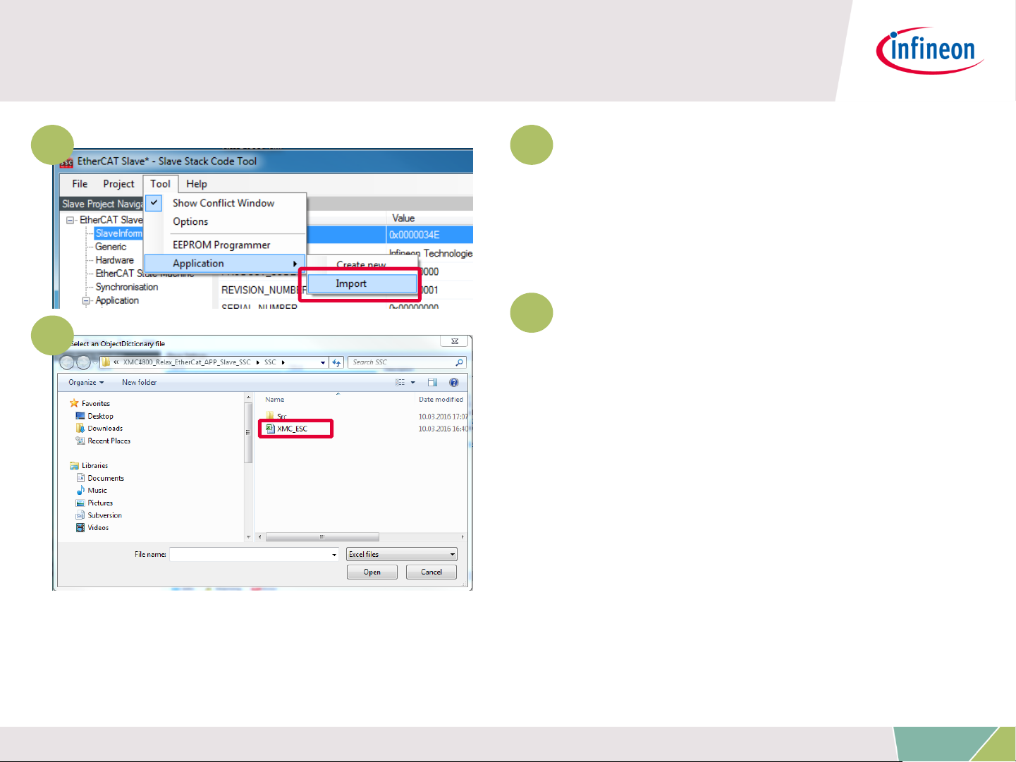
Generating Slave Stack Code and ESI file
4 4
Import the EXCEL-sheet
which defines the interface of
your EtherCAT node.
5
Select the EXCEL-file
5
provided inside the example
project.
Copyright © Infineon Technologies AG 2016. All rights reserved.
19

Generating Slave Stack Code and ESI file
6
6
Click on Project >> Create
new Slave Files
to start file generation.
7
In this step the destination
folder for the EtherCAT Slave
Stack Code and the ESI file can
be adapted. For this example it
is recommended to take the
default settings.
7
Copyright © Infineon Technologies AG 2016. All rights reserved.
20

Find and use your result
After the generation process the respective
8
files are inside the project space:
8
Check the availability of the generated
slave stack code
9
Check the availability of the ESI-file and
download to the host by these 3 steps:
1. Stop TwinCAT System Manager
2. Copy the ESI file to resp. destination
for TwinCAT2:
C:\TwinCAT\Io\EtherCAT
for TwinCAT3:
C:\TwinCAT\3.1\Config\Io\EtherCAT
3. Restart TwinCAT System Manager to
start re-work of the device description
cache.
9
10
Rebuild the DAVE project with the new
files.
Copyright © Infineon Technologies AG 2016. All rights reserved.
21

1
2
3
4
5
6
Overview and Requirements
Setup
Defining the interface of EtherCAT slave node
Generating Slave Stack Code and ESI file
Implementation of the application
How to test – using TwinCAT2 as host
7
How to test – using TwinCAT3 as host
Copyright © Infineon Technologies AG 2016. All rights reserved.
22

Copy data from/to local data to/from ESC
memory
Inside the generated file XMC_ESC.c the link to your application
must be implemented. Modify the source code accordingly which
copies the application data to/from ESC memory to the local
application memory:
Originally generated code: Modified code:
Copyright © Infineon Technologies AG 2016. All rights reserved.
23

Implement application specific slave node
behaviour
Inside the generated file XMC_ESC.c file the function
APPL_Application is implemented. This function implements the
application specific code to handle input and output…
A) … from mainloop or
B) … if synchronisation is active from ISR
Inside main.c of the example, the function
void process_app(TOBJ7000 *OUT_GENERIC, TOBJ6000 *IN_GENERIC);
implements the mapping of the input/output data to buttons and
LEDs. Therefore please modify the function APPL_Application to call
process_app in the following way:
Originally generated code: Modified code:
Copyright © Infineon Technologies AG 2016. All rights reserved.
24

Description – process of input and output
Within the slave stack code the function process_app is called. This
process_app function process the binary output data (master->slave)
to set the LED1 to LED8 level on the XMC EtherCAT PHY Board. The
integer output data is used to set the duty cycle of the dimmable
LED2. The states of the buttons are checked and propagated to the
input data (slave->master).
Copyright © Infineon Technologies AG 2016. All rights reserved.
25
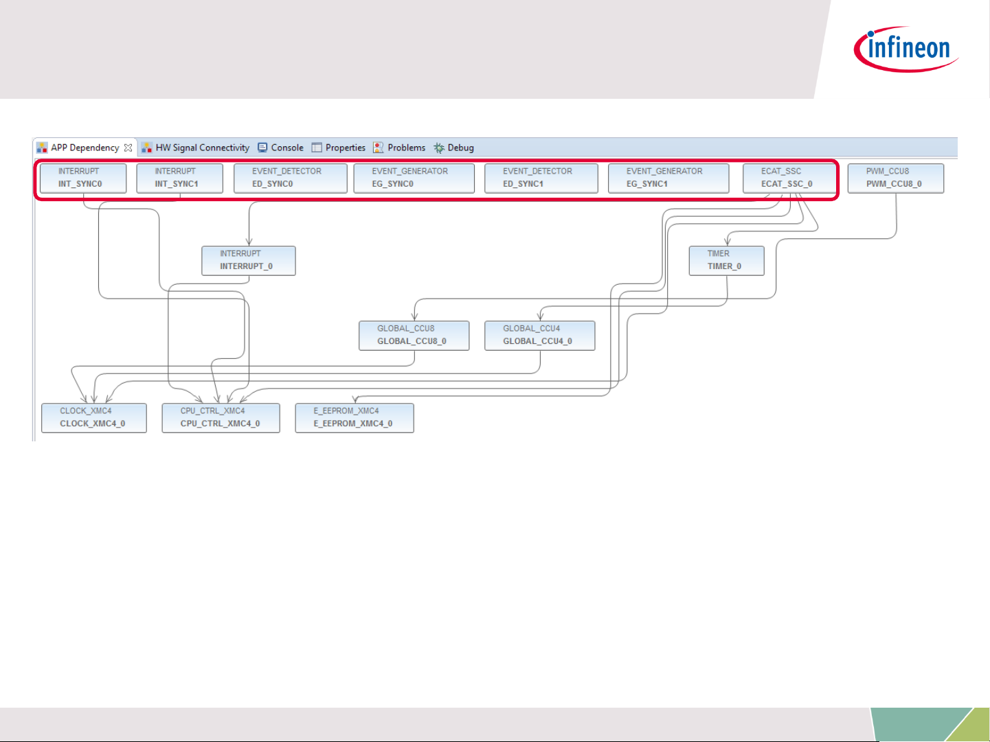
Description – Overview on used APPs
The ECAT_SSC APP assigns the system resources (automatically done
by DAVE by using the respective lower level apps) and pins (by
manual configuration) to setup a proper EtherCAT communication. The
EVENT_DETECTOR, EVENT_GENERATOR and INTERRUPT APPs are
used inside this example to connect the sync_out_0 and sync_out_1
of the ECAT_SSC APP to the interrupt service routines of the SSCstack.
Copyright © Infineon Technologies AG 2016. All rights reserved.
26
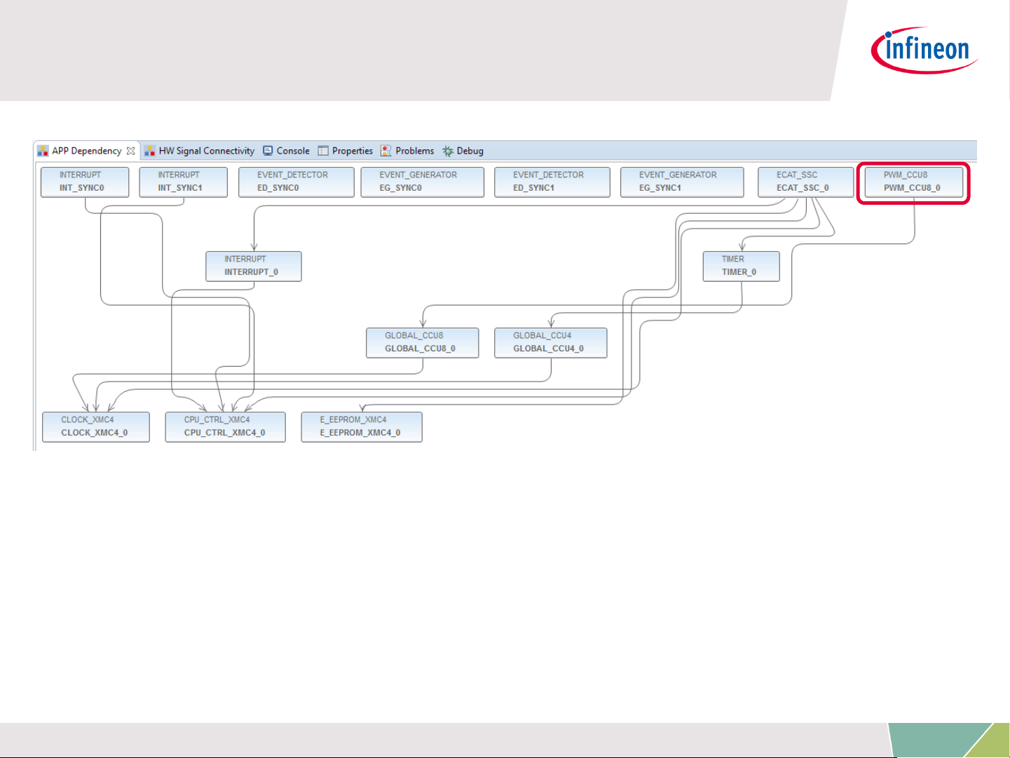
Description – Overview on used APPs
PWM_CCU8 APP is used to control the dimming level of the LED2 on
your Relax Kit and to assign the PWM output to the respective pin.
Copyright © Infineon Technologies AG 2016. All rights reserved.
27

Description – EtherCat ports and physical
connection
1
1
Right click on the ECAT_SSC APP.
From the context menu select
„Manual Pin Allocator“ to open the
pin allocation for the EtherCAT
module.
2 2
Inside Manual Pin Allocator you
can configure the EtherCAT ports for
your application. For the example
provided, the configuration fits to
the XMC4800 Relax EtherCAT Kit.
Copyright © Infineon Technologies AG 2016. All rights reserved.
28
Description – Distributed clock support
INTERRUPT(sync0)
sr_irq
ECAT_SSC0
sync_out_0
sync_out_1
EVENT_DETECTOR
signal_b trigger_out
EVENT_GENERATOR
trigger_in iout
EVENT_DETECTOR
signal_a
trigger_out
EVENT_GENERATOR
trigger_in iout
INTERRUPT(sync1)
sr_irq
For distributed clock support, the sync0 and sync1 signals coming
from the ethercat peripheral are used to trigger interrupts. Inside the
interrupt service routines the respective API functions of the SSC
protocol stack are called.
Copyright © Infineon Technologies AG 2016. All rights reserved.
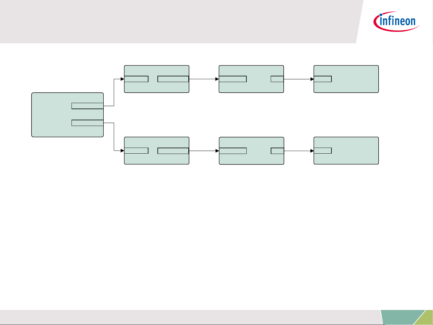
29

Description – Overview on propagating the
sync0 and sync1 signals to ISR
INTERRUPT(sync0)
sr_irq
ECAT_SSC0
sync_out_0
sync_out_1
EVENT_DETECTOR
signal_b trigger_out
EVENT_GENERATOR
trigger_in iout
EVENT_DETECTOR
signal_a
trigger_out
EVENT_GENERATOR
trigger_in iout
INTERRUPT(sync1)
sr_irq
EVENT_DETECTOR and EVENT_GENERATOR APPs are instances of the
event request unit (ERU) peripheral. Inside this example the ERU is
used to propagate the signals sync0 and sync1 to the interrupt service
routines.
Please see next slides how to setup this configuration inside DAVE™.
ATTENTION: With the same approach sync0 and sync1 signals can
also be connected to other resources. For example: ADC, ports and
timers.
Copyright © Infineon Technologies AG 2016. All rights reserved.
30
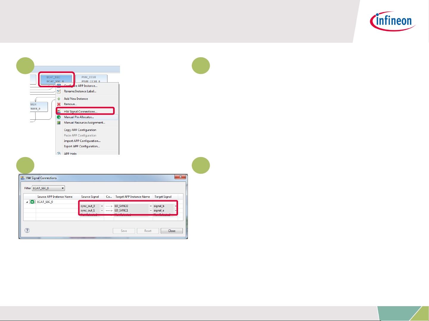
Description – DAVE™settings for distributed
clock support
1
1
Right click on the ECAT_SSC APP.
From the context menu select „HW
Signal Connections “ to open the
HW Signal Connection dialog of the
ECAT_SSC APP.
2 2
Connect the sync_out_0 and
sync_out_1 signal to the a/b input
of the event detection units.
Copyright © Infineon Technologies AG 2016. All rights reserved.
31

Description – DAVE™settings for distributed
clock support
3
3
Double click on the
EVENT_DETECTOR APP for SYNC0
and EVENT_DETECTOR APP for
SYNC1.
4 4
Select the respective source
signal („A“ for SYNC0 and „B“ for
SYNC1) and edge detection „Rising
Edge“.
Copyright © Infineon Technologies AG 2016. All rights reserved.
32
Description – DAVE™settings for distributed
clock support
5
6
5
Right click on the
EVENT_DETECTOR APP for SYNC0
and SYNC1. From the context menu
select „HW Signal Connections “ to
open the HW Signal Connection
dialog of the ECAT_SSC APP.
6
Connect the trigger_out signals
of the event detection units to the
trigger_in signals of the event
generation units.
Copyright © Infineon Technologies AG 2016. All rights reserved.
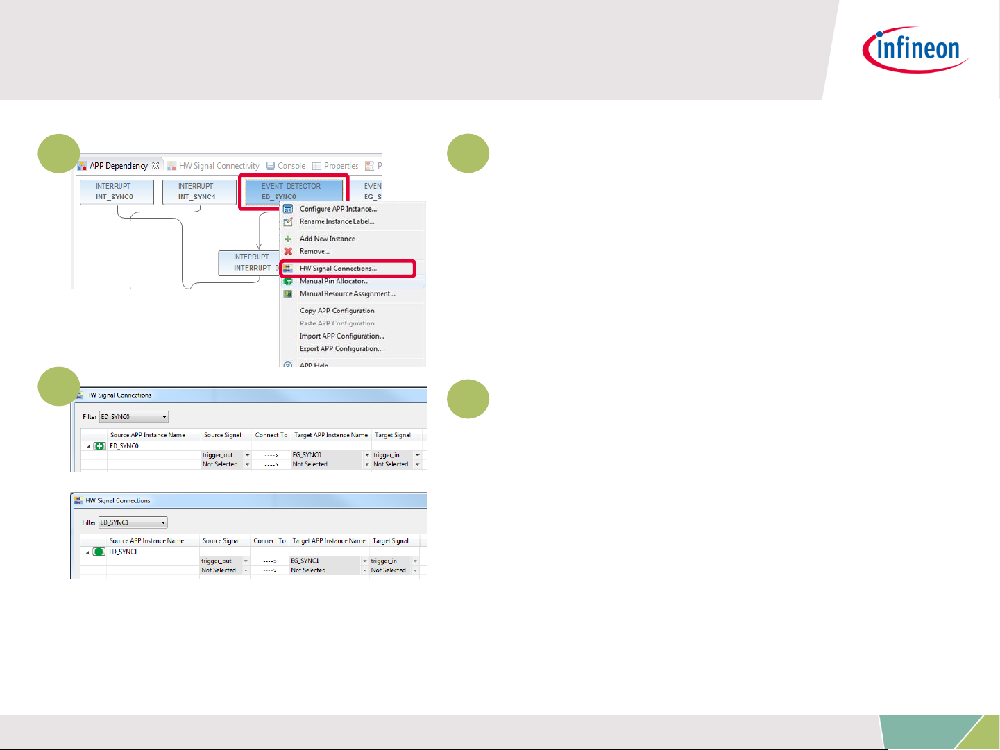
33

Description – DAVE™settings for distributed
clock support
7
8
7
Right click on
EVENT_GENERATOR for sync0 and
sync1. From the context menu
select „HW Signal Connections “ to
open the HW Signal Connection
dialog of the EVENT_GENERATOR
APP.
8
Connect the iout of the
EVENT_GENERATOR APP for sync0
to INTERRUPT APP of sync0.
Proceed respectively for sync1.
Copyright © Infineon Technologies AG 2016. All rights reserved.
34

Description – DAVE™settings for distributed
clock support
9
10
9
Double click on the INTERRUPT
APP for sync0 and INTERRUPT for
sync1.
10
2
Set the interrupt service routine
for sync0 and sync1 inside the
configuration of the respective
INTERRUPT APP.
Copyright © Infineon Technologies AG 2016. All rights reserved.
35

Description – DAVE™settings for distributed
clock support
Inside main() the interrupt handlers for sync0 and sync1 are
implemented. The implementation is calling the respective
functions of the SSC protocol stack.
Copyright © Infineon Technologies AG 2016. All rights reserved.
36

Description – Setup PWM for dimmable LED2
on P5.8
For driving the dimmable LED2
on the XMC4800 Relax
EtherCAT Kit the DAVE App
PWM_CCU8 is used. The PWM
is set to start during
initialization, frequency is
500Hz and the initial duty cycle
is set to 50%. The pin P5.8 is
allocated to channel1 of CCU8
inside the manual pin allocator
(right-click PWM_CCU8 APP).
Copyright © Infineon Technologies AG 2016. All rights reserved.
37

Description – SSC specific enabling/disabling
of interrupts [1/2]
Please see ET9300 application note published by the ETG on details
about the SSC code structure and interrupt handling (chapter 4).
In v1.8/2017-11-14 of this document inside chapter 5/hardware
access it is specified:
„If interrupts are used also two macros shall be defined
“ENABLE_ESC_INT” and “DISABLE_ESC_INT”. These shall
enable/disable all four interrupt sources”.
These macros are implemented inside ECAT_APP. Timer- and PDIinterrupt are handled by the ECAT_APP. As Sync0 and Sync1 are
routed through ERU (see before) these interrupts need to be
handled in addition by the user.
For this purpose ECAT_APP is implementing a callback function for
user specific implementation:
ENABLE_ESC_INT_USER and DISABLE_ESC_INT_USER.
Copyright © Infineon Technologies AG 2016. All rights reserved.
38

Description – SSC specific enabling/disabling
of interrupts [2/2]
Within this example you find the implementation of
ENABLE_ESC_INT_USER and DISABLE_ESC_INT_USER inside
main.c:
Copyright © Infineon Technologies AG 2016. All rights reserved.
39

Description – initialization inside main.c
Inside main() DAVE and its APPs (PWM_CCU8, ECAT_SSC) are
initialized. InitECAT_Adapt_LED() and Init_Relax-Button() are used to
initialize the buttons and LED1 to 8 of the „XMC EtherCAT PHY Board“.
Finally the MainLoop is called cyclically to process the state machine of
the slave stack code.
Copyright © Infineon Technologies AG 2016. All rights reserved.
40

1
2
3
4
5
6
Overview and Requirements
Setup
Defining the interface of EtherCAT slave node
Generating Slave Stack Code and ESI file
Implementation of the application
How to test – using TwinCAT2 as host
7
How to test – using TwinCAT3 as host
Copyright © Infineon Technologies AG 2016. All rights reserved.
41

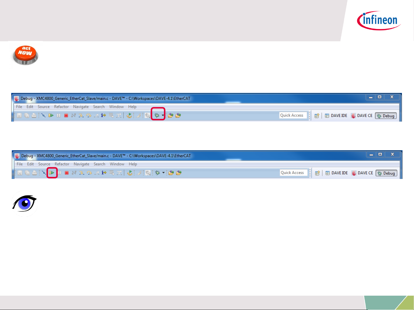
How to test – start the slave to run
ACTIONS
1. Build and download the example application software to the
XMC4800 and start the debugger
2. Start the software by the run button
OBSERVATIONS
1. The ERR-LED on the "XMC EtherCAT PHY Board" will turn on and
immediately turn off again.
2. The LED2 on the "XMC4800 Relax EtherCAT Kit" will remain turned
on.
Copyright © Infineon Technologies AG 2016. All rights reserved.
42
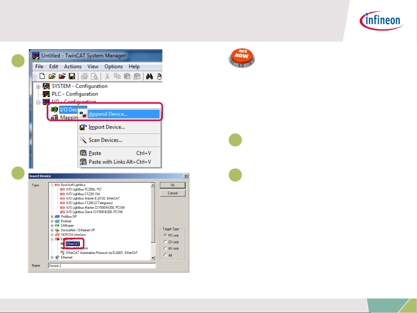
How to test – start the TwinCAT 2 master to
run (1/4)
1
2
ACTIONS
After starting the TwinCAT
System Manager from
windows start menu:
1
1 Right Click I/O-Devices
and select „Append Device…“
2
2 Create an EtherCAT
master device by double click
Copyright © Infineon Technologies AG 2016. All rights reserved.
43

How to test – start the TwinCAT 2 master to
run (2/4)
3
4
ACTIONS
3
3 Select the network adapter
you want to use (search and
select).
Application hint:
In case the device is not
found please install the
respective device driver by
following the instructions
given by TwinCAT through
the „Compatible Devices…“
button.
4
4 Right Click EtherCAT
master and select „Scan
Boxes…“
Copyright © Infineon Technologies AG 2016. All rights reserved.
44

How to test – start the TwinCAT 2 master to
run (3/4)
1
2
OBSERVATIONS
1
The slave appears as a node
on the EtherCAT master bus.
2
The RUN-LED is flashing
indicating PREOP-state
Copyright © Infineon Technologies AG 2016. All rights reserved.
45

How to test – start the TwinCAT 2 master to
run (4/4)
3
OBSERVATIONS
3
EtherCAT master view:
Inside the EtherCAT master
online state you see the
queued frames counting up,
the connected slave and its
PREOP state.
4
EtherCAT slave view:
4
The PREOP-state of the
slave is indicated within the
TwinCAT system manager .
Copyright © Infineon Technologies AG 2016. All rights reserved.
46

How to test – Setting slave to operational
mode
ACTION
Set master device to free run mode
OBSERVATIONS
1
EtherCAT slave view:
1
Online status of slave shows
the slave in OP state
2
EtherCAT master view:
Online status of master shows
the slave in OP state. Frames
2
are no more queued. Cyclic
counter is incrementing.
3
„XMC EtherCAT PHY Board“:
RUN-LED is static turned on
indicating OP-state.
Copyright © Infineon Technologies AG 2016. All rights reserved.
47

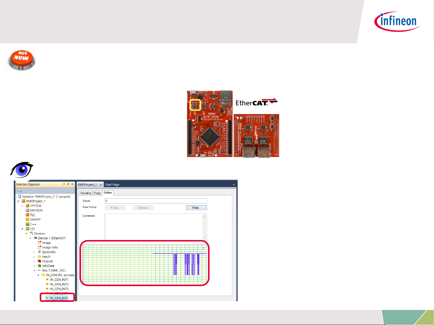
How to test – Monitoring slave inputs on
master
ACTIONS
While pushing Button1 on „XMC4800 Relax EtherCAT Kit“ the button
state is updated on the host.
OBSERVATIONS
State of IN_GEN_Bit1 changes
according to the state of
BUTTON1. Same is true for
IN_GEN_Bit2 and BUTTON2.
Copyright © Infineon Technologies AG 2016. All rights reserved.
48

How to test – Setting slave outputs on master
(1/2)
ACTIONS
Right click on OUT_GEN_Bit1 of the slave node and select „Online
Write…“ inside the context menu. Change the value from 0 to 1 to
switch on LED1/ from 1 to 0 to switch off LED1.
OBSERVATION
LED1 „XMC EtherCAT PHY Board“ is turned on/off according to
OUT_GEN_Bit1 setting.
Copyright © Infineon Technologies AG 2016. All rights reserved.
49

How to test – Setting slave outputs on master
(2/2)
ACTION
1. Right click on OUT_GEN_INT1 of the slave node and select „Online
Write…“ inside the context menu. Change the value from 0 to 50000.
OBSERVATION
1. Brightness of LED2 on „XMC4800 Relax EtherCAT Kit“ is dimmed.
The OUT_GEN_INT1 value sets the brightness of LED 2. The lower the
value the brighter the LED2. To turn off LED2 just set value to max
(65535).
Copyright © Infineon Technologies AG 2016. All rights reserved.
50

1
2
3
4
5
6
Overview and Requirements
Setup
Defining the interface of EtherCAT slave node
Generating Slave Stack Code and ESI file
Implementation of the application
How to test – using TwinCAT2 as host
7
How to test – using TwinCAT3 as host
Copyright © Infineon Technologies AG 2016. All rights reserved.
51
How to test – start the slave to run
ACTIONS
1. Build and download the example application software to the
XMC4800 and start the debugger
2. Start the software by the run button
OBSERVATIONS
1. The ERR-LED on the "XMC EtherCAT PHY Board" will turn on and
immediately turn off again.
2. The LED2 on the "XMC4800 Relax EtherCAT Kit" will remain turned
on.
Copyright © Infineon Technologies AG 2016. All rights reserved.
52

How to test – start the TwinCAT 3 master to
run (1/4)
1
2
ACTIONS
After starting the TwinCAT
System Manager from
windows start menu:
1
1 Right Click I/O-Devices
and select „Add New Item…“
2
2 Create an EtherCAT
master device by double click
Copyright © Infineon Technologies AG 2016. All rights reserved.
53

How to test – start the TwinCAT 3 master to
run (2/4)
3
4
ACTIONS
3
3 Select the network adapter
you want to use (search and
select).
Application hint:
In case the device is not
found please install the
respective device driver by
following the instructions
given by TwinCAT through
the „Compatible Devices…“
button.
4
4 Right Click EtherCAT
master and select „Scan
Boxes…“
Copyright © Infineon Technologies AG 2016. All rights reserved.
54

How to test – start the TwinCAT 3 master to
run (3/4)
1
2
OBSERVATIONS
1
The slave appears as a node
on the EtherCAT master bus.
2
The RUN-LED is flashing
indicating PREOP-state
Copyright © Infineon Technologies AG 2016. All rights reserved.
55

How to test – start the TwinCAT 3 master to
run (4/4)
3
OBSERVATIONS
3
EtherCAT master view:
Inside the EtherCAT master
online state you see the
queued frames counting up,
the connected slave and its
PREOP state.
4
EtherCAT slave view:
4
The PREOP-state of the
slave is indicated within the
TwinCAT system manager .
Copyright © Infineon Technologies AG 2016. All rights reserved.
56

How to test – Setting slave to operational
mode
ACTION
Set master device to free run mode
OBSERVATIONS
1
EtherCAT slave view:
1
Online status of slave shows
the slave in OP state
2
EtherCAT master view:
Online status of master shows
the slave in OP state. Frames
2
are no more queued. Cyclic
counter is incrementing.
3
„XMC EtherCAT PHY Board“:
RUN-LED is static turned on
indicating OP-state.
Copyright © Infineon Technologies AG 2016. All rights reserved.
57
How to test – Monitoring slave inputs on
master
ACTIONS
While pushing Button1 on „XMC4800 Relax EtherCAT Kit“ the button
state is updated on the host.
OBSERVATIONS
State of IN_GEN_Bit1 changes
according to the state of
BUTTON1. Same is true for
IN_GEN_Bit2 and BUTTON2.
Copyright © Infineon Technologies AG 2016. All rights reserved.
58

How to test – Setting slave outputs on master
(1/2)
ACTIONS
Right click on OUT_GEN_Bit1 of the slave node and select „Online
Write…“ inside the context menu. Change the value from 0 to 1 to
switch on LED1/ from 1 to 0 to switch off LED1.
OBSERVATION
LED1 „XMC EtherCAT PHY Board“ is turned on/off according to
OUT_GEN_Bit1 setting.
Copyright © Infineon Technologies AG 2016. All rights reserved.
59

How to test – Setting slave outputs on master
(2/2)
ACTION
1. Right click on OUT_GEN_INT1 of the slave node and select „Online
Write…“ inside the context menu. Change the value from 0 to 50000.
OBSERVATION
1. Brightness of LED2 on „XMC4800 Relax EtherCAT Kit“ is dimmed.
The OUT_GEN_INT1 value sets the brightness of LED 2. The lower the
value the brighter the LED2. To turn off LED2 just set value to max
(65535).
Copyright © Infineon Technologies AG 2016. All rights reserved.
60

 Loading...