

Page 1

Application Note Please read the Important Notice and Warnings at the end of this document V2.0
www.infineon.com page 1 of 26 2021-03-18
AN602
Radar Baseboard XMC4700
24 GHz radar system platform
B o ar d v e r si o n V 2.0
About this document
Scope and purpose
This application note describes the key features of Infineon’s Radar Baseboard XMC4700, part of Infineon’s 24
GHz radar system platform. It also introduces the concept of the platform, which supports multiple sensors. At
the heart of the board is the XMC4700, a 32-bit Arm® Cortex®-M4 MCU. It also has a high-speed USB 2.0 interface
to host a computer for visualization or fast data processing. In addition, the board is compatible with the
Arduino standard, which facilitates access to existing mass-market daughter boards for mass data storage or
wireless communication Arduino boards.
Intended audience
This document is intended for anyone working with Infineon’s 24 GHz radar system platform.
Related documents
Additional information can be found in the supplementary documentation provided with the Sense2GoL Pulse
or Distance2GoL Kits in the Infineon Toolbox or from www.infineon.com/24GHz:
• 24 GHz Radar Tools and Development Environment User Manual
• Sense2GoL Pulse Application Note (AN598)
• Distance2GoL Application Note (AN615)
Page 2

Application Note page 2 of 26 V2.0
2021-03-18
Radar Baseboard XMC4700
24 GHz radar system platform
Table of contents
Table of contents
About this document ....................................................................................................................... 1
Table of contents ............................................................................................................................ 2
List of figures ................................................................................................................................. 3
List of tables .................................................................................................................................. 4
1 Introduction .......................................................................................................................... 5
1.1 Key features ............................................................................................................................................. 5
2 Hardware description: Radar Baseboard XMC4700 ..................................................................... 6
2.1 Overview .................................................................................................................................................. 6
2.2 Block diagram .......................................................................................................................................... 7
2.3 Power supply ........................................................................................................................................... 7
2.3.1 Battery and external power supply ................................................................................................... 8
2.3.1.1 Hardware changes (for V1.1 only) ................................................................................................ 8
2.3.1.2 External power supply operation with battery charging............................................................. 9
2.3.3 USB operation .................................................................................................................................. 11
2.4 Current measurement of radar sensor shields .................................................................................... 12
2.5 EEPROM ................................................................................................................................................. 12
2.6 Microcontroller unit – XMC4700 ............................................................................................................ 13
2.7 User-configurable LEDs ......................................................................................................................... 13
2.8 User-configurable button ..................................................................................................................... 14
2.9 SD card reader ....................................................................................................................................... 14
2.10 Level shifters .......................................................................................................................................... 14
3 Connectors ........................................................................................................................... 16
4 Firmware development and debugging ................................................................................... 19
4.1 Debugging .............................................................................................................................................. 19
4.1.1 Onboard debugger and UART connection ...................................................................................... 21
5 Frequency band and regulations ............................................................................................. 22
5.1 24 GHz regulations ................................................................................................................................ 22
5.2 Regulations in Europe ........................................................................................................................... 22
5.3 Regulations in the United States of America ........................................................................................ 22
6 Authors ................................................................................................................................ 23
7 References ........................................................................................................................... 24
Revision history............................................................................................................................. 25
Page 3

Application Note page 3 of 26 V2.0
2021-03-18
Radar Baseboard XMC4700
24 GHz radar system platform
List of figures
List of figures
Figure 1 Radar Baseboard XMC4700 with main components and dimensions .............................................. 6
Figure 2 Block diagram – Radar Baseboard XMC4700 ..................................................................................... 7
Figure 3 Block diagram – power supply concept ............................................................................................. 8
Figure 4 P8 header configuration for using battery or external power supply ............................................... 8
Figure 5 External power supply and battery charging – block diagram .......................................................... 9
Figure 6 External power supply and battery charging – schematic ................................................................ 9
Figure 7 Battery operation – block diagram ................................................................................................... 10
Figure 8 Battery operation – schematic ......................................................................................................... 10
Figure 9 Operation with USB cables ............................................................................................................... 11
Figure 10 Current sensors connections ............................................................................................................ 12
Figure 11 Block diagram – XMC4700 ................................................................................................................. 13
Figure 12 User-configurable LEDs ..................................................................................................................... 13
Figure 13 User-configurable button ................................................................................................................. 14
Figure 14 SD card reader connections .............................................................................................................. 14
Figure 15 Level translator (U6, U7 and U8) connections .................................................................................. 15
Figure 16 External headers – P2, P3, P4, P5 and P6.......................................................................................... 16
Figure 17 V1.1 Debugger components ............................................................................................................. 19
Figure 18 P8 header connections – for onboard debugger, for external debugger (V1.1 only)...................... 20
Figure 19 V2.0 Debugger components – For debugging and flashing, the USB cable has to be simply
connected to the “Debug USB” port. Header settings are no longer needed. .............................. 20
Figure 20 Recommended installation options for the J-Link driver ................................................................ 21
Page 4

Application Note page 4 of 26 V2.0
2021-03-18
Radar Baseboard XMC4700
24 GHz radar system platform
List of tables
List of tables
Table 1 User LEDs pin assignment ................................................................................................................. 14
Table 2 External header (P2) – pin description ............................................................................................. 16
Table 3 External header (P3) – pin description ............................................................................................. 17
Table 4 External header (P4) – pin description ............................................................................................. 17
Table 5 External header (P5) – pin description ............................................................................................. 17
Table 6 External header (P6) – pin description ............................................................................................. 17
Table 7 Debugger type and header settings (V1.1 only) ............................................................................... 20
Table 8 XMC4200 pins used for debugging and UART communication ....................................................... 21
Page 5

Application Note page 5 of 26 V2.0
2021-03-18
Radar Baseboard XMC4700
24 GHz radar system platform
Introduction
1 Introduction
The Radar Baseboard XMC4700 is a generic sensor interface for Infineon’s 24 GHz radar sensors. The central
MCU can perform radar data processing or forward the sensor data to a USB interface or an Arduino interface.
The board is designed to allow customers to do prototyping and system integrations as well as initial product
feature evaluations.
An onboard debugger with licensed firmware from SEGGER, it also allows easy debugging over USB. Infineon’s
powerful, free-of-charge toolchain DAVE™ can be used for programming the XMC4700 microcontroller. This
application note describes the key features and hardware configuration of the Radar Baseboard XMC4700 in
detail.
1.1 Key features
The primary features of the Radar Baseboard XMC4700 are:
• XMC4700 – 32-bit Arm® Cortex®-M4 based microcontroller for signal processing
• Multiple power supply possibilities – micro-USB, external power supply or battery
• Compatible with Arduino for ease of use and prototyping
• Current sensors for current consumption estimation
• Onboard debugger for debugging
• SD card reader for raw data storage
• User-configurable LEDs
• User-configurable button
Page 6
Application Note page 6 of 26 V2.0
2021-03-18
Radar Baseboard XMC4700
24 GHz radar system platform
Hardware description: Radar Baseboard XMC4700
2 Hardware description: Radar Baseboard XMC4700
This section presents a detailed overview of the Radar Baseboard XMC4700 hardware specifications, including
features, power supply and board interfaces.
2.1 Overview
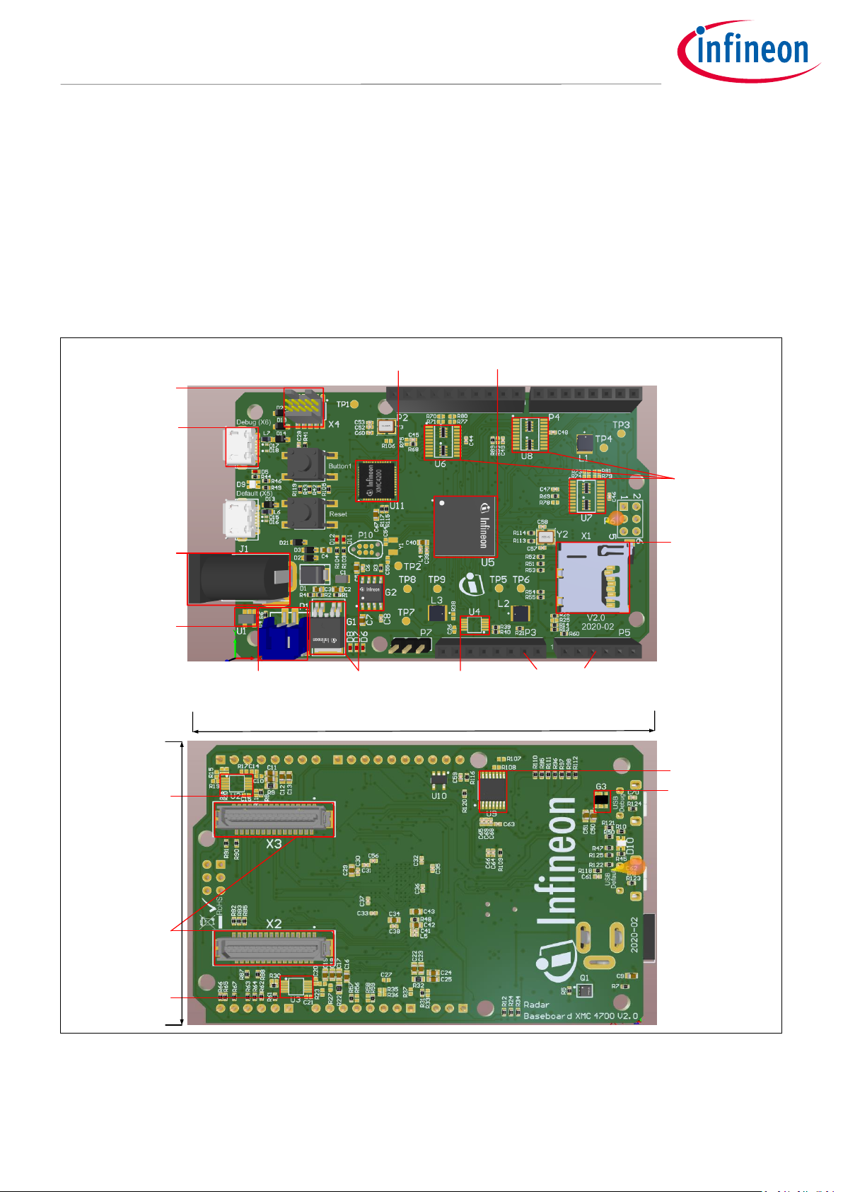
The Radar Baseboard XMC4700 is shown in Figure 1. The board makes it possible to implement different
settings to get closer to a custom-fit solution for the use case. It also makes it possible to quickly gather
sampled radar data that can be used to develop radar signal-processing algorithms on a PC or implement
target detection algorithms directly on the microcontroller using DAVE™.
XMC4200
debugger MCU
Cortex debugger
connector
Debug USB
External
power
connector
Linear charge
management
controller
LiPo battery
connector
LDO
Current
Sensor
Arduino-compatible
connectors
SD card
reader
XMC4700 MCU
Voltage level
tanslator
Current
Sensor
Current
Sensor
Connectors to
BGT24LTR11
Shield
LDO
J-K Flipflop
85 mm
55 mm
Figure 1 Radar Baseboard XMC4700 with main components and dimensions
Page 7
Application Note page 7 of 26 V2.0
2021-03-18
Radar Baseboard XMC4700
24 GHz radar system platform
Hardware description: Radar Baseboard XMC4700
2.2 Block diagram
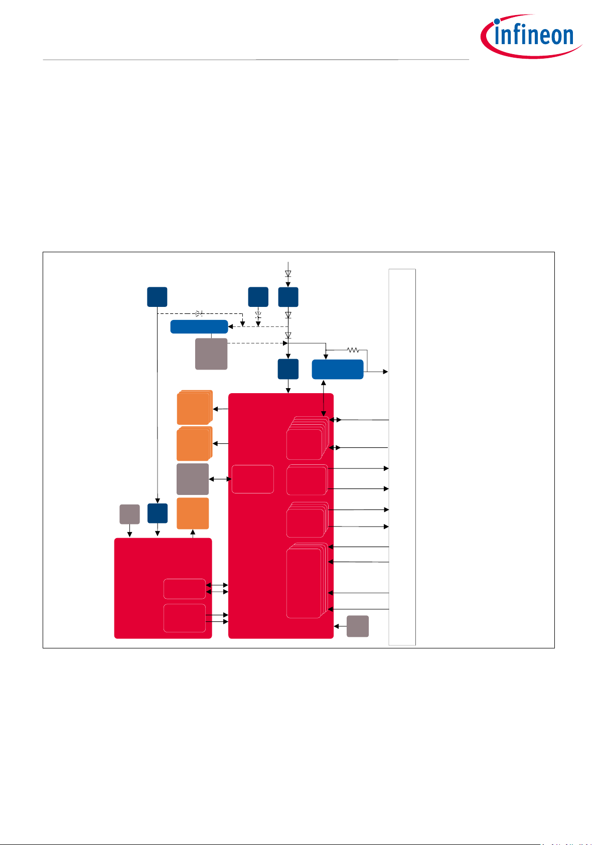
Figure 2 shows the block diagram of the Radar Baseboard XMC4700. It features Infineon’s XCM4700, 32-bit Arm®
Cortex®-M4 based microcontroller for signal processing. It has two connectors to interface with the RF shield.
The board also has several debugging possibilities such as Tag connect, cortex connector and also an onboard
debugger. For user flexibility, it has three configurable LEDs that can be used for status indication and also a
configurable button. A SD card reader is also available for data storage.
The board is powered via the micro-USB cables. It is also possible to power it via external 7 V power supply or
with a battery. A series of low-noise voltage regulators is used to provide a regulated power supply to the
different building blocks of the board and the connected shield. There are three current sensors on the board
for measuring current consumption of the connected shield or Arduino.
Connectors b/w Base Board and Radar Shield
ADC
ADC
ADC
ADC
CCU8
CCU4
USIC
XMC4700
SD card
reader
SDMMC
UART
SWD
SCK
Debug
LED
12
MHz
User LED
XMC4200
(Debugger)
12
MHz
LDO
LDO
LDO
3.3V
VCC1
R
shunt
7V
External Power Supply
5Vinput
5V
Battery
Micro
USB
Micro
USB
Battery Manager
Current Sensors
3.3V
5V
User LED
Figure 2 Block diagram – Radar Baseboard XMC4700
2.3 Power supply
The Radar Baseboard XMC4700 is powered via external 7 V power, battery or two micro-USB cables. Figure 3
shows the power supply concept used in the system.
Page 8
Application Note page 8 of 26 V2.0
2021-03-18
Radar Baseboard XMC4700
24 GHz radar system platform
Hardware description: Radar Baseboard XMC4700
Base board
XMC4700
LDO
VCC1
R
shunt
7V
External Power Supply
5Vinput
5V
Battery
Battery Manager
Current Sensors
3.3V
LDO
3.3V
5Vdebug
Micro
USB
XMC4200
(Debugger)
LDO
5Vinput
RF Shield
Micro
USB
Debug (X6)
Default (X5)
Figure 3 Block diagram – power supply concept
2.3.1 Battery and external power supply
The Radar Baseboard XMC4700 can be powered up with an external power supply (7 V) to operate the board. It
is also possible to charge the battery using an onboard battery manager. This section explains the battery
charging and external power supply feature of the board.
2.3.1.1 Hardware changes (for V1.1 only)
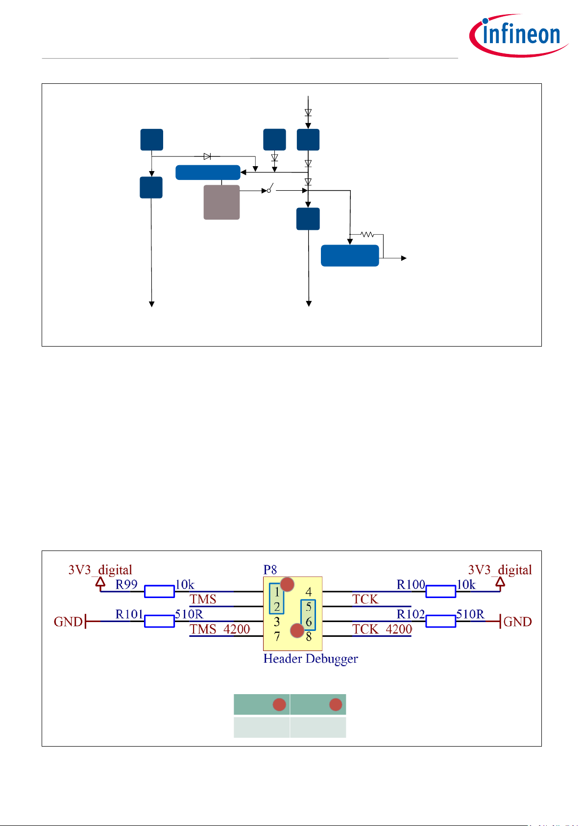
To start up the XMC4700 with external 7 V power supply or battery, it is important to first carry out these steps:
• Configure the P8 header as shown in Figure 4 (1, 2 connected and 5, 6 connected).
• Remove the P9 header to release the XMC4700 from RESET.
1
2
TCK
TMS
0 1
12
Main XMC4700 Normal Boot
Figure 4 P8 header configuration for using battery or external power supply
Page 9

Application Note page 9 of 26 V2.0
2021-03-18
Radar Baseboard XMC4700
24 GHz radar system platform
Hardware description: Radar Baseboard XMC4700
2.3.1.2 External power supply operation with battery charging
The Radar Baseboard XCM4700 allows the user to use an external 7 V power supply for operation or to charge
the battery. The block diagram of the circuitry is shown in Figure 5 and Figure 6. When the baseboard is
connected to an external power supply (7 V), the LDO (G1) has an input voltage and creates a stable 5 V voltage
(5 V
input
). This 5 V (5 V
input
) is then used by the battery manager (U1) to charge the battery. LED (D2) indicates the
charging status. The same 5 V (5 V
input
) is also used as an input to the second LDO (G2), which in turn generates
the stable 3.3 V to power the board components. The PMOS switch (Q1) remains off as the gate voltage is high,
hence keeping the battery output disconnected.
Base board
XMC4700
LDO
VCC1
R
shunt
7V
External Power Supply
5Vinput
5V
Battery
Battery Manager
Current Sensors
3.3V
LDO
3.3V
5Vdebug
Micro
USB
XMC4200
(Debugger)
LDO
5Vinput
RF Shield
Micro
USB
External supply and battery charging
Debug (X6)
Default (X5)
Battery charging
Note: Debugger is not operational when Ext 7V supply is used
Figure 5 External power supply and battery charging – block diagram
External Power Main Power
Charging battery
PMOS off
Vgs(+)
LED indicates the charging status
ON: Battery is detected/Battery is charging
OFF: Battery is disconnected/Battery is fully charged
LDO
LDO
Battery Manager
Figure 6 External power supply and battery charging – schematic
Page 10

Application Note page 10 of 26 V2.0
2021-03-18
Radar Baseboard XMC4700
24 GHz radar system platform
Hardware description: Radar Baseboard XMC4700
The operation of the baseboard using the battery is shown in Figure 7. When the baseboard is not connected to
an external power supply, the LDO (G1) has no input voltage and remains disabled. Consequently, the battery
manager (U1) has no input voltage and does not charge the battery. The gate voltage of the PMOS switch (Q1) is
low. The switch is then closed, creating a connection between the battery and the input of the second LDO (G2).
The battery supplies 4.2 V as an input to the LDO (G2) to generate the stable 3.3 V.
Base board
XMC4700
LDO
VCC1
R
shunt
7V
External Power Supply
5Vinput
5V
Battery
Battery Manager
Current Sensors
3.3V
3.3V
Micro
USB
XMC4200
(Debugger)
LDO
5Vinput
RF Shield
Micro
USB
Battery operation
5Vdebug
LDO
Default (X5)
Debug (X6)
Battery in use
Note: Debugger is not operational when battery is used
Figure 7 Battery operation – block diagram
No External Power Main Power
4.2 V
PMOS on
Vgs(-)
LDO
LDO
Battery Manager
4.2 V
Figure 8 Battery operation – schematic
Page 11

Application Note page 11 of 26 V2.0
2021-03-18
Radar Baseboard XMC4700
24 GHz radar system platform
Hardware description: Radar Baseboard XMC4700
2.3.3 USB operation
The baseboard can also be powered through two USB cables, as shown in Figure 9. It is also possible to use a
single USB cable for operation. However, single USB operation depends on the overall power consumption of
the baseboard and the radar shield attached to it. The battery manager is connected to the battery and,
depending on the current supplied by the USBs, charges the battery.
only X5 (Default) USB operation
only X6 (Debug) USB operation
X5, X6 USB operation
Base board
XMC4700
LDO
VCC1
R
shunt
7V
External Power Supply
5Vinput
5V
Battery
Battery Manager
Current Sensors
3.3V
3.3V
Micro
USB
XMC4200
(Debugger)
LDO
5Vinput
X6
RF Shield
Micro
USB
5Vdebug
LDO
Default (X5)
Battery charging
Note: Debugger is not operational when only Default USB is used
Base board
XMC4700
LDO
VCC1
R
shunt
7V
External Power Supply
5Vinput
5V
Battery
Battery Manager
Current Sensors
3.3V
3.3V
Micro
USB
XMC4200
(Debugger)
LDO
5Vinput
RF Shield
Micro
USB
5Vdebug
LDO
Default (X5)
Debug (X6)
Battery charging
Base board
XMC4700
LDO
VCC1
R
shunt
7V
External Power Supply
5Vinput
5V
Battery
Battery Manager
Current Sensors
3.3V
3.3V
Micro
USB
XMC4200
(Debugger)
LDO
5Vinput
Default (X5)
RF Shield
Micro
USB
5Vdebug
LDO
Debug (X6)
Battery charging
Figure 9 Operation with USB cables
Page 12

Application Note page 12 of 26 V2.0
2021-03-18
Radar Baseboard XMC4700
24 GHz radar system platform
Hardware description: Radar Baseboard XMC4700
2.4 Current measurement of radar sensor shields
The Radar GUI provides an estimate of the expected average power consumption for the configured settings.
This is done using the current sensors on the board (U2, U3 and U4). If a measurement of the actual operating
current consumption of the sensor is required, shunt resistors are provided on the Radar Baseboard XMC4700.
The shunt resistors (R9, R22 and R32) are in series to the supplies of the Radar Shield, as illustrated in Figure 10.
By measuring the voltage drop along the respective shunt resistor, the user can infer the current supplied to the
Radar Shield and multiply it by the voltage supplied to measure the power consumption. In this way, it is possible
to measure the power supplied on the 3.3 V and the 5 V supply of the connected Radar Shield or the Arduino
board.
Figure 10 Current sensors connections
2.5 EEPROM
When the board boots up or when a sensor is plugged into the sensor connectors, the sensor supply is
deactivated. During start-up, only the 3V3_digital (MCU) supply of the EEPROM on the radar shield is active. The
MCU detects if a radar shield is plugged into the connectors. If the radar shield is plugged in correctly, the MCU
will read the information in the EEPROM. This is how it will get information about what kind of shield is plugged
into the interface. The power supply of the radar shield is only enabled if a correct shield is detected.
Page 13

Application Note page 13 of 26 V2.0
2021-03-18
Radar Baseboard XMC4700
24 GHz radar system platform
Hardware description: Radar Baseboard XMC4700
2.6 Microcontroller unit – XMC4700
The Radar Baseboard XMC4700 uses an XMC4700 32-bit Arm® Cortex®-M4 MCU to perform the radar signal
processing. The XMC4700 takes care of communication with all the sub-systems on the radar module, enables
data acquisition, performs the complete radar signal processing (including sampling and FFT) and
communicates the results via its UART or USB interface to an external device.
An XMC4700 in a 194-pin BGA package is used, featuring a 144 MHz CPU frequency, 2048 kB Flash and 352 kB RAM.
Four 12-bit ADCs help to implement the radar signal sampling and also acquire the various sensor data from the
BGT24LTR11 MMIC. The MCU also has a USB 2.0 device interface, which enables direct communication with a PC.
Figure 11 shows a system block diagram of the XMC4000 series MCUs.
Please refer to the XMC4700/XMC4800 datasheet for detailed information on the microcontroller.
Figure 11 Block diagram – XMC4700
2.7 User-configurable LEDs
Pins of the XMC47000 on the Radar Baseboard are connected to external LEDs on the top and bottom of the
PCB for status indication. Table 1 lists the user-configurable LEDs pin assignment. There is a set of three LEDs
on each side of the PCB.
Figure 12 User-configurable LEDs
Page 14

Application Note page 14 of 26 V2.0
2021-03-18
Radar Baseboard XMC4700
24 GHz radar system platform
Hardware description: Radar Baseboard XMC4700
Table 1 User LEDs pin assignment
LED
MCU port pin
D9, D10 (red LED)
P1.15
D9, D10 (green LED)
P1.14
D9, D10 (blue LED)
P1.13
2.8 User-configurable button
The Radar Baseboard XMC4700 has a user-configurable button, S1, for additional functionality and flexibility for
the user. It is interfaced with XMC4700 at the P8.8 pin.
Figure 13 User-configurable button
2.9 SD card reader
The baseboard also has a SD card reader connected to the XMC4700’s SDMMC block. This SD card reader can be
used to collect and store raw data.
Figure 14 SD card reader connections
2.10 Level shifters
The baseboard has three level shifters (U6, U7 and U8), as shown in Figure 15, for translating logic voltage
levels.
Port A tracks VCCA (3V3_digital) and port B tracks VCCB (configurable using the P7 header to 3.3 V or 5 V). These
level translations are important for Arduino operation. When the Output Enable (OE) input is low, all outputs
are placed in the high-impedance state.
Page 15

Application Note page 15 of 26 V2.0
2021-03-18
Radar Baseboard XMC4700
24 GHz radar system platform
Hardware description: Radar Baseboard XMC4700
Figure 15 Level translator (U6, U7 and U8) connections
Page 16

Application Note page 16 of 26 V2.0
2021-03-18
Radar Baseboard XMC4700
24 GHz radar system platform
Connectors
3 Connectors
Figure 16 shows the pin headers on the Radar Baseboard XMC4700 and Table 2, 0, Table 4 and Table 5 describe
the pins.
2
1
345678910
12
34
5
678
1 2
3
4
5 6
1 2 3 4
5
6
3 4 5 6 7
8
1 2
Figure 16 External headers – P2, P3, P4, P5 and P6
Table 2 External header (P2) – pin description
Pin no.
Signal name
Pin description
1
ARD_Pin_D9
General-purpose IO
2
ARD_Pin_D10
PWM output
3
ARD_Pin_SPI_CS
SPI slave select (default)/PWM output
4
ARD_Pin_SPI_MOSI
SPI master out slave in (default)/PWM output
5
ARD_Pin_SPI_MISO
SPI master in slave out
6
ARD_Pin_SPI_CLK
SPI clock
7
GND
Ground
9
ARD_Pin_SDA
I2C data/Arduino ADC channel CH4
10
ARD_Pin_SCL
I2C clock/Arduino ADC channel CH5
Page 17

Application Note page 17 of 26 V2.0
2021-03-18
Radar Baseboard XMC4700
24 GHz radar system platform
Connectors
Table 3 External header (P3) – pin description
Pin no.
Signal name
Pin description
2
IOREF
Voltage reference at which the external board interfacing with the
Radar Baseboard XMC4700 is operating. Can be selected via P7.
3
RESET
Resets the Radar Baseboard XMC4700
4
VCC_ARD_4
3.3 V
5
VCC_ARD_5
5 V 6 GND
Ground
7
GND
Ground
Table 4 External header (P4) – pin description
Pin no.
Signal name
Pin description
1
ARD_Pin_UART_RX
XMC4700 UART receive
2
ARD_Pin_UART_TX
XMC4700 UART transmit
3
ARD_Pin_D3
External interrupt 0
4
ARD_Pin_D4
PWM output (default)/external interrupt 1
5
ARD_Pin_D5
Timer 0
6
ARD_Pin_D6
PWM output (default)/timer 1
7
ARD_Pin_D7
PWM output
8
ARD_Pin_D8
General-purpose IO
Table 5 External header (P5) – pin description
Pin no.
Signal name
Pin description
1
ARD_ADC_0
Arduino ADC channel CH0
2
ARD_ADC_1
Arduino ADC channel CH1
3
ARD_ADC_2
Arduino ADC channel CH2
4
ARD_ADC_3
Arduino ADC channel CH3
5
ARD_ADC_4/DAC.VCoarse
Arduino ADC channel CH4
6
ARD_ADC_5/DAC.VFine
Arduino ADC channel CH5
Table 6 External header (P6) – pin description
Pin no.
Signal name
Pin description
1
ARD_SPI2.MISO
SPI master in slave out
2
5V
5 V supply
3
ARD.SPI2.CLK
SPI clock
4
ARD_SPI2.MOSI
SPI master out slave in
5
RESET
Resets the Radar Baseboard XMC4700
6
GND
Ground
Page 18

Application Note page 18 of 26 V2.0
2021-03-18
Radar Baseboard XMC4700
24 GHz radar system platform
Connectors
Notes:
1. Pin 8 of header P2 is not connected to any signal.
2. Pins 1 and 8 of header P3 are not connected to any signal.
3. Pins on P2 and P4 can primarily be used as general-purpose IOs.
The pin headers significantly enhance the functionality of the module. They enable probing the analog outputs
of the sensor module and also probing various other signals provided to the IC. In principle, the accessibility of
several pins on the radar IC and the IF signals available via the external pin headers enable interfacing the
module with an external signal processor.
Page 19

Application Note page 19 of 26 V2.0
2021-03-18
Radar Baseboard XMC4700
24 GHz radar system platform
Firmware development and debugging
4 Firmware development and debugging
The Radar Baseboard XMC4700 comes with a default firmware that is intended to serve as a bridge between a
host (typically a PC) and the Radar shields, which are mounted on the connectors. For this, the firmware
implements logic to:
• communicate with the host via USB
• read radar sensor data via SPI
• perform signal processing on the received data from the shield
• provide control signals to the shield for specific tasks (for example, controlling the on/off of the radar
MMIC)
• check if a radar shield board is plugged into the connectors
• read and write the EEPROM on the radar shield board (for example, to identify the board)
• control some auxiliary peripherals such as status LEDs on the baseboard.
The firmware is delivered as a project for the DAVETM toolchain, enabling compiling, flashing and debugging work
out of the box by simply pressing the corresponding buttons in DAVETM.
4.1 Debugging
The board has several possibilities for debugging:
Onboard debugger – XMC4200 with debug USB
Tag connect (P10) – for tag connect debug cables
Cortex debug connector (X4) – 10-pin connector to enable external debugger to be connected
XMC4200
debugger MCU
Cortex debugger
connector
XMC boot level
jumper (P8)
Tag connect
Debug USB
Reset jumper (P9)
Figure 17 V1.1 Debugger components
Page 20

Application Note page 20 of 26 V2.0
2021-03-18
Radar Baseboard XMC4700
24 GHz radar system platform
Firmware development and debugging
Error! Reference source not found. and Error! Reference source not found. show the different header
settings for using different types of debuggers for V1.1.
Table 7 Debugger type and header settings (V1.1 only)
Debugger type
Header settings
Onboard debugger (XMC4200)
P9 closed
P8: 2 to 7 closed; 5 to 8 closed
External debugger (Tag connect)
P9 open
P8: 1 to 2 closed; 5 to 6 closed
External debugger (cortex debug)
P9 open
P8: 1 to 2 closed; 5 to 6 closed
No debugger
P9 open
P8: 1 to 2 closed; 5 to 6 closed
1 4
2
5
3
6
7
8
1 4
2
5
3
6
7
8
Figure 18 P8 header connections – for onboard debugger, for external debugger (V1.1 only)
XMC4200
debugger MCU
Cortex debugger
connector
Debug USB
Tag connect
Figure 19 V2.0 Debugger components – For debugging and flashing, the USB cable has to be simply
connected to the “Debug USB” port. Header settings are no longer needed.
Page 21

Application Note page 21 of 26 V2.0
2021-03-18
Radar Baseboard XMC4700
24 GHz radar system platform
Firmware development and debugging
4.1.1 Onboard debugger and UART connection
The Radar Baseboard XMC4700 features an onboard debugger, which comes preloaded with licensed firmware
for debugging and communicating with the main radar MCU via the UART pins. The onboard debugger supports
two-pin SWD and UART communication. Both require the installation of SEGGER’s J-Link driver, which is part of
the DAVE™ installation.
During installation of the J-Link driver make sure to select the option “Install USB Driver for J-Link-OB with
CDC”, as shown in Figure 20.
Figure 20 Recommended installation options for the J-Link driver
Table 8 shows the pin assignment of the XMC4200-VQFN48 MCU used for debugging and UART connection.
Table 8 XMC4200 pins used for debugging and UART communication
Port pin
Pin function
TMS (pin 33)
Data pin for debugging via SWD/SPD
TCK (pin 34)
Clock pin for debugging via SWD
P0.4 (pin 46)
Transmit pin for UART communication
P0.5 (pin 45)
Receive pin for UART communication
The debugger section supports communication between a PC/laptop and target XMC™ device via a UART-toUSB bridge).
Page 22

Application Note page 22 of 26 V2.0
2021-03-18
Radar Baseboard XMC4700
24 GHz radar system platform
Frequency band and regulations
5 Frequency band and regulations
5.1 24 GHz regulations
Infineon’s BGT24LTR11 radar sensor operates in the globally available 24 GHz bands. There is an Industrial,
Scientific and Medical (ISM) band from 24 to 24.25 GHz. However, each country may have deviating regulations
in term of occupied bandwidth, maximum allowed radiated power, conducted power, spurious emissions, etc.
Therefore, it is highly recommended to check the local regulations before designing an end product.
5.2 Regulations in Europe
In Europe, the European Telecommunications Standards Institute (ETSI) defines the regulations. For more
details on the ETSI standards, please refer to their document EN 300 440 V2.2.1. Please note that some countries
do not follow harmonized European standards. Thus it is recommended to check national regulations for
operation within specific regions and monitor regulatory changes.
5.3 Regulations in the United States of America
In the USA, the Federal Communications Commission (FCC) defines standards and regulations. The ISM band
covers 24 to 24.25 GHz, and one can operate field disturbance sensors anywhere within this band within allowed
power limits for certain applications. For details, please refer to FCC section number 15.245 or 15.249.
Page 23

Application Note page 23 of 26 V2.0
2021-03-18
Radar Baseboard XMC4700
24 GHz radar system platform
Authors
6 Authors
Radar Application Engineering Team, Business Line “Radio Frequency and Sensors”
Page 24

Application Note page 24 of 26 V2.0
2021-03-18
Radar Baseboard XMC4700
24 GHz radar system platform
References
7 References
[1] 24 GHz industrial radar – FAQs
[2] ETSI regulations – EN 300 440 V2.2.1
[3] FCC regulations – 15.245, 15.249
Page 25

Application Note page 25 of 26 V2.0
2021-03-18
Radar Baseboard XMC4700
24 GHz radar system platform
Revision history
Revision history
Document
version
Date of release
Description of changes
V1.0
2020-02-07
Initial version
V2.0
2021-03-18
Updated based on board version V2.0
Page 26

Trademarks
All referenced product or service names and trademarks are the property of their respective owners.
Published by
Infineon Technologies AG
81726 Munich, Germany
© 2021 Infineon Technologies AG.
All Rights Reserved.
Do you have a question about this
document?
Email: erratum@infineon.com
Document reference
IMPORTANT NOTICE
The information contained in this application note is
given as a hint for the implementation of the product
only and shall in no event be regarded as a
description or warranty of a certain functionality,
condition or quality of the product. Before
implementation of the product, the recipient of this
application note must verify any function and other
technical information given herein in the real
application. Infineon Technologies hereby disclaims
any and all warranties and liabilities of any kind
(including without limitation warranties of noninfringement of intellectual property rights of any
third party) with respect to any and all information
given in this application note.
The data contained in this document is exclusively
intended for technically trained staff. It is the
responsibility of customer’s technical departments
to evaluate the suitability of the product for the
intended application and the completeness of the
product information given in this document with
respect to such application.
For further information on the product, technology,
delivery terms and conditions and prices please
contact your nearest Infineon Technologies office
(www.infineon.com).
WARNINGS
Due to technical requirements products may contain
dangerous substances. For information on the types
in question please contact your nearest Infineon
Technologies office.
Except as otherwise explicitly approved by Infineon
Technologies in a written document signed by
authorized representatives of Infineon
Technologies, Infineon Technologies’ products may
not be used in any applications where a failure of the
product or any consequences of the use thereof can
reasonably be expected to result in personal injury.
Edition 2021-03-18
AN_1910_PL32_1910_100136<AN_1910_PL32_1910_100136>
 Loading...