

Page 1

Microcontroller
Evaluation Board
For XMC4000 Family
Board User‘s Manual
Revision 2019-08-30
XMC4200 Platform2Go
Kit Version 1.1
Page 2

Edition 2019-08-30
Published by
Infineon Technologies AG
81726 Munich, Germany
© 2019 Infineon Technologies AG
All Rights Reserved.
Legal Disclaimer
The information given in this document shall in no event be regarded as a guarantee of conditions or
characteristics. With respect to any examples or hints given herein, any typical values stated herein and/or any
information regarding the application of the device, Infineon Technologies hereby disclaims any and all
warranties and liabilities of any kind, including without limitation, warranties of non-infringement of
intellectual property rights of any third party.
Information
For further information on technology, delivery terms and conditions and prices, please contact the nearest
Infineon Technologies Office (www.infineon.com).
Warnings
Due to technical requirements, components may contain dangerous substances. For information on the types
in question, please contact the nearest Infineon Technologies Office.
Infineon Technologies components may be used in life-support devices or systems only with the express
written approval of Infineon Technologies, if a failure of such components can reasonably be expected to
cause the failure of that life-support device or system or to affect the safety or effectiveness of that device or
system. Life support devices or systems are intended to be implanted in the human body or to support and/or
maintain and sustain and/or protect human life. If they fail, it is reasonable to assume that the health of the
user or other persons may be endangered.
Page 3

XMC4200 Platform2Go Series-V1
Template: IFX_Template_2011-02-24.dot
Revision History
Page or Item
Subjects (major changes since previous revision)
Revision 2019-0830
Initial Version
Trademarks of Infineon Technologies AG
AURIX™, C166™, CanPAK™, CIPOS™, CIPURSE™, EconoPACK™, CoolMOS™, CoolSET™,
CORECONTROL™, CROSSAVE™, DAVE™, EasyPIM™, EconoBRIDGE™, EconoDUAL™, EconoPIM™,
EiceDRIVER™, eupec™, FCOS™, HITFET™, HybridPACK™, I²RF™, ISOFACE™, IsoPACK™, MIPAQ™,
ModSTACK™, my-d™, NovalithIC™, OptiMOS™, ORIGA™, PRIMARION™, PrimePACK™, PrimeSTACK™,
PRO-SIL™, PROFET™, RASIC™, ReverSave™, SatRIC™, SIEGET™, SINDRION™, SIPMOS™,
SmartLEWIS™, SOLID FLASH™, TEMPFET™, thinQ!™, TRENCHSTOP™, TriCore™.
Other Trademarks
Advance Design System™ (ADS) of Agilent Technologies, AMBA™, ARM™, MULTI-ICE™, KEIL™,
PRIMECELL™, REALVIEW™, THUMB™, µVision™ of ARM Limited, UK. AUTOSAR™ is licensed by AUTOSAR
development partnership. Bluetooth™ of Bluetooth SIG Inc. CAT-iq™ of DECT Forum. COLOSSUS™,
FirstGPS™ of Trimble Navigation Ltd. EMV™ of EMVCo, LLC (Visa Holdings Inc.). EPCOS™ of Epcos AG.
FLEXGO™ of Microsoft Corporation. FlexRay™ is licensed by FlexRay Consortium. HYPERTERMINAL™ of
Hilgraeve Incorporated. IEC™ of Commission Electrotechnique Internationale. IrDA™ of Infrared Data
Association Corporation. ISO™ of INTERNATIONAL ORGANIZATION FOR STANDARDIZATION. MATLAB™ of
MathWorks, Inc. MAXIM™ of Maxim Integrated Products, Inc. MICROTEC™, NUCLEUS™ of Mentor Graphics
Corporation. Mifare™ of NXP. MIPI™ of MIPI Alliance, Inc. MIPS™ of MIPS Technologies, Inc., USA. muRata™
of MURATA MANUFACTURING CO., MICROWAVE OFFICE™ (MWO) of Applied Wave Research Inc.,
OmniVision™ of OmniVision Technologies, Inc. Openwave™ Openwave Systems Inc. RED HAT™ Red Hat, Inc.
RFMD™ RF Micro Devices, Inc. SIRIUS™ of Sirius Satellite Radio Inc. SOLARIS™ of Sun Microsystems, Inc.
SPANSION™ of Spansion LLC Ltd. Symbian™ of Symbian Software Limited. TAIYO YUDEN™ of Taiyo Yuden
Co. TEAKLITE™ of CEVA, Inc. TEKTRONIX™ of Tektronix Inc. TOKO™ of TOKO KABUSHIKI KAISHA TA.
UNIX™ of X/Open Company Limited. VERILOG™, PALLADIUM™ of Cadence Design Systems, Inc. VLYNQ™
of Texas Instruments Incorporated. VXWORKS™, WIND RIVER™ of WIND RIVER SYSTEMS, INC. ZETEX™
of Diodes Zetex Limited.
Last Trademarks Update 2011-02-24
EtherCAT® is registered trademark and patented technology, licensed by Beckhoff Automation GmbH, Germany.
Page 4

XMC4200 Platform2Go Series-V1
Table of Contents
Board Users Manual 4 Revision 2019-08-30
Table of Contents
1 Introduction ............................................................................................................................. 6
1.1 Key Features ......................................................................................................................................... 7
1.2 Block Diagram ...................................................................................................................................... 8
2 Hardware Description ............................................................................................................... 8
2.1 Power Supply ..................................................................................................................................... 11
2.2 Pin Header X1 and X2 ......................................................................................................................... 12
2.3 Pin Header for Microbus and Shield2Go Connector 1 and 2 ............................................................. 13
2.4 Solderable 0 Ohm Pin Bridges ............................................................................................................ 14
2.5 Arduino Compatible Connector ......................................................................................................... 15
2.6 User Push Buttons, Potentiometer and User LEDs ............................................................................ 16
2.7 On-board Debug Probe ...................................................................................................................... 16
2.8 UART Communication for XMC4200 .................................................................................................. 16
2.9 Cortex™ Debug Connector (10-pin) ................................................................................................... 16
2.10 Reset .................................................................................................................................................. 17
2.11 CAN Transceiver ................................................................................................................................. 17
2.12 Boot Option ........................................................................................................................................ 18
3 Production Data ...................................................................................................................... 18
3.1 Schematics ......................................................................................................................................... 18
3.2 List of Material ................................................................................................................................... 24
List of Figures
Figure 1 Block Diagram of the XMC4200 Platform2Go Series-V1.1 .................................................................. 8
Figure 2 XMC4200 Platform2Go 3.3V ................................................................................................................ 9
Figure 3 XMC4200 Platform2Go 5V ................................................................................................................... 9
Figure 4 XMC4200 Platform2Go 3.3V Lite ....................................................................................................... 10
Figure 5 XMC4200 Platform2Go 5V Lite .......................................................................................................... 10
Figure 6 Power Supply Concept ....................................................................................................................... 11
Figure 7 Signal mapping of the pin headers X1 and X2 ................................................................................... 12
Figure 8 Signal mapping of the pin headers for Microbus and Shield2Go Connector 1 and 2 ........................ 13
Figure 9 Mapping of Arduino Functions to XMC Pin Functions ....................................................................... 15
Figure 10 Connectors Schematic: Pin header, Pin Bridges, Level Shifter, Microbus, Shield2Go ....................... 19
Figure 11 XMC_4200_Debug Schematic: OBD Probe ........................................................................................ 20
Figure 12 XMC4200 Schematic: USB connector, Microcontroller pins and power, Potentiometer Button and
LED ..................................................................................................................................................... 21
Page 5

XMC4200 Platform2Go Series-V1
Table of Contents
Board Users Manual 5 Revision 2019-08-30
Figure 13 ICs and Power Schematic: Can Transceiver, RTC Battery, Power ...................................................... 22
Figure 14 Geometry ........................................................................................................................................... 23
List of Tables
Table 1 Kit Specification ................................................................................................................................... 6
Table 2 Kit Features of Assembly Versions ....................................................................................................... 7
Table 3 Signal mapping of the 0 Ohm Pin Bridges ......................................................................................... 14
Table 4 XMC4200 Pin Mapping for User LEDs ................................................................................................ 16
Table 5 XMC4200 Pin Mapping for User Push Buttons and Potentiometer .................................................. 16
Table 6 XMC4200 Pins Mapping for Debugging and UART-Communication ................................................. 16
Table 7 Pin Assignment of the Cortex™ Debug Connector (X102) ................................................................. 17
Table 8 CAN Signals and XMC4200 Pin Mapping ........................................................................................... 17
Table 9 Boot Mode Selection with external Pull Resistors ............................................................................ 18
Table 10 List of Material .................................................................................................................................. 24
Page 6

XMC4200 Platform2Go Series-V1
Introduction
Board Users Manual 6 Revision 2019-08-30
1 Introduction
This document describes the features and hardware details of the XMC4200 Platform2Go Series-V1.1 equipped
with an ARM® Cortex®-M4 based XMC™ Microcontroller from Infineon Technologies AG.
It can be used with a wide range of development tools including Infineon’s free of charge Eclipse based IDE
DAVE. The XMC4200 Platform2Go Series-V1.1 are designed to evaluate the capabilities of the XMC4200
Microcontroller. Table 1 shows its specification.
Table 1 Kit Specification
Processor
Infineon’s ARM
®
Cortex®-M4 XMC4200 Microcontroller in PG-LQFP-64-19 package
(order number XMC4200-F64K256)
Flash Memory
256 kB Flash
Data Memory
40 kB
Dimensions
66 x 129 mm
Clock Crystals
12 MHz and 32.768 kHz crystal for CPU
Power
5V external powering
Micro-AB USB Connector interface or
On-Board Debugger USB interface
Connectors
Arduino compatible connectors for 3.3V/5V
Two Shield2Go connectors
All relevant XMC™ pins available on expansion pads (X1, X2)
mikroBUS™ connector
9-Position D-Sub Connector
microUSB
Serial Wire Debug interface (2x5, 50 mil pitch) to XMC™
(on board debugger can be overridden by externally connected debugger)
Debugger
On-Board J-Link Debug Probe via USB supporting
Serial Wire Debug (SWD)
UART-to-USB bridge (virtual COM)
Others
On-board debug probe, based on XMC4200 Microcontroller
CAN transceiver connected to D-Sub Connector
1 user push-button, 1 user LED
Reset push-button
Potentiometer for variable analog input
The XMC4200 Platform2Go Series-V1.1 are available in four different assembly versions differentiating in
features:
XMC4200 Platform2Go for 3.3V Shields
XMC4200 Platform2Go for 5V Shields
XMC4200 Platform2Go Lite for 3.3V Shields
XMC4200 Platform2Go Lite for 5V Shields
The XMC4200 Platform2Go features an Ethernet-enabled communication option. You can control the XMC4200
Platform2Go via the web browser on your PC.
Additional voltage level shifters and Arduino connection header on the XMC4200 Platform2Go allow the usage of
Arduino shields with 3.3V or 5V logic level.
The Ethernet-communication is not supported by the XMC4200 Platform2Go Lite Kit, because some
components e.g. for Ethernet are not assembled.
Page 7
XMC4200 Platform2Go Series-V1
Introduction
Board Users Manual 7 Revision 2019-08-30
All boards are marked with “Platform2Go XMC4200-V1.1” and can be distinguished by the assembled devices
(see pictures in chapter 2). These boards are neither cost nor size optimized and do not serve as a reference
design.
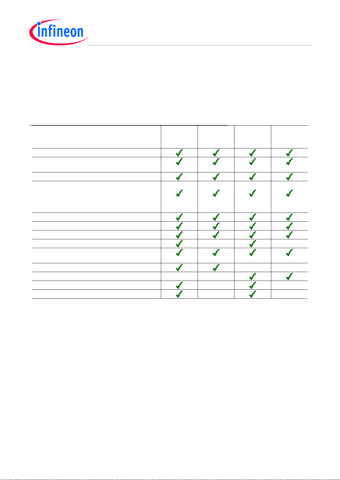
1.1 Key Features
Table 2 summarizes the features of the different assembly versions of the XMC4200 Platform2Go Series-V1.1.
Table 2 Kit Features of Assembly Versions
Feature
XMC4200
Platform2Go
3.3V
XMC4200
Platform2Go
3.3V Lite
XMC4200
Platform2Go
5V
XMC4200
Platform2Go
5V Lite
XMC4200 Microcontroller
On-board Debug Probe with USB interface
supporting SWD + SWO
Virtual COM Port via Debug Probe
1 x User Push-Button and
1 x User LED and
1 x Reset Push-Button
1 x Potentiometer
Voltage Regulator 5 V -> 3.3 V
USB (Micro USB Plug)
12 MHz Crystal
32.768 kHz RTC Crystal
Arduino compatible connector 3.3 V / 5 V Arduino
shields
0 Ohm Bridges Array for 3.3 V Arduino shields
Voltage level shifter for 5 V Arduino
D-Sub Connector
CAN Transceiver
Page 8
XMC4200 Platform2Go Series-V1
Hardware Description
Board Users Manual 8 Revision 2019-08-30
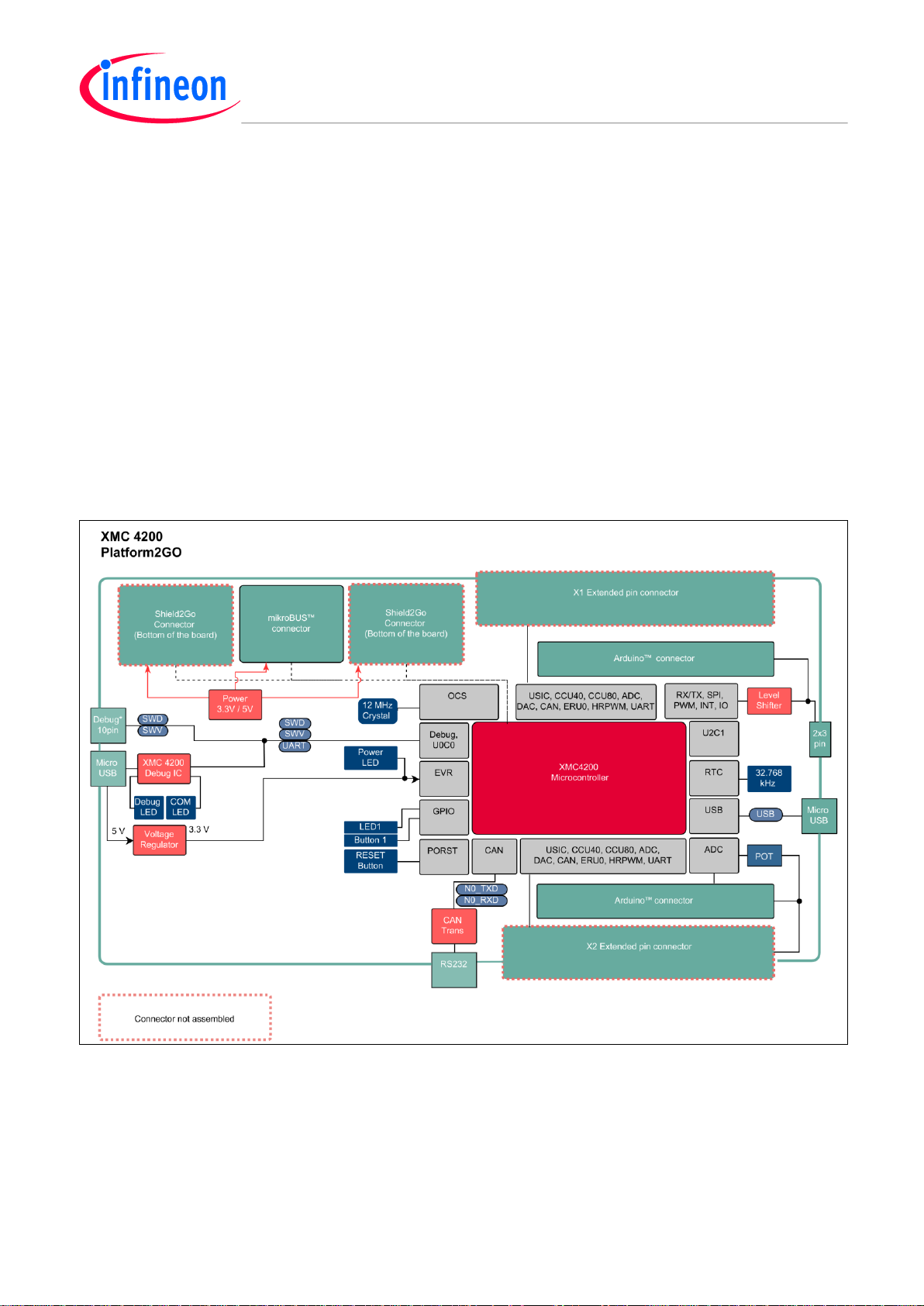
1.2 Block Diagram
The block diagram in Figure 1 shows the main components of the XMC4200 Platform2Go Series-V1.1 and their
interconnections. There are following main building blocks:
XMC4200 ontroller in a LQFP64 package
On-board USB debug probe based on XMC4200 for SWD, SWV and Virtual COM Port support
Two 40-pin header X1 and X2
Connection Header for Arduino
MikroBUS
TM
connector
Two Infineon Shield2Go connectors (at the bottom of the board)
Potentiometer (10kOhm)
On-board power generation
User Push-Button, User LED, Reset Push-Button
Micro-AB USB Plug
CAN Transceiver connected to 9-position D-Sub connector RS232
Figure 1 Block Diagram of the XMC4200 Platform2Go Series-V1.1
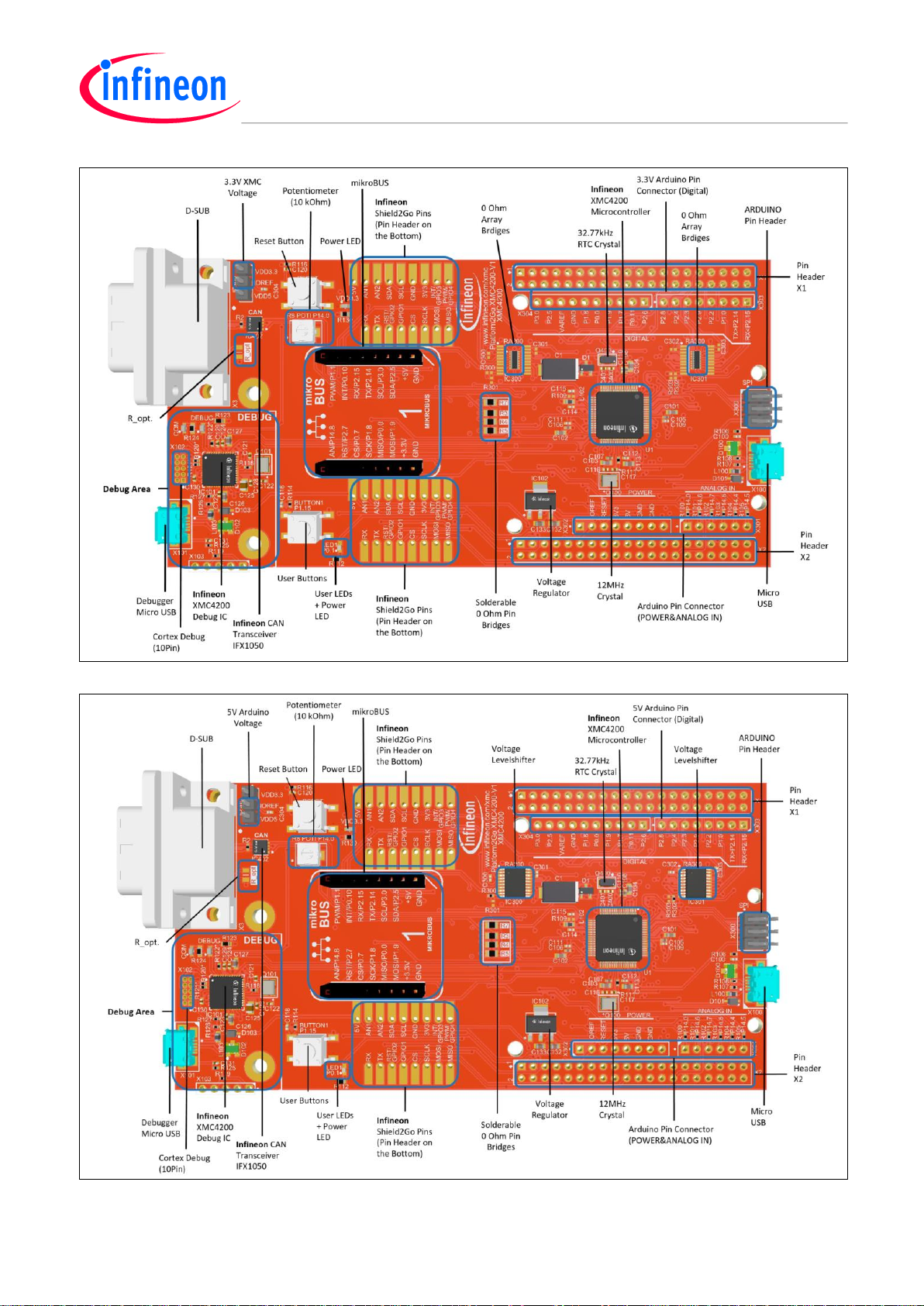
2 Hardware Description
The following chapters give a detailed description of the board hardware and how it can be used. The different
assembly versions of the kits series are shown in Figure 2, Figure 3, Figure 4 and Figure 5.
Page 9
XMC4200 Platform2Go Series-V1
Hardware Description
Board Users Manual 9 Revision 2019-08-30
Figure 2 XMC4200 Platform2Go 3.3V
Figure 3 XMC4200 Platform2Go 5V
Page 10

XMC4200 Platform2Go Series-V1
Hardware Description
Board Users Manual 10 Revision 2019-08-30
Figure 4 XMC4200 Platform2Go 3.3V Lite
Figure 5 XMC4200 Platform2Go 5V Lite
Page 11

XMC4200 Platform2Go Series-V1
Hardware Description
Board Users Manual 11 Revision 2019-08-30
2.1 Power Supply
The XMC4200 Platform2Go Series-V1.1 must be supplied by an external 5 Volt DC power supply connected to
any of the micro USB plugs (X100, X101). The green Power LED (VDD3.3) indicates the presence of the
generated 3.3 V supply voltage.
On-board reverse current protection diodes will ensure safe operation in case power is provided through both
USB plugs at the same time. These protection diodes allows to use the on-board debug probe connected with a
PC/Notebook via X101 and a second host PC/Laptop connected with the XMC4200 via X100.
If the board is powered via a USB plug, it’s not recommended to apply an additional 5 Volt power supply to one
of the 5 Volt power pins (VDD5, 5 V) on the pin headers X1 or X2 or the Arduino Power header, because there is
no protection against reverse current into the external power supply. These power pins can be used to power an
external circuit. But care must be taken not to draw more current than USB can deliver. A PC as USB host typically
can deliver up to 500 mA current. If higher currents are required and in order to avoid damages on the USB host
the use of an external USB power supply unit which is able to deliver higher currents than 500 mA is strongly
recommended.
Figure 6 Power Supply Concept
Page 12

XMC4200 Platform2Go Series-V1
Hardware Description
Board Users Manual 12 Revision 2019-08-30
2.2 Pin Header X1 and X2
The pin headers X1 and X2 can be used to extend the evaluation board or to perform measurements on the
XMC4200. Figure 7 shows the available GPIOs / signals at these pin headers. The pin table is also printed onto
the bottom side of the PCB in bottom view.
Pin Header X2
Pin Header X1
GND 2 1
P0.7
CS_MB
RESET#
2 1 GND
RST/GPIO2_2GO_1
P0.8 4 3
NC
UART_RX
P2.15
4 3 P2.14
UART_TX
NC 6 5
NC
NC 6 5
NC
NC 8 7
P0.11
PWM3 SPI_CS.PWM_4
P1.7
8 7 NC
NC
10 9 P0.5
INT/GPIO3_2GO_1
SPI_MOSI/PWM_5
P1.9
10 9 P1.8
SPI_CLK
RST/GPIO2_2GO_2
P0.6
12
11
P0.3
INT/GPIO3_2GO_2
PWM_MB
P1.1
12
11
P1.0
INT_0
GPIO1_S2GO_1
P0.4
14
13
P0.1
LED1 QSPI_IO2
P1.3
14
13
P1.2
PWM/GPIO4_2GO_1
CS_2GO_1
P0.2
16
15
P0.10
INT_MB QSPI_IO0
P1.5
16
15
P1.4
PC_TXD
SPI_MISO
P0.0
18
17
NC
NC
18
17
NC CS_2GO_2
P0.9
20
19
P3.0
SCL, ADC_5
NC
20
19
NC
NC
22
21
P14.14
AN2_2GO BUTTON1
P1.15*
22
21
NC
SDA, ADC_4,
AN1_2GO
P14.4
24
23
NC
NC
24
23
NC
NC
26
25
P14.6
ADC_1
NC
26
25
ADC_2
P14.7
28
27
NC
RST_MB
P2.7
28
27
P2.6
IO_2
SCL, ADC_5,
AN2_2GO
P14.5
30
29
NC
GPIO1_2GO_2
P2.1
30
29
P2.0*
CAN_TX
CAN_RX
P14.3*
32
31
NC
PWM_1
P2.3
32
31
P2.2
INT_1, PWM_0
ADC0/Potentiometer
P14.0
34
33
P14.8
AN_MB/DAC0
SDA, ADC_4
P2.5
34
33
P2.4
PWM_2
AN1_2GO/DAC1
P14.9
36
35
HIB_IO_0
IO_0
P2.9
36
35
P2.8
IO_1
VARREF
38
37
NC
NC
38
37
NC
VDD3.3
40
39
#VBAT
VDD5
40
39
VDD3.3
(Top View)
Figure 7 Signal mapping of the pin headers X1 and X2
*Note: These pins have solderable 0 Ohm (0805) resistor bridges. See section 2.4 and Table 3.
Page 13

XMC4200 Platform2Go Series-V1
Hardware Description
Board Users Manual 13 Revision 2019-08-30
2.3 Pin Header for Microbus and Shield2Go Connector 1 and 2
The pin header for Microbus and Shield2Go Connector 1 and 2 can be used to extend the evaluation board or to
perform measurements on the XMC4200. Figure 8 shows the available signals at these pin headers. The
Shield2Go pin header is mounted on the bottom. The pin table is also printed onto the top and bottom side of
the PCB in each view.
Shield2Go Connector 1 (bottom)
Shield2Go Connector 2(bottom)
1
VDD5
5V
1
VDD5
5V
2
P14.4
AN1
RX
P2.14
10
2
P14.9
AN1
RX
P2.15
10
3 P14.14
AN2
TX
P2.15
11
3
P14.5
AN2
TX
P2.14
11 4 P2.5
SDA
RST/GPIO2
P0.8
12
4
P2.5
SDA
RST/GPIO2
P0.6
12
5 P3.0
SCL
GPIO1
P0.4
13
5
P3.0
SCL
GPIO1
P2.1
13
6 GND
GND
CS
P0.2*
14
6
GND
GND
CS
P0.9*
14
7 VDD3.3
3V3
SCLK
P1.8*
15
7
VDD3.3
3V3
SLCK
P1.8*
15 8 P0.5
INT/GPIO3
MOSI
P1.9*
16
8
P0.3
INT/GPIO3
MOSI
P1.9*
16
9
P1.2
PWM/GIO4
MISO
P0.0*
17
9
P1.3
PWM/GPIO4
MISO
P0.0*
17
(Bottom View)
(Bottom View)
Microbus Connector
1
P14.8
AN
PWM
P1.1
16
*Note:
The SPI channels MOSI MISO and SLCK
are connected with both shields and the
microbus.
Each of the three mentioned connectors
has an own CS (Chipselect) channel.
2
P2.7
RST
INT
P0.10
15
3
P0.7*
CS
RX
P2.15
14
4
P1.8*
SCK
TX
P2.14
13
5
P0.0*
MISO
SCL
P3.0
12
6
P1.9*
MOSI
SDA
P2.5
11
7
VDD3.3
3.3V
5V
VDD5
10
8
GND
GND
GND
GND
9
(Top View)
Figure 8 Signal mapping of the pin headers for Microbus and Shield2Go Connector 1 and 2
Page 14

XMC4200 Platform2Go Series-V1
Hardware Description
Board Users Manual 14 Revision 2019-08-30
2.4 Solderable 0 Ohm Pin Bridges
The 0 Ohm (0805) pin bridges enable/disable the signal pins in Table 3 (enabled by default).
To disable the signals, their resistor has to be removed. The XMC4200 pins are then usable for other usages.
Table 3 Signal mapping of the 0 Ohm Pin Bridges
Resistor
XMC Pin
Signal
R3
P2.0
CAN_TX
R4
P14.3
CAN_RX
R5
P1.15
BUTTON1
R7
P14.0
Potentiometer
R112
P0.1
LED1
Page 15

XMC4200 Platform2Go Series-V1
Hardware Description
Board Users Manual 15 Revision 2019-08-30
2.5 Arduino Compatible Connector
The mapping of GPIOs and XMC pin functions to Arduino compatible functions can be found in Figure 9. The
Arduino compatible connector supports
SPI interface (SPI_xxx)
I2C interface (I2C_xxx)
UART interface (UART_xxx)
PWM signal outputs (PWM0-3)
ADC input (ADC0-5)
Interrupt input (INT0-1)
Figure 9 Mapping of Arduino Functions to XMC Pin Functions
The XMC4200 Platform2Go 5V features bi-directional voltage level shifter and therefor supports 5 V Arduino
shields. Jumper JP300 (IOREF) determines whether the Arduino shield is driven with 5 V or 3.3 V.
Analog input signals ADC0-5 are limited to 3.3 V input voltage. Primarily ADC0 to ADC3 should be used as analog
input, because there is no additional circuit connected to these pins, whereas ADC4 and ADC5 have additional
circuitry and require an input signal with lower input impedance. ADC0 is also connected to the Potentiometer for
a variable value of the analog input (optional see Table 5).
Note: Parallel operation of I2C and ADC4 / ADC5 is not possible, because they share the same Arduino pins.
Page 16

XMC4200 Platform2Go Series-V1
Hardware Description
Board Users Manual 16 Revision 2019-08-30
2.6 User Push Buttons, Potentiometer and User LEDs
The XMC4200 Platform2Go Series-V1.1 provides one user push button, one LED and one Potentiometer. The
port pins used can be found in Table 4 and Table 5.
Table 4 XMC4200 Pin Mapping for User LEDs
LED
XMC Pin
Resistor
LED1*
P0.1
R112 (680 Ohm)
Table 5 XMC4200 Pin Mapping for User Push Buttons and Potentiometer
Button
XMC Pin
Resistor
BUTTON1*
P1.15
R5
Potentiometer*
P14.0
R7
*Note: The push button, the potentiometer and the LED can be disabled by removing their designator.
Also see Table 3.
Debugging and UART-to-USB Communication
The XMC4200 Platform2Go Series-V1.1 supports debugging via 2 different channels:
On-board debug probe
10-pin Cortex™ Debug Connector (not assembled)
2.7 On-board Debug Probe
The on-board debug probe supports Serial Wire Debug (SWD) and UART communication. Both require the
installation of Segger’s J-Link Driver which is part of the DAVE™ installation. DAVE™ is a highly efficient
development platform for the XMC microcontroller families to simplify and shorten SW development. It can be
downloaded at www.infineon.com/dave. The latest Segger J-Link Driver can be downloaded at
http://www.segger.com/jlink-software.html. Table 6 shows the pin assignment of the XMC4200 used for
debugging and UART communication.
2.8 UART Communication for XMC4200
Table 6 XMC4200 Pins Mapping for Debugging and UART-Communication
Pin Function
Input/Output
XMC Pin
Data pin for Debugging via SWD
I/O
TMS
Clock pin for Debugging via SWD
O
TCK
Transmit pin for UART communication (PC_RX)
O
XMC4200 Debugger
P1.5 (TXD_U0C0.DOUT0)
Receive pin for UART communication (PC_TX)
I
XMC4200 Debugger
P1.4 (RXD_U0C0.DX0B)
Transmit pin for UART(UART_RX)
O
XMC4200
P2.15(RXD_U1C0.DX0C)
Receive pin for UART(UART_TX)
I
XMC4200
P2.14(TXD_U1C0.DOUT0)
2.9 Cortex™ Debug Connector (10-pin)
The 10-pin Cortex™ Debug Connector supports Serial Wire Debug (SWD) and Serial Wire Viewer (SWV). The
pin assignment of the Cortex™ Debug Connector is shown in Table 6.
Page 17

XMC4200 Platform2Go Series-V1
Hardware Description
Board Users Manual 17 Revision 2019-08-30
Table 7 Pin Assignment of the Cortex™ Debug Connector (X102)
Pin No.
Signal Name
Description
1
VCC
+3.3 V
2
TMS
Serial Wire Data I/O
3
GND
Ground
4
TCK
Serial Wire Clock
5
GND
Ground
6
SWV
Serial Wire Viewer (Trace Data Out)
7
NC
Not connected
8
NC
Not connected
9
GND_Detect
Ground detect
10
RESET
Rest (active low)
2.10 Reset
The reset pin (PORST#) of the XMC4200 is a bi-directional pin in open drain mode. An internal pull-up resistor
keeps the PORST# pin high during normal operation. A low level at this pin will force a hardware reset. In case of
a MCU internal reset the PORST# pin will drive a low signal.
A reset signal can be issued by
the on-board Reset Button (“RESET”)
the on-board debug probe (IC101.47)
the external debugger connected to the 10-pin Cortex™ Debug probe connector (X102)
the Arduino Power Header (X302.3, “RESET#”)
the pin header X1 (X1.2, “RESET#”)
An XMC™ internal circuit always ensures a save Power-on-Reset. XMC™ does not require any additional external
components to generate a reset signal during power-up.
2.11 CAN Transceiver
The XMC4200 Platform2Go provides a CAN interface via X3, a D-Sub DE-9, and the X1 and X2 connector.
Infineon’s high speed CAN transceiver (IFX1051LE) for industrial applications supports 3.3V I/O logic and is
suitable for 12 V and 24 V bus systems with an excellent EMC performance. The CAN bus (signals CANH, CANL)
are terminated by a 120 Ohm resistor and can provide 5V if R_opt is assembled with a 0 Ohm 0805 resistor (not
assembled by default). The other CAN bus (CAN_TX, CAN_RX) is not terminated by a 120 Ohm and needs to be
terminated externally. To use the CAN_TX/RX pins otherwise see also Table 3.
Table 8 CAN Signals and XMC4200 Pin Mapping
Signal
Name
Pin No. at Pin Header
XMC Pin, XMC Function
CANH
X3.7
-
CANL
X3.2
-
CAN_TX
X2.34
P2.0, CAN_TX
CAN_RX
X1.29
P14.0, CAN_RX
GND
X3.3, X3.6
-
VDD5
X3.9
-
Page 18

XMC4200 Platform2Go Series-V1
Production Data
Board Users Manual 18 Revision 2019-08-30
2.12 Boot Option
During power-on-reset the XMC4200 latches the signal level at the pins TMS and TCK. Based on the logic levels
latched at these pins after reset the XMC4200 starts booting in different modes. TMS and TCK pins are used for
debugging and by default program execution is always starting from on-chip flash (normal mode).
The XMC4200 Platform2Go Series-V1.1 does not support the selection of the boot options by switches directly.
In case of no external debug probe is used the boot mode can be influenced by applying 1 kOhm pull-up- or pulldown resistors to TMS and TCK pins. These pins are available at the 10-pin debug connector X102.
Table 9 Boot Mode Selection with external Pull Resistors
Logic Level at TMS
during Reset
Logic Level at TCK
during Reset
Boot Mode
High
Low
Normal Mode (boot from on-chip flash) (DEFAULT)
Low
Low
ASC BSL Mode (boot from UART)
High
High
BMI Customized Boot Mode
Low
High
CAN BSL Mode (boot from CAN)
3 Production Data
This chapter covers schematics, board dimensions, component placement and the list of material.
3.1 Schematics
In the following figures shows the schematics of the XMC4200 Platform2Go Series-V1.1 in.
Page 19

XMC4200 Platform2Go Series-V1
Production Data
Board Users Manual 19 Revision 2019-08-30
Figure 10 Connectors Schematic: Pin header, Pin Bridges, Level Shifter, Microbus, Shield2Go
Connector, Arduino Level Jumper
1
1
2
2
3
3
4
4
5
5
6
6
7
7
8
8
D D
C C
B B
A A
2 5
30.09.2019 14:47:33Date:
Sheet of
Time:
© Infineon Technologies AG 2019. All Rights Reserved.
Author:
IFAG DES TCP EDS
Am Campeon 1-15, Munich
V1.1
Title
Size: Rev.
A3
Rel.
Draft
Variant
Platform2GO XMC4200-V1.1
Approved
Open
Status
SVN Revision: da75247807cb30a8ab86d75f81b360f14d63d5c9
J.Fischer
2 5
Connectors.SchDoc
Pinheader/Arduinopinheader
Arduino Level Shifter
Arduino Level Jumper
Arduino Level Shifter Bridges
IO_0
IO_1
PWM_1
PWM_2
INT_0
INT_1, PWM_0
UART_TX
UART_RX
ADC_2
ARDUINO Compatible Connectors
GND
GND5V3V3
RESET
NC
IO_1
PWM_2
PWM_1
IO_0
INT_1, PWM_0
INT_0
UART_TX
UART_RX
IO_1
PWM_2
PWM_1
IO_0
INT_0
UART_TX
UART_RX
IO_1
PWM_2
PWM_1
IO_0
INT_1, PWM_0
INT_0
UART_TX
UART_RX
IO_1
PWM_2
PWM_1
IO_0
INT_1, PWM_0
INT_0
UART_TX
UART_RX
VDD3.3
VDD3.3
VDD5
GND
VDD3.3
GND
GND
GND
GND
GND
GND
R100
R101
R102
R103
R104
R105
C300 100nF
C301 100nF
C302 100nF
C303 100nF
R300
10k
R302
10k
R301
0R
R303
0R
no ass.
no ass.
C304
100nF
VCCA
2
GND
11
OE_N10A11A23A34A45A56A67A78A8
9
B120B218B317B416B515B614B713B8
12
VCCB
19
IC300
TXS0108EPWR
SCL, ADC_5
SDA, ADC_4
SPI_CLK
SPI_MISO
SPI_MOSI
SPI_CS
SCL, ADC_5
SDA, ADC_4
SPI_CLK
SPI_MISO
SPI_MOSI
SPI_CS
IOREF
VDD3.3
VDD3.3
GND
VCCA
2
GND
11
OE_N10A11A23A34A45A56A67A78A8
9
B120B218B317B416B515B614B713B8
12
VCCB
19
IC301
TXS0108EPWR
P2.14*P2.14
P2.15
VDD3.3
IOREF
GND
VDD3.3
VDD3.3
GND
VDD5
GND
UART_RX
UART_TX
ADC_3/AN_MB/DAC0
AN
RSTCSSCK
MISO
MOSI
3.3V
GND
PWM
INT
RX
TX
SCL
SDA
5V
GND
MIKROBUS
PWM_MB/P1.1
SPI_MOSI
SPI_MISO
SPI_CLK
CS_MB/P0.7
RST_MB/P2.7
INT_MB/P0.10
Microbus Connector
SCL, ADC_5
SDA, ADC_4
GND
SCL, ADC_5
SDA, ADC_4
UART_TX
UART_RX
P2.15
SPI_CLK
SPI_MISO
SPI_MOSI
PWM/GPIO4_2GO_1
CS_2GO_1/P0.2
INT/GPIO3_2GO_1
RST/GPIO2_2GO_2
VDD3.3
VDD5
123456789 17
16151413121110
5V
AN1
AN2
SDA
SCL
GND
3V3
INT/GPIO3
PWM/GPIO4
RX
TX
RST/GPIO2
GPIO1
CS
SCLK
MOSI
MISO
PASSIVE
S2G-1P-1
Shield2Go-S2G-1P
123456789 17
16151413121110
5V
AN1
AN2
SDA
SCL
GND
3V3
INT/GPIO3
PWM/GPIO4
RX
TX
RST/GPIO2
GPIO1
CS
SCLK
MOSI
MISO
PASSIVE
S2G-1P-2
Shield2Go-S2G-1P
VDD5
GND
VDD3.3
P2.15
P2.14
PWM/GPIO4_2GO_2
UART_TX
UART_RX
SPI_CLK
SPI_MISO
SPI_MOSI
CS_2GO_2/P0.9
GPIO1_2GO_2/P2.1
RST/GPIO2_2GO_1
SCL, ADC_5
SDA, ADC_4
INT/GPIO3_2GO_2
Shield2Go Connector
INT_1, PWM_0
SCL, ADC_5
SDA, ADC_4
SPI_CLK
SPI_MISO
SPI_MOSI
SPI_CS
PWM_3
IO_2
SCL, ADC_5
SDA, ADC_4
SPI_CLK
SPI_MISO
SPI_MOSI
SPI_CS
PWM_3
IO_2
P2.15*
1234567891011131517192123252729
31
1214161820222426283032
333537
39
343638
40
X2
M20-6102045
123
JP300
TSW-103-05-L-S
IOREF
1 2
3 4
5 6
X300
GND
VDD5
RESET#
1234567
8
X302
IOREF
RESET#
VDD3.3
VDD5
GND
12345
6
X301
1234567
8
X303
P2.15*
P2.14*
1102938475
6
X304
GND
VAREF
SPI_CLK
SPI_MISO
SPI_MOSI
SPI_CS
PWM_3
IO_2
SCL, ADC_5
SDA, ADC_4
GND
AREF
SDA, ADC_4, AN1_2GO
SCL, ADC_5, AN2_2GO
1234567891011131517192123252729
31
1214161820222426283032
333537
39
343638
40
X1
M20-6102045
Shields share reset pin P0.10
R3 0R
R4 0R
CAN_TX
CAN_RX
GPIO1_2GO_1/P3.0
R5 0R
BUTTON1
BUTTON1
P0.0
P0.0
P0.0 P0.0*
P0.0 P0.0*
P0.0*
P0.2
P0.3
P0.5
P0.7
P0.6
P0.8
P0.9
P0.10
P3.0
P3.0
P3.0
P3.0 P3.0*
P3.0 P3.0*
P3.0*
P3.0*
P1.1
P0.0*
P1.3
CAN_TX/P2.0
P2.5
P2.5
P2.5
P2.5
P2.5 P2.5*
P2.5*
P2.5*
P2.5*
P1.7*
P1.7*
P1.7*P1.7
P1.7
P1.8
P1.8
P1.8
P1.8
P1.8 P1.8*
P1.8*
P1.8*
P1.8*
P1.9
P1.9
P1.9
P0.0
P1.9
P1.9 P1.9*
P1.9*
P1.9*
P1.9*
P2.1P2.2
P2.2 P2.2*
P2.2*
P2.2*
P2.3
P2.3
P2.3*
P2.3*
P2.4
P2.4 P2.4*
P2.3*
P2.4*
P2.4*
P1.0
P1.0 P1.0*
P1.0*
P1.0*
P1.15
P2.8
P2.8 P2.8*
P2.8*
P2.8*
P2.9
P2.9
P2.9*
P2.9*
P2.9*
P2.14
P2.15
P2.14*
P2.15*
P14.0
ADC_1/CAN_RX/P14.3
P14.6
P14.3
CAN_RX/P14.3
P14.7
P14.8
P14.4
P14.5
AN2_2GO
P14.4
P14.14
P14.9
P14.5
AN1_2GO/DAC1
P14.8
P2.14
P2.15
Pin Bridges
VDD3.3
SPI_CS
SPI_MOSI
ADC0/Potentiometer/P14.0
1234567
8 9
10
111213
14
15
16
RA200A
0R
1234567
8 9
10
111213
14
15
16
RA300A
0R
P0.11 P0.11*
P0.11*
P1.2
P2.0
P2.6 P2.6*
P2.6*
P2.7
ADC_3/AN_MB/DAC0
P0.4
P0.8
GND
P0.7
P0.11
P0.1
P0.2
P0.3
P0.4
P0.5
P0.6
P0.9
P0.10
P0.0
P3.0
P14.0
P14.3
P14.5
P14.7
P14.8
P14.9
P14.14
VAREF
HIB_IO_0
#VBAT
P2.14P2.15
P1.0P1.1
P1.2P1.3
P1.4P1.5
P1.7
P1.8P1.9
P2.0P2.1
P2.2P2.3
P2.4P2.5
P2.6P2.7
P2.8P2.9
RESET#
VDD5 VDD3.3
UART_TX
UART_RX
GND
PWM_MB/P1.1
PWM/GPIO4_2GO_2
PC_RXD PC_TXD
SDA, ADC_4
PWM_1
PWM_2
IO_0
INT_1, PWM_0
GPIO1_2GO_2/P2.1
RST_MB/P2.7
IO_1
IO_2
CAN_TX/P2.0
SPI_CLK
INT_0
PWM/GPIO4_2GO_1
SPI_MISO
PWM_3
RST/GPIO2_2GO_1
GPIO1_S2GO_1
P0.1/LED1
INT/GPIO3_2GO_2
INT/GPIO3_2GO_1
RST/GPIO2_2GO_2
INT_MB/P0.10
CS_MB/P0.7
CS_2GO_1/P0.2
CS_2GO_2/P0.9
AN_MB/DAC0
CAN_RX/P14.3
ADC_1
ADC_2
AN2_2GO
ADC0/Potentiometer/P14.0
AN1_2GO/DAC1
P14.6
SCL, ADC_5
PWM_3PWM_3
P0.11 P0.11*
IO_2
IO_2
P2.6 P2.6*
P14.4
BUTTON1
SDA, ADC_4, AN1_2GO
SDA, ADC_4, AN1_2GO
SCL, ADC_5, AN2_2GO
SCL, ADC_5, AN2_2GO
P1.15
P2.14
PIC30001
PIC30002
COC300
PIC30101
PIC30102
COC301
PIC30201
PIC30202
COC302
PIC30301
PIC30302
COC303
PIC30401
PIC30402
COC304
PIIC30001
PIIC30002
PIIC30003
PIIC30004
PIIC30005
PIIC30006
PIIC30007
PIIC30008
PIIC30009
PIIC300010
PIIC300011
PIIC300012
PIIC300013
PIIC300014
PIIC300015
PIIC300016
PIIC300017
PIIC300018
PIIC300019
PIIC300020
COIC300
PIIC30101
PIIC30102
PIIC30103
PIIC30104
PIIC30105
PIIC30106
PIIC30107
PIIC30108
PIIC30109
PIIC301010
PIIC301011
PIIC301012
PIIC301013
PIIC301014
PIIC301015
PIIC301016
PIIC301017
PIIC301018
PIIC301019
PIIC301020
COIC301
PIJP30001
PIJP30002
PIJP30003
COJP300
PIMIKROBUS01
PIMIKROBUS02
PIMIKROBUS03
PIMIKROBUS04
PIMIKROBUS05
PIMIKROBUS06
PIMIKROBUS07
PIMIKROBUS08
PIMIKROBUS09
PIMIKROBUS010
PIMIKROBUS011
PIMIKROBUS012
PIMIKROBUS013
PIMIKROBUS014
PIMIKROBUS015
PIMIKROBUS016
COMIKROBUS
PIR301
PIR302
COR3
PIR401
PIR402
COR4
PIR501
PIR502
COR5
PIR10001
PIR10002
COR100
PIR10101
PIR10102
COR101
PIR10201
PIR10202
COR102
PIR10301
PIR10302
COR103
PIR10401
PIR10402
COR104
PIR10501
PIR10502
COR105
PIR30001
PIR30002
COR300
PIR30101
PIR30102
COR301
PIR30201
PIR30202
COR302
PIR30301
PIR30302
COR303
PIRA20001
PIRA20002
PIRA20003
PIRA20004
PIRA20005
PIRA20006
PIRA20007
PIRA20008
PIRA20009
PIRA200010
PIRA200011
PIRA200012
PIRA200013
PIRA200014
PIRA200015
PIRA200016
CORA200A
PIRA30001
PIRA30002
PIRA30003
PIRA30004
PIRA30005
PIRA30006
PIRA30007
PIRA30008
PIRA30009
PIRA300010
PIRA300011
PIRA300012
PIRA300013
PIRA300014
PIRA300015
PIRA300016
CORA300A
PIS2G01P0101
PIS2G01P0102
PIS2G01P0103
PIS2G01P0104
PIS2G01P0105
PIS2G01P0106
PIS2G01P0107
PIS2G01P0108
PIS2G01P0109
PIS2G01P01010
PIS2G01P01011
PIS2G01P01012
PIS2G01P01013
PIS2G01P01014
PIS2G01P01015
PIS2G01P01016
PIS2G01P01017
COS2G01P01
PIS2G01P0201
PIS2G01P0202
PIS2G01P0203
PIS2G01P0204
PIS2G01P0205
PIS2G01P0206
PIS2G01P0207
PIS2G01P0208
PIS2G01P0209
PIS2G01P02010
PIS2G01P02011
PIS2G01P02012
PIS2G01P02013
PIS2G01P02014
PIS2G01P02015
PIS2G01P02016
PIS2G01P02017
COS2G01P02
PIX101
PIX102
PIX103
PIX104
PIX105
PIX106
PIX107
PIX108
PIX109
PIX1010
PIX1011
PIX1012
PIX1013
PIX1014
PIX1015
PIX1016
PIX1017
PIX1018
PIX1019
PIX1020
PIX1021
PIX1022
PIX1023
PIX1024
PIX1025
PIX1026
PIX1027
PIX1028
PIX1029
PIX1030
PIX1031
PIX1032
PIX1033
PIX1034
PIX1035
PIX1036
PIX1037
PIX1038
PIX1039
PIX1040
COX1
PIX201
PIX202
PIX203
PIX204
PIX205
PIX206
PIX207
PIX208
PIX209
PIX2010
PIX2011
PIX2012
PIX2013
PIX2014
PIX2015
PIX2016
PIX2017
PIX2018
PIX2019
PIX2020
PIX2021
PIX2022
PIX2023
PIX2024
PIX2025
PIX2026
PIX2027
PIX2028
PIX2029
PIX2030
PIX2031
PIX2032
PIX2033
PIX2034
PIX2035
PIX2036
PIX2037
PIX2038
PIX2039
PIX2040
COX2
PIX30001
PIX30002
PIX30003
PIX30004
PIX30005
PIX30006
COX300
PIX30101
PIX30102
PIX30103
PIX30104
PIX30105
PIX30106
COX301
PIX30201
PIX30202
PIX30203
PIX30204
PIX30205
PIX30206
PIX30207
PIX30208
COX302
PIX30301
PIX30302
PIX30303
PIX30304
PIX30305
PIX30306
PIX30307
PIX30308
COX303
PIX30401
PIX30402
PIX30403
PIX30404
PIX30405
PIX30406
PIX30407
PIX30408
PIX30409
PIX304010
COX304
PIX2039
NL#VBAT
PIR501
NLBUTTON1
PIR401
NLCAN0RX
PIR301
NLCAN0TX
PIC30001
PIC30101
PIC30201
PIC30301
PIC30401
PIIC300011
PIIC301011
PIMIKROBUS08
PIMIKROBUS09
PIR30101
PIR30301
PIS2G01P0106
PIS2G01P0206
PIX101
PIX202
PIX30006
PIX30206
PIX30207
PIX30407
NLGND
PIX2035
NLHIB0IO00
PIC30102
PIC30302
PIC30402
PIIC300019
PIIC301019
PIJP30002
PIX30202
NLIOREF
PIIC300010
PIR30002
PIR30102
PIIC301010
PIR30202
PIR30302
PIR10002
PIX30101
PIR10102
PIX30102
PIR10202
PIX30103
PIR10302
PIX30104
PIX105
PIX106
PIX107
PIX1017
PIX1018
PIX1019
PIX1020
PIX1021
PIX1023
PIX1024
PIX1025
PIX1026
PIX1037
PIX1038
PIX203
PIX205
PIX206
PIX208
PIX2010
PIX2017
PIX2022
PIX2023
PIX2026
PIX2027
PIX2029
PIX2031
PIX2037
PIX30201
PIX30208
PIIC30001
PIMIKROBUS05
PIRA20001
PIS2G01P01017
PIS2G01P02017
PIX2018
NLP000
PIIC300020
PIRA200016
PIX30001
PIX30405
NLP0000
PIX2013
PIMIKROBUS015
PIX2015
NLP001
NLP0010
PIS2G01P01014
PIX2016
NLP002
PIS2G01P0208
PIX2011
NLP003
PIS2G01P01013
PIX2014
NLP004
PIS2G01P0108
PIX209
NLP005
PIS2G01P02012
PIX2012
NLP006
PIMIKROBUS03
PIX201
NLP007
PIS2G01P01012
PIX204
NLP008
PIS2G01P02014
PIX2020
NLP009
PIIC30003
PIRA20002
PIX207
NLP0011
PIIC300018
PIRA200015
PIX30402
NLP00110
PIIC30105
PIRA30004
PIX1011
NLP100
PIIC301016
PIRA300013
PIX30303
NLP1000
PIMIKROBUS016
PIX1012
NLP101
PIS2G01P0109
PIX1013
NLP102
PIS2G01P0209
PIX1014
NLP103
PIX1015
NLP104
PIX1016
NLP105
PIIC30006
PIRA20005
PIX108
NLP107
PIIC300015
PIRA200012
PIX30403
NLP1070
PIIC30007
PIMIKROBUS04
PIRA20006
PIS2G01P01015
PIS2G01P02015
PIX109
NLP108
PIIC300014
PIRA200011
PIX30003
PIX30406
NLP1080
PIIC30008
PIMIKROBUS06
PIRA20007
PIS2G01P01016
PIS2G01P02016
PIX1010
NLP109
PIIC300013
PIRA200010
PIX30004
PIX30404
NLP1090
PIR502
PIX1022
NLP1015
PIR302
PIX1029
NLP200
PIS2G01P02013
PIX1030
NLP201
PIIC30101
PIRA30001
PIX1031
NLP202
PIIC301020
PIRA300016
PIX30304
NLP2020
PIIC30103
PIRA30002
PIX1032
NLP203
PIIC301018
PIRA300015
PIX30306
NLP2030
PIIC30104
PIRA30003
PIX1033
NLP204
PIIC301017
PIRA300014
PIX30307
NLP2040
PIIC30005
PIMIKROBUS011
PIRA20004
PIS2G01P0104
PIS2G01P0204
PIX1034
NLP205
PIIC300016
PIR10402
PIRA200013
PIX30105
PIX30409
NLP2050
PIIC30009
PIRA20008
PIX1027
NLP206
PIIC300012
PIRA20009
PIX30401
NLP2060
PIMIKROBUS02
PIX1028
NLP207
PIIC30106
PIRA30005
PIX1035
NLP208
PIIC301015
PIRA300012
PIX30308
NLP2080
PIIC30107
PIRA30006
PIX1036
NLP209
PIIC301014
PIRA300011
PIX30305
NLP2090
PIIC30108
PIMIKROBUS013
PIRA30007
PIS2G01P01011
PIS2G01P02011
PIX103
NLP2014
PIIC301013
PIRA300010
PIX30302
NLP20140
PIIC30109
PIMIKROBUS014
PIRA30008
PIS2G01P01010
PIS2G01P02010
PIX104
NLP2015
PIIC301012
PIRA30009
PIX30301
NLP20150
PIIC30004
PIMIKROBUS012
PIRA20003
PIS2G01P0105
PIS2G01P0205
PIX2019
NLP300
PIIC300017
PIR10502
PIRA200014
PIX30106
PIX304010
NLP3000
PIR10001
PIX2034
NLP1400
PIR402
PIX2032
NLP1403
PIR10401
PIS2G01P0102
PIX2024
NLP1404
PIR10501
PIS2G01P0203
PIX2030
NLP1405
PIR10101
PIX2025
NLP1406
PIR10201
PIX2028
NLP1407
PIMIKROBUS01
PIR10301
PIX2033
NLP1408
PIS2G01P0202
PIX2036
NLP1409
PIS2G01P0103
PIX2021
NLP14014
PIX102
PIX30005
PIX30203
NLRESET#
PIX2038
PIX30408
NLVAREF
PIC30002
PIC30202
PIIC30002
PIIC30102
PIJP30001
PIMIKROBUS07
PIR30001
PIR30201
PIS2G01P0107
PIS2G01P0207
PIX1039
PIX2040
PIX30204
PIJP30003
PIMIKROBUS010
PIS2G01P0101
PIS2G01P0201
PIX1040
PIX30002
PIX30205
Page 20

XMC4200 Platform2Go Series-V1
Production Data
Board Users Manual 20 Revision 2019-08-30
Figure 11 XMC_4200_Debug Schematic: OBD Probe
1
1
2
2
3
3
4
4
5
5
6
6
7
7
8
8
D D
C C
B B
A A
5 5
30.09.2019 14:47:35Date:
Sheet of
Time:
© Infineon Technologies AG 2019. All Rights Reserved.
Author:
IFAG DES TCP EDS
Am Campeon 1-15, Munich
V1.1
Title
Size: Rev.
A3
Rel.
Draft
Variant
Platform2GO XMC4200-V1.1
Approved
Open
Status
SVN Revision:
da75247807cb30a8ab86d75f81b360f14d63d5c9
J.Fischer
5 5
XMC4200_Debug.SchDoc
VDDP5VDDC6VBAT
10
VSSA/VAGND
17
VDDA/VAREF
18
VSS
27
VDDP28VDDC
31
VDDP
41
VSS
49
USB_DM3USB_DP
4
HIB_IO_0
7
RTC_XTAL18RTC_XTAL29XTAL129XTAL2
30
PORST_N
32
TMS
33
TCK
34
IC101A
IFX_ XMC4200Q48K256ABXUMA1
P0.11P0.0
2
P14.711P14.612P14.513P14.414P14.315P14.0
16
P14.919P14.8
20
P2.521P2.422P2.323P2.224P2.125P2.026P1.535P1.436P1.337P1.238P1.139P1.0
40
P0.842P0.743P0.644P0.545P0.446P0.347P0.2
48
IC101B
IFX_ XMC4200Q48K256ABXUMA1
VDD3.3
GND
R118
510R
1 3
2 4
Q101
12MHz
GNDGND
12345
X103
TSW-105-07-L-S
GND
VDD3.3
WTMS
WTCK
DBGPRES#
R119
10k
VDD3.3
5 TH-Pads
2.54mm pitch
R120* 22R
R121* 22R
12345
MP1
MP2
MP3
MP4
MP5
MP6
X101
ZX62-AB-5PA(31)
GND
12
D103
BAS3010A-03W
R126
4.7k
R127
10k
L103 60R
GNDGND
VDD5
HIB_IO_0
HIB_IO_0
R125
1MEG
GND
C125
4.7uF
C127 10uF
GND
GND
VDD3.3
TCKCSSWV
R122* 510R
TXD
RESET#
SWV
SWV
TMS
TMS
TCK
TCK
CS
SPD
No RESET Pin
Level Shifter
JTAG
SWV
UART
DEBUG_LED
COM_LED
VDD3.3
C128 100nF
C129 100nF
C130 100nF
C123 100nF
C124 100nF
C131
100nF
C121
15pF
C122
15pF
C126 10uF
COM_LED
DEBUG_LED
XTAL1_42
XTAL2_42
XTAL1_42 XTAL2_42
On-board Debugger
LED Clock
GND
GND
R124
680R
R123
680R
WUSB_DP
WUSB_DM
WUSB_DP
WUSB_DM
Debug Micro-USB Connector
SCLKOUT-P1.1
DX0B-P1.4
DX0D-P0.0
DOUT0-P2.5
DX0A-P2.2
SPI Slave
TMS
TCK
TDI
TDO
MOSI
CLK_OUT
MISO
MISO
CS_IN
CLK_IN
MOSI
CS_OUT
SPI Master
RXD
UART
U0C0
U0C1
U1C1
DOUT0-P1.5
SELO0-P1.0
DX2A-P2.3
DX1A-P2.4
RXD
TXD
UART2 (DM2)
RXD
TXD
DX0A-P0.4
DOUT0-P0.5
U1C0
SWV
On-board Debugger Concept
TXACTIVE# GPIO-P0.6
RESET# RESET# GPIO-P0.3
DEBUG_LED# DEBUG_LED# GPIO-P0.2
AUX_LED#COM_LED# GPIO-P0.1
Cortex Debug
no ass.
GND
VDD3.3
DBGPRES#
TMS
TCK
SWV
1 293 475 6
8
10
X102
FTSH-105-01-L-D-K
WVDDC
Caps of XMC4200
RESET#
VDD3.3
VDD3.3
P1.5
P1.4
PC_RXD
PC_TXD
3
1
2
D102
PGB102ST23WR
1 2
DEBUG
Green
1 2
COM
Green
Not assembled.
PIC12101
PIC12102
COC121
PIC12201
PIC12202
COC122
PIC12301
PIC12302
COC123
PIC12401
PIC12402
COC124
PIC12501
PIC12502
COC125
PIC12601
PIC12602
COC126
PIC12701
PIC12702
COC127
PIC12801
PIC12802
COC128
PIC12901
PIC12902
COC129
PIC13001
PIC13002
COC130
PIC13101
PIC13102
COC131
PICOM01
PICOM02
COCOM
PID10201
PID10202
PID10203
COD102
PID10301
PID10302
COD103
PIDEBUG01
PIDEBUG02
CODEBUG
PIIC10103
PIIC10104
PIIC10105
PIIC10106
PIIC10107
PIIC10108
PIIC10109
PIIC101010
PIIC101017
PIIC101018
PIIC101027
PIIC101028
PIIC101029
PIIC101030
PIIC101031
PIIC101032
PIIC101033
PIIC101034
PIIC101041
PIIC101049
COIC101A
PIIC10101
PIIC10102
PIIC101011
PIIC101012
PIIC101013
PIIC101014
PIIC101015
PIIC101016
PIIC101019
PIIC101020
PIIC101021
PIIC101022
PIIC101023
PIIC101024
PIIC101025
PIIC101026
PIIC101035
PIIC101036
PIIC101037
PIIC101038
PIIC101039
PIIC101040
PIIC101042
PIIC101043
PIIC101044
PIIC101045
PIIC101046
PIIC101047
PIIC101048
COIC101B
PIL10301
PIL10302
COL103
PIQ10101
PIQ10102
PIQ10103
PIQ10104
COQ101
PIR11801
PIR11802
COR118
PIR11901
PIR11902
COR119
PIR120001
PIR120002
COR1200
PIR121001
PIR121002
COR1210
PIR122001
PIR122002
COR1220
PIR12301
PIR12302
COR123
PIR12401
PIR12402
COR124
PIR12501
PIR12502
COR125
PIR12601
PIR12602
COR126
PIR12701
PIR12702
COR127
PIX10101
PIX10102
PIX10103
PIX10104
PIX10105
PIX1010MP1
PIX1010MP2
PIX1010MP3
PIX1010MP4
PIX1010MP5
PIX1010MP6
COX101
PIX10201
PIX10202
PIX10203
PIX10204
PIX10205
PIX10206
PIX10207
PIX10208
PIX10209
PIX102010
COX102
PIX10301
PIX10302
PIX10303
PIX10304
PIX10305
COX103
PICOM01
PIIC10101
NLCOM0LED
PIIC101023
PIIC101040
NLCS
PIIC101032
PIR11901
PIX10209
PIX10304
NLDBGPRES#
PIDEBUG01
PIIC101048
NLDEBUG0LED
PIC12101
PIC12201
PIC12301
PIC12401
PIC12501
PIC12602
PIC12701
PIC12801
PIC12901
PIC13001
PIC13101
PID10203
PIIC101013
PIIC101015
PIIC101016
PIIC101017
PIIC101020
PIIC101027
PIIC101049
PIQ10102
PIQ10104
PIR12502
PIR12702
PIX10105
PIX10203
PIX10205
PIX10305
PIIC10107
PIR12601
PIR12701
NLHIB0IO00
PIC13102
PIR12501
PIX1010MP1
PIX1010MP2
PIX1010MP3
PIX1010MP4
PIX1010MP5
PIX1010MP6
PICOM02
PIR12401
PID10201
PIR121001
PIX10103
PID10202
PIR120001
PIX10102
PID10302
PIL10302
PIR12602
PIDEBUG02
PIR12301
PIIC10108
PIIC10109
PIIC101011
PIIC101012
PIIC101014
PIIC101019
PIIC101021
PIIC101025
PIIC101026
PIIC101030
PIR11802
PIIC101037
PIIC101038
PIIC101042
PIIC101043
PIIC101044
PIL10301
PIX10101
PIX10104
PIX10207
PIX10208
PIR122001
NLP104
PIIC101046
NLP105
PIIC101047
PIX102010
NLRESET#
PIIC10102
PIIC101024
PIX10206
NLSWV
PIIC101022
PIIC101039
PIX10204
NLTCK
PIIC101035
PIIC101036
PIX10202
NLTMS
PIIC101045
PIR122002
NLTXD
PIC12302
PIC12402
PIC12502
PIC12601
PIC12702
PIC12802
PIC12902
PIC13002
PIIC10105
PIIC101010
PIIC101018
PIIC101028
PIIC101041
PIR11902
PIR12302
PIR12402
PIX10201
PIX10301
PID10301
PIIC101034
PIX10302
NLWTCK
PIIC101033
PIX10303
NLWTMS
PIIC10103
PIR120002
NLWUSB0DM
PIIC10104
PIR121002
NLWUSB0DP
PIIC10106
PIIC101031
NLWVDDC
PIC12202
PIIC101029
PIQ10101
NLXTAL1042
PIC12102
PIQ10103
PIR11801
NLXTAL2042
Page 21

XMC4200 Platform2Go Series-V1
Production Data
Board Users Manual 21 Revision 2019-08-30
Figure 12 XMC4200 Schematic: USB connector, Microcontroller pins and power, Potentiometer
Button and LED
1
1
2
2
3
3
4
4
5
5
6
6
7
7
8
8
D D
C C
B B
A A
4 5
30.09.2019 14:47:34Date:
Sheet of
Time:
© Infineon Technologies AG 2019. All Rights Reserved.
Author:
IFAG DES TCP EDS
Am Campeon 1-15, Munich
V1.1
Title
Size: Rev.
A3
Rel.
Draft
Variant
Platform2GO XMC4200-V1.1
Approved
SVN Revision:
da75247807cb30a8ab86d75f81b360f14d63d5c9
J.Fischer
4 5
XMC4200.SchDoc
LED1
USB Connector
Reset
Buttons & LEDs
2mA LED
RTC Crystal
VDD3.3
GND
GND
GND
VDD3.3
VDD3.3
GNDGND
GND
GND GND
RESET#
P0.1
RTC_XTAL_2
SPI_CS
L100 60R
R107 22R
R108
22R
12
D101
BAS3010A-03W
C100
100nF
R106
1MEG
12345
MP1
MP2
MP3
MP4
MP5
MP6
X100
ZX62-AB-5PA(31)
GND
VDD5
GND
GND
C116
15pF
C117
15pF
1 3
2 4
Q100
12MHz
C109100nF
C110100nF
C111100nF
C11310uF
C112100nF
GND
C101
10uF
C10210uF
C10310uF
C104
10uF
C105100nF
C106100nF
C107100nF
C108100nF
R112
680R
R114
10k
R116
10k
C118
100nF
1
23
4
BUTTON1 P1.15
FSM2JSMA
1
23
4
RESET
FSM2JSMA
GND
GND
C120
10nF
C400
15pF
C401
15pF
1 2
Q400
32.77kHz
RTC_XTAL_1
Microcontroller XMC4200
Power of XMC4400
VDDC
SPI_MOSI
SPI_CLK
SPI_MISO
USB_DP
USB_DM
1 2
LED1 P0.1
Red
VBUS
VDD3.3
VDDP
8
VDDC
9
VBAT
13
VSSA/VAGND
21
VDDA/VAREF
22
VSS
37
VDDP
38
VDDC
42
VDDP
56
EP
65
VSSO
41
U1A
IFX_XMC4200-F64K256
USB_DM
6
USB_DP
7
HIB_IO_0
10
RTC_XTAL111RTC_XTAL2
12
XTAL139XTAL2
40
PORST_N
43
TMS
44
TCK
45
U1B
IFX_XMC4200-F64K256
P0.11P0.0
2
P14.715P14.616P14.517P14.418P14.319P14.0
20
P14.923P14.8
24
P2.529P2.430P2.331P2.232P2.133P2.0
34
P1.547P1.448P1.349P1.250P1.151P1.0
52
P0.857P0.758P0.660P0.561P0.462P0.363P0.2
64
P0.94P0.103P0.11
59
P1.755P1.854P1.9
53
P1.15
46
P2.636P2.735P2.828P2.927P2.1426P2.15
25
P3.0
5
P14.14
14
U1C
IFX_XMC4200-F64K256
VDDC
GND
L102
60R
C114
100nF
GND
HIB_IO_0
TCK
TMS
RESET#
R111 510R
RTC_XTAL_1
RTC_XTAL_2
XTAL2
XTAL1
USB_DP
USB_DM
P2.1
P0.7
P0.8
Clock
XTAL2XTAL1
VDDA
R109
0R
C115
100nF
GND
VAREF
P0.11
P0.5
SDA, ADC_4
P14.4
P14.5
P14.0
P14.3
P14.6
P14.7
P14.8
P14.9
P14.14
PWM_3
P2.2
P2.3
P2.4
P2.5
P2.8
P2.9
P2.14
P2.15
UART_TX
UART_RX
P1.15
P0.2
P0.3
P0.4
P0.6
P0.9
PWM_1
PWM_2
AN_MB/DAC0IO_0
AN1_2GO/DAC1
CAN_RX/P14.3
ADC_1
ADC_2
P1.1
P1.0
P1.3
P1.4
P1.5
P1.2
INT_1, PWM_0
INT_0
GPIO1_2GO_2/P2.1
P1.8
P1.9
P0.0
RST_MB/P2.7
P2.0
IO_1
RST/GPIO2_2GO_1
P2.6
P2.7
P0.10
GPIO1_S2GO_1
P0.1/LED1
BUTTON1
P1.7
VBAT
3
1
2
D100
PGB102ST23WR
P0.1
INT/GPIO3_2GO_2
INT/GPIO3_2GO_1
RST/GPIO2_2GO_2
IO_2
PWM/GPIO4_2GO_1
SCL, ADC_5
PWM_MB/P1.1
PWM/GPIO4_2GO_2
CAN_TX/P2.0
AN2_2GO
INT_MB/P0.10
CS_MB/P0.7
CS_2GO_1/P0.2
CS_2GO_2/P0.9
BUTTON1
P3.0
P14.0
ADC0/Potentiometer/P14.0
GND
VDD3.3
123
R8 POTI P14.0
10k
Potentiometer
R7
0R
ADC0/Potentiometer/P14.0
PC_RXD
PC_TXD
no assemble
SDA, ADC_4, AN1_2GO
SCL, ADC_5, AN2_2GO
PIBUTTON1 P101501
PIBUTTON1 P101502
PIBUTTON1 P101503
PIBUTTON1 P101504
COBUTTON1 P1015
PIC10001
PIC10002
COC100
PIC10101
PIC10102
COC101
PIC10201
PIC10202
COC102
PIC10301
PIC10302
COC103
PIC10401
PIC10402
COC104
PIC10501
PIC10502
COC105
PIC10601
PIC10602
COC106
PIC10701
PIC10702
COC107
PIC10801
PIC10802
COC108
PIC10901
PIC10902
COC109
PIC11001
PIC11002
COC110
PIC11101
PIC11102
COC111
PIC11201
PIC11202
COC112
PIC11301
PIC11302
COC113
PIC11401
PIC11402
COC114
PIC11501
PIC11502
COC115
PIC11601
PIC11602
COC116
PIC11701
PIC11702
COC117
PIC11801
PIC11802
COC118
PIC12001
PIC12002
COC120
PIC40001
PIC40002
COC400
PIC40101
PIC40102
COC401
PID10001
PID10002
PID10003
COD100
PID10101
PID10102
COD101
PIL10001
PIL10002
COL100
PIL10201
PIL10202
COL102
PILED1 P00101
PILED1 P00102
COLED1 P001
PIQ10001
PIQ10002
PIQ10003
PIQ10004
COQ100
PIQ40001
PIQ40002
COQ400
PIR701
PIR702
COR7
PIR8 POTI P140001
PIR8 POTI P140002
PIR8 POTI P140003
COR8 POTI P1400
PIR10601
PIR10602
COR106
PIR10701
PIR10702
COR107
PIR10801
PIR10802
COR108
PIR10901
PIR10902
COR109
PIR11101
PIR11102
COR111
PIR11201
PIR11202
COR112
PIR11401
PIR11402
COR114
PIR11601
PIR11602
COR116
PIRESET01
PIRESET02
PIRESET03
PIRESET04
CORESET
PIU108
PIU109
PIU1013
PIU1021
PIU1022
PIU1037
PIU1038
PIU1041
PIU1042
PIU1056
PIU1065
COU1A
PIU106
PIU107
PIU1010
PIU1011
PIU1012
PIU1039
PIU1040
PIU1043
PIU1044
PIU1045
COU1B
PIU101
PIU102
PIU103
PIU104
PIU105
PIU1014
PIU1015
PIU1016
PIU1017
PIU1018
PIU1019
PIU1020
PIU1023
PIU1024
PIU1025
PIU1026
PIU1027
PIU1028
PIU1029
PIU1030
PIU1031
PIU1032
PIU1033
PIU1034
PIU1035
PIU1036
PIU1046
PIU1047
PIU1048
PIU1049
PIU1050
PIU1051
PIU1052
PIU1053
PIU1054
PIU1055
PIU1057
PIU1058
PIU1059
PIU1060
PIU1061
PIU1062
PIU1063
PIU1064
COU1C
PIX10001
PIX10002
PIX10003
PIX10004
PIX10005
PIX1000MP1
PIX1000MP2
PIX1000MP3
PIX1000MP4
PIX1000MP5
PIX1000MP6
COX100
PIBUTTON1 P101503
PIBUTTON1 P101504
PIC11802
PIR11401
NLBUTTON1
PIBUTTON1 P101501
PIBUTTON1 P101502
PIC10001
PIC10101
PIC10201
PIC10301
PIC10401
PIC10502
PIC10602
PIC10702
PIC10802
PIC10901
PIC11001
PIC11101
PIC11201
PIC11301
PIC11401
PIC11501
PIC11602
PIC11701
PIC11801
PIC12001
PIC40002
PIC40102
PID10003
PIQ10002
PIQ10004
PIR8 POTI P140003
PIR10602
PIR11202
PIRESET01
PIRESET02
PIU1021
PIU1037
PIU1041
PIU1065
PIX10005
PIU1010
NLHIB0IO00
PIC10002
PIR10601
PIX1000MP1
PIX1000MP2
PIX1000MP3
PIX1000MP4
PIX1000MP5
PIX1000MP6
PIL10001
PIX10001
PILED1 P00101
PIR11201
PIR701
PIR8 POTI P140002
PIR10701
PIX10002
PIR10801
PIX10003
PIR11101
PIU1040
PIX10004
PIU102
NLP000
PILED1 P00102
PIU101
PIU103
NLP001
NLP0010
PIU1064
NLP002
PIU1063
NLP003
PIU1062
NLP004
PIU1061
NLP005
PIU1060
NLP006
PIU1058
NLP007
PIU1057
NLP008
PIU104
NLP009
PIU1059
NLP0011
PIU1052
NLP100
PIU1051
NLP101
PIU1050
NLP102
PIU1049
NLP103
PIU1048
NLP104
PIU1047
NLP105
PIU1055
NLP107
PIU1054
NLP108
PIU1053
NLP109
PIU1046
NLP1015
PIU1034
NLP200
PIU1033
NLP201
PIU1032
NLP202
PIU1031
NLP203
PIU1030
NLP204
PIU1029
NLP205
PIU1036
NLP206
PIU1035
NLP207
PIU1028
NLP208
PIU1027
NLP209
PIU1026
NLP2014
PIU1025
NLP2015
PIU105
NLP300
PIR702
PIU1020
NLP1400
PIU1019
NLP1403
PIU1018
NLP1404
PIU1017
NLP1405
PIU1016
NLP1406
PIU1015
NLP1407
PIU1024
NLP1408
PIU1023
NLP1409
PIU1014
NLP14014
PIC12002
PIR11601
PIRESET03
PIRESET04
PIU1043
NLRESET#
PIC40101
PIQ40002
PIU1011
NLRTC0XTAL01
PIC40001
PIQ40001
PIU1012
NLRTC0XTAL02
PIU1045
NLTCK
PIU1044
NLTMS
PID10002
PIR10702
PIU106
NLUSB0DM
PID10001
PIR10802
PIU107
NLUSB0DP
PIR10902
NLVAREF
PIU1013
PID10102
PIL10002
NLVBUS
PIC10102
PIC10202
PIC10302
PIC10402
PIC10501
PIC10601
PIC10701
PIC10801
PIL10202
PIR8 POTI P140001
PIR11402
PIR11602
PIU108
PIU1038
PIU1056
PID10101
PIC11402
PIC11502
PIL10201
PIR10901
PIU1022
NLVDDA
PIC10902
PIC11002
PIC11102
PIC11202
PIC11302
PIU109
PIU1042
NLVDDC
PIC11601
PIQ10001
PIU1039
NLXTAL1
PIC11702
PIQ10003
PIR11102
NLXTAL2
Page 22

XMC4200 Platform2Go Series-V1
Production Data
Board Users Manual 22 Revision 2019-08-30
Figure 13 ICs and Power Schematic: Can Transceiver, RTC Battery, Power
1
1
2
2
3
3
4
4
5
5
6
6
7
7
8
8
D D
C C
B B
A A
3 5
30.09.2019 14:47:34Date:
Sheet of
Time:
© Infineon Technologies AG 2019. All Rights Reserved.
Author:
IFAG DES TCP EDS
Am Campeon 1-15, Munich
V1.1
Title
Size: Rev.
A3
Rel.
Draft
Variant
Platform2GO XMC4200-V1.1
Approved
Open
Status
SVN Revision:
da75247807cb30a8ab86d75f81b360f14d63d5c9
J.Fischer
3 5
ICs_and_Power.SchDoc
CAN Transceiver
VDD3.3VDD5
GND GND
GND
GND
GND
1
I
3
Q2Q
4
IC102
IFX1117ME V33
C133 10uF
R130
680R
1 2
VDD3.3
Green
Power Target Device
TXD
1
CANL
6
CANH
7
VIO5VCC
3
GND
2
RXD
4RM8
EP
9
IC402
IFX1051LE
CAN_RX
CAN_TX
VDD3.3
VDD5
GND
GND
C132 10uF
VBAT VDD3.3
2
1
3
D1
BAV70
#VBAT
12
C1
220uF
GND
RTC Battery
CAN_TX/P2.0
123456789
MH1
MH1
MH2
MH2
X3
182-009-113R561
R2
120R
R_opt
0R
CAN_RX/P14.3
GND
VDD5
Do not assemble R_opt if not needed.
PIC101
PIC102
COC1
PIC13201
PIC13202
COC132
PIC13301
PIC13302
COC133
PID101
PID102
PID103
COD1
PIIC10201
PIIC10202
PIIC10203
PIIC10204
COIC102
PIIC40201
PIIC40202
PIIC40203
PIIC40204
PIIC40205
PIIC40206
PIIC40207
PIIC40208
PIIC40209
COIC402
PIR201
PIR202
COR2
PIR13001
PIR13002
COR130
PIR0opt01
PIR0opt02
COR0opt
PIVDD30301
PIVDD30302
COVDD303
PIX301
PIX302
PIX303
PIX304
PIX305
PIX306
PIX307
PIX308
PIX309
PIX30MH1
PIX30MH2
COX3
PID101
NL#VBAT
PIIC40204
NLCAN0RX
PIIC40201
NLCAN0TX
PIC102
PIC13201
PIC13301
PIIC10201
PIIC40202
PIIC40208
PIIC40209
PIVDD30301
PIX303
PIX306
PIIC40206
PIR201
PIX302
PIIC40207
PIR202
PIX307
PIR13002
PIVDD30302
PIR0opt01
PIX309
PIX301
PIX304
PIX305
PIX308
PIX30MH1
PIX30MH2
PIC101
PID103
PIC13302
PID102
PIIC10202
PIIC10204
PIIC40205
PIR13001
PIC13202
PIIC10203
PIIC40203
PIR0opt02
Page 23

XMC4200 Platform2Go Series-V1
Production Data
Board Users Manual 23 Revision 2019-08-30
Figure 14 Geometry
Page 24

XMC4200 Platform2Go Series-V1
Production Data
Board Users Manual 24 Revision 2019-08-30
3.2 List of Material
The list of material is valid for the Platform2Go XMC4200 3.3V/5V/Lite
Table 10 List of Material
Description
Designator
PackageReference
Value
Quantity
Not
fitted in*
Micro Miniature
Pushbutton Switch
BUTTON1
P1.15, RESET
FSM2JSMA 2
Solid Tantalum
Surface Mount
Chip Capacitor
C1
CAPMP7343X310N1
220uF
1
Surface Mount
Multilayer
Ceramic Chip
Capacitor
C100, C109,
C110, C111,
C112, C114,
C115, C118,
C304
0402/ 1005
100nF
9
Surface Mount
Multilayer
Ceramic Chip
Capacitor
C300, C301,
C302, C303
0402/ 1005
100nF 3 A,C
Chip Monolithic
Ceramic Capacitor
C101, C102,
C103, C104,
C126
CAPC1608X90N
10uF
5
Multilayer
Ceramic Chip
Capacitor
C105, C106,
C107, C108
0402/ 1005
100nF
4
Chip Multilayer
Ceramic Capacitor
C113, C127,
C132, C133
0603 / 1608
10uF
4
Chip Monolithic
Ceramic Capacitor
C116, C117
CAPC1005X33N
15pF
2
Chip Monolithic
Ceramic Capacitor
C400, C401
CAPC1005X33N
15pF 2 C,D
Chip Monolithic
Ceramic Capacitor
C120
CAPC1005X55N-0
10nF
1
Chip Monolithic
Ceramic Capacitor
C121, C122
CAPC1005X55N-0
15pF
2
Chip Monolithic
Ceramic Capacitor
C123, C124,
C128, C129,
C130, C131
CAPC1005X55N-0
100nF
6
Chip Monolithic
Ceramic Capacitor
C125
CAPC2013X95N
4.7uF
1
Surface Mount
LED, Green,
570nm
COM,
DEBUG,
VDD3.3
0603 / 1608
Green
3
High-Speed
Switching Diode
D1
SOT23
BAV70
1
Bi-Directional
Surface Mount
D100, D102
SOT-23
PGB102ST23WR
2
Page 25

XMC4200 Platform2Go Series-V1
Production Data
Board Users Manual 25 Revision 2019-08-30
Polymeric ESD
Suppressor, 24V
Medium Power AF
Schottky Diode
D101, D103
SOD323
BAS3010A-03W
2
Performance of
the ARM CortexM4 Core with
Powerful On-Chip
Peripheral
Subsystems, Temp
Range(-40°C to
125°C)
IC101
PG-VQFN-48-53
XMC4200Q48K256
1
Voltage Regulator,
3.3 V Output
IC102
PG-SOT223
IFX1117ME V33
1
8-Bit Bidirectional
Voltage-Level
Translator for
Open-Drain and
Push-Pull
Applications
IC300, IC301
TSSOP-20
TXS0108EPWR
2
A,C
Industrial High
Speed CAN-FD
Transceiver
IC402
PG-TSON-8-1
IFX1051LE
1
C,D
Through hole
.025'' SQ Post
Header, 2.54mm
pitch, 3 pins,
vertical, Single
Row
JP300
TSW-103-05-L-S
1
C,D
For Power Lines;
For General
L100, L102,
L103
SMD Chip
60R
3
LED
LED1 P0.1
0603 / 1608
Red
1
mikroBUS Host
Socket
MIKROBUS
Two times 1x8
pins, 2.54 mm
pitch, female
1
SMD Crystal Unit
for Automotive
Application,
12.000MHz
Q100, Q101
SMD 3.2 x 2.5 x
0.6mm
12MHz
2
SMD, 32.768kHz
±20PPM,12.5pF
Crystal Unit
Q400
SMD 3.2 x 1.5 x 0.8
mm
32.77kHz 1 C,D
Standard Thick
Film Chip Resistor
R2
0402 / 1005
120R 1 CD
Automotive Grade
Thick Film Chip
Resistor, General
Purpose Chip
Resistor
R3, R4, R5,
R7
0805 / 2012
0R
4
Page 26

XMC4200 Platform2Go Series-V1
Production Data
Board Users Manual 26 Revision 2019-08-30
Surface Mount
Single Turn
Trimmer, Model
23A - J Hook
R8 POTI
P14.0
SMT
23AR10KLFTR / 10kOhm
1
Standard Thick
Film Chip Resistor
R100, R101,
R102, R103,
R104, R105
0402 / 1005
100R
6
Standard Thick
Film Chip Resistor
R106, R125
0402 / 1005
1MEG
2
Standard Thick
Film Chip Resistor
R107, R108,
R120*,
R121*
0402 / 1005
22R
4
Standard Thick
Film Chip Resistor,
0R/50V
R109
0402 / 1005
0R
1
Standard Thick
Film Chip Resistor,
0R/50V
R301, R303
0402 / 1005
0R
2
N
Standard Thick
Film Chip Resistor
R111, R118,
R122*
0402 / 1005
510R
3
Standard Thick
Film Chip Resistor
R112, R130
0603 / 1608
680R
2
Standard Thick
Film Chip Resistor
R114, R116,
R119, R127
0402 / 1005
10k
4
Standard Thick
Film Chip Resistor
R300, R302
0402 / 1005
10k 2 A,C
Automotive Grade
Thick Film Chip
Resistor
R123, R124
0603 / 1608
680R
2
Standard Thick
Film Chip Resistor
R126
0402 / 1005
4.7k
1
Standard Thick
Film Chip Resistor
R_opt
0805 / 2012
0R
1
N
Chip Resistor
Array, Temp
Range (-55 to
125°C)
RA200,
RA300
0R 2 B,D
Microcontroller
Series for
Industrial
Apllication, Temp
Range (-40° to
125°C)
U1
PG-TQFP-64-19
XMC4200-F64K256
1
Shield2Go
Connector
S2G-1P-1,
S2G-1P-2
Two times 1x9 pins and 1x8
pins, 2.54mm pitch, female
1
N
2.54mm PC/104
Connector,
Stackthrough
X1, X2
M20-6102045
2
N
Page 27

XMC4200 Platform2Go Series-V1
Production Data
Board Users Manual 27 Revision 2019-08-30
R/A - 0.318 - Male
Economy D-SUB
X3 182-009-113R561
1
C,D
Micro-USB 2.0
Standard, Type
AB, Bottom
Mount, Shell SMT
X100, X101
ZX62-AB-5PA(31)
2
THT Micro Header,
1.27mm pitch, 10
pin, vertical,
double row,
keying shroud ,
DAP
X102
FTSH-105-01-L-D-K
1
N
Through hole
.025'' SQ Post
Header, 2.54mm
pitch, 5 pin,
vertical, single row
X103
TSW-105-07-L-S
1
N
Through hole
.025'' SQ Post
Header, 2.54mm
pitch, 6 pin,
vertical, double
row
X300
TSW-103-07-L-D
1
Through hole
.025'' SQ Post
Header, 2.54mm
pitch, 6 pin,
vertical, single row
X301
TSW-106-07-L-S
1
Through hole
.025'' SQ Post
Header, 2.54mm
pitch, 8 pin,
vertical, single row
X302
TSW-108-23-F-S
1
Through hole
.025'' SQ Post
Header, 2.54mm
pitch, 8 pin,
vertical, single row
X303
TSW-108-07-L-S
1
Through hole
.025'' SQ Post
Header, 2.54mm
pitch, 10 pin,
vertical, single row
X304
TSW-110-07-L-S
1
*Agenda:
A: XMC4200 Platform2Go for 3.3V Shields
B: XMC4200 Platform2Go for 5V Shields
C: XMC4200 Platform2Go Lite for 3.3V Shields
D: XMC4200 Platform2Go Lite for 5V Shields
N: Not assembled in all Versions
Page 28

w w w . i n f i n e o n . c o m
Published by Infineon Technologies AG
 Loading...