

Page 1

XMC4000
Microcontroller Series
for Industrial Applications
Device Guide
V1.0 2013-04
Hibernate
Hibernate Mode Basics
Hibernate Mode Implementations
Control of External Voltage Regulator
Getting Started
Application Hints
Page 2

Edition 2013-04
Published by
Infineon Technologies AG
81726 Munich, Germany
© 2013 Infineon Technologies AG
All Rights Reserved.
Legal Disclaimer
The information given in this document shall in no event be regarded as a guarantee of conditions or
characteristics. With respect to any examples or hints given herein, any typical values stated herein and/or any
information regarding the application of the device, Infineon Technologies hereby disclaims any and all
warranties and liabilities of any kind, including without limitation, warranties of non-infringement of intellectual
property rights of any third party.
Information
For further information on technology, delivery terms and conditions and prices, please contact the nearest
Infineon Technologies Office (www.infineon.com).
Warnings
Due to technical requirements, components may contain dangerous substances. For information on the types in
question, please contact the nearest Infineon Technologies Office.
Infineon Technologies components may be used in life-support devices or systems only with the express written
approval of Infineon Technologies, if a failure of such components can reasonably be expected to cause the
failure of that life-support device or system or to affect the safety or effectiveness of that device or system. Life
support devices or systems are intended to be implanted in the human body or to support and/or maintain and
sustain and/or protect human life. If they fail, it is reasonable to assume that the health of the user or other
persons may be endangered.
Page 3

Hibernate
Revision History
Page or Item
Subjects (major changes since previous revision)
V1.0, 2013.04
Release
XMC4000 Family
Revision History
Trademarks of Infineon Technologies AG
AURIX™, C166™, CanPAK™, CIPOS™, CIPURSE™, EconoPACK™, CoolMOS™, CoolSET™,
CORECONTROL™, CROSSAVE™, DAVE™, EasyPIM™, EconoBRIDGE™, EconoDUAL™,
EconoPIM™, EiceDRIVER™, eupec™, FCOS™, HITFET™, HybridPACK™, I²RF™, ISOFACE™,
IsoPACK™, MIPAQ™, ModSTACK™, my-d™, NovalithIC™, OptiMOS™, ORIGA™, PRIMARION™,
PrimePACK™, PrimeSTACK™, PRO-SIL™, PROFET™, RASIC™, ReverSave™, SatRIC™,
SIEGET™, SINDRION™, SIPMOS™, SmartLEWIS™, SOLID FLASH™, TEMPFET™, thinQ!™,
TRENCHSTOP™, TriCore™.
Other Trademarks
Advance Design System™ (ADS) of Agilent Technologies, AMBA™, ARM™, MULTI-ICE™, KEIL™,
PRIMECELL™, REALVIEW™, THUMB™, µVision™ of ARM Limited, UK. AUTOSAR™ is licensed by
AUTOSAR development partnership. Bluetooth™ of Bluetooth SIG Inc. CAT-iq™ of DECT Forum.
COLOSSUS™, FirstGPS™ of Trimble Navigation Ltd. EMV™ of EMVCo, LLC (Visa Holdings Inc.).
EPCOS™ of Epcos AG. FLEXGO™ of Microsoft Corporation. FlexRay™ is licensed by FlexRay
Consortium. HYPERTERMINAL™ of Hilgraeve Incorporated. IEC™ of Commission Electrotechnique
Internationale. IrDA™ of Infrared Data Association Corporation. ISO™ of INTERNATIONAL
ORGANIZATION FOR STANDARDIZATION. MATLAB™ of MathWorks, Inc. MAXIM™ of Maxim
Integrated Products, Inc. MICROTEC™, NUCLEUS™ of Mentor Graphics Corporation. Mifare™ of
NXP. MIPI™ of MIPI Alliance, Inc. MIPS™ of MIPS Technologies, Inc., USA. muRata™ of MURATA
MANUFACTURING CO., MICROWAVE OFFICE™ (MWO) of Applied Wave Research Inc.,
OmniVision™ of OmniVision Technologies, Inc. Openwave™ Openwave Systems Inc. RED HAT™
Red Hat, Inc. RFMD™ RF Micro Devices, Inc. SIRIUS™ of Sirius Satellite Radio Inc. SOLARIS™ of
Sun Microsystems, Inc. SPANSION™ of Spansion LLC Ltd. Symbian™ of Symbian Software Limited.
TAIYO YUDEN™ of Taiyo Yuden Co. TEAKLITE™ of CEVA, Inc. TEKTRONIX™ of Tektronix Inc.
TOKO™ of TOKO KABUSHIKI KAISHA TA. UNIX™ of X/Open Company Limited. VERILOG™,
PALLADIUM™ of Cadence Design Systems, Inc. VLYNQ™ of Texas Instruments Incorporated.
VXWORKS™, WIND RIVER™ of WIND RIVER SYSTEMS, INC. ZETEX™ of Diodes Zetex Limited.
Last Trademarks Update 2011-02-24
Page 4

Hibernate
XMC4000 Family
Table of Contents
Table of Contents
1 Hibernate Mode Basics ...................................................................................................................... 6
1.1 Externally Controlled Hibernate Use Cases ......................................................................................... 7
1.2 Internally Controlled Hibernate Use Cases .......................................................................................... 8
2 Hibernate Mode Implementations ................................................................................................... 11
2.1 Externally Controlled Hibernate Mode Concept ................................................................................. 11
2.2 Internally Controlled Hibernate Mode Concept .................................................................................. 13
3 Control of External Voltage Regulator ........................................................................................... 16
3.1 Active high enable via pull-up ............................................................................................................ 17
3.2 Active high enable driven from a voltage divider ............................................................................... 18
3.3 Active low enable driven with push-pull I/O ...................................................................................... 19
3.4 Active low enable and with pull-up to high ......................................................................................... 20
3.5 Active low enable driven from a voltage divider ................................................................................. 20
3.6 Active low enable driven from a voltage divider and V
4 Getting Started ................................................................................................................................. 24
4.1 Initialize Hibernate Domain ................................................................................................................ 25
4.2 Store Context Data in Retention Memory .......................................................................................... 26
4.3 Select Wake-up Triggers .................................................................................................................... 27
4.4 Configure Hibernate Control I/O ......................................................................................................... 28
4.5 Request External Hibernate Mode ..................................................................................................... 29
4.6 Request Internal Hibernate Mode ...................................................................................................... 29
4.7 Hibernate Mode Entered .................................................................................................................... 30
4.8 Wake-up Trigger Detected ................................................................................................................. 30
4.9 Power-up and Boot-up ....................................................................................................................... 31
4.10 Processing of Wake-up Cause Info.................................................................................................... 31
4.11 Clear Reset Status ............................................................................................................................. 32
4.12 Restore Context Data from Retention Memory .................................................................................. 32
4.13 Execute Application Code .................................................................................................................. 32
.................................................................. 21
BAT
5 Application Hints .............................................................................................................................. 35
5.1 Which Hibernate Mode to Choose ..................................................................................................... 35
5.2 Hibernate Domain Clock .................................................................................................................... 35
5.3 Digital I/O Voltage Levels ................................................................................................................... 36
5.4 Analog I/O Voltage Levels .................................................................................................................. 36
5.5 Retention Memory .............................................................................................................................. 36
5.6 Emergency Recovery from Hibernate Mode ...................................................................................... 37
Device Guide 4 V1.0, 2013-04
Page 5

Hibernate
XMC4000 Family
Hibernate Mode Basics
Hibernate Mode Basics
Device Guide 5 V1.0, 2013-04
Page 6
Hibernate
XMC4000 Family
Hibernate Mode Basics
1 Hibernate Mode Basics
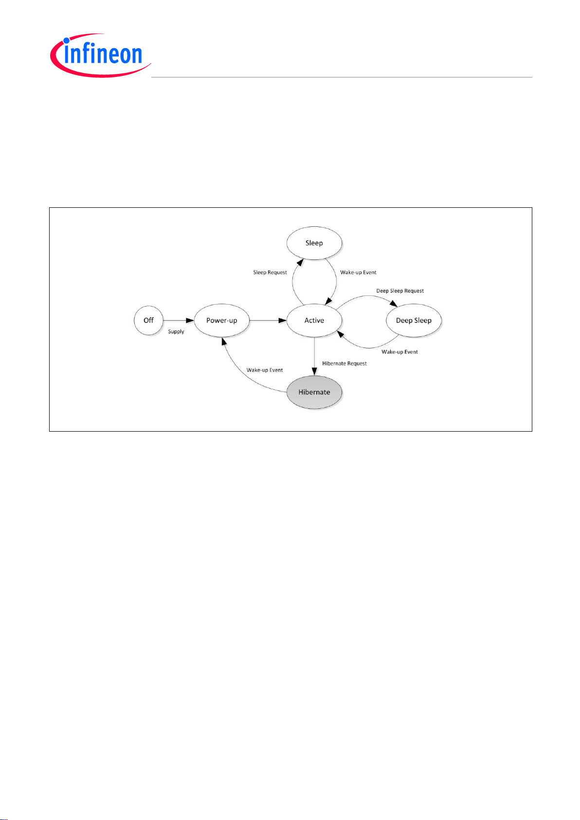
Hibernate Mode is one of the system power states of the XMC4000 device. The XMC4000 devices
implements Power Management control that aims at reduction of power consumption. The available
Power Modes (also referred to as Power States) of the system, depicted in Figure 1., offer different
features they may be utilized in an application specific manner, with the focus on different aspects,
like current consumption, transition time between states, system topology, etc.
Figure 1 System Power States
The XMC family implements the following Power Modes:
Active Mode - the normal operation state.
− Entered automatically after system reset release
Sleep Mode - clock of the CPU and selected peripherals is stopped.
− Entered via WFI or WFE instruction of the CPU (for details please refer to Cortex-M4
documentation)
− Wake-up on any valid interrupt/exception
Deep Sleep Mode – similar to Sleep Mode, with an ability to power down additional peripherals
− Entered via WFI or WFE instruction of the CPU (for details please refer to Cortex-M4
documentation)
− Wake-up on any valid interrupt/exception
Hibernate Mode – Power Supply to the chip or to the core (on some family XMC4000 family
members) is switched off and only Hibernate Domain remain powered on
The Hibernate Mode is the power mode of the lowest power consumption, offering Real Time Clock
keeping and preservation of a context specific data in a retention memory (for details on power
consumption and timing figures please refer to Data Sheet). Transitions into and from the power
states are controlled with user software and valid wake-up events respectively. The wake-up trigger
events may be generated by different sources, like external signals or RTC events, configured by the
user prior to entering a power saving state.
There are two implementations of the Hibernate Mode Control.
Externally Controlled Hibernate Mode (ECHM) with an IO actively controlling External Voltage
Regulator
Device Guide 6 V1.0, 2013-04
Page 7
Hibernate
XMC4000 Family
Hibernate Mode Basics
Internally Controlled Hibernate Mode (ICHM) with an internal signal actively controlling Embedded
Voltage Regulator (EVR)
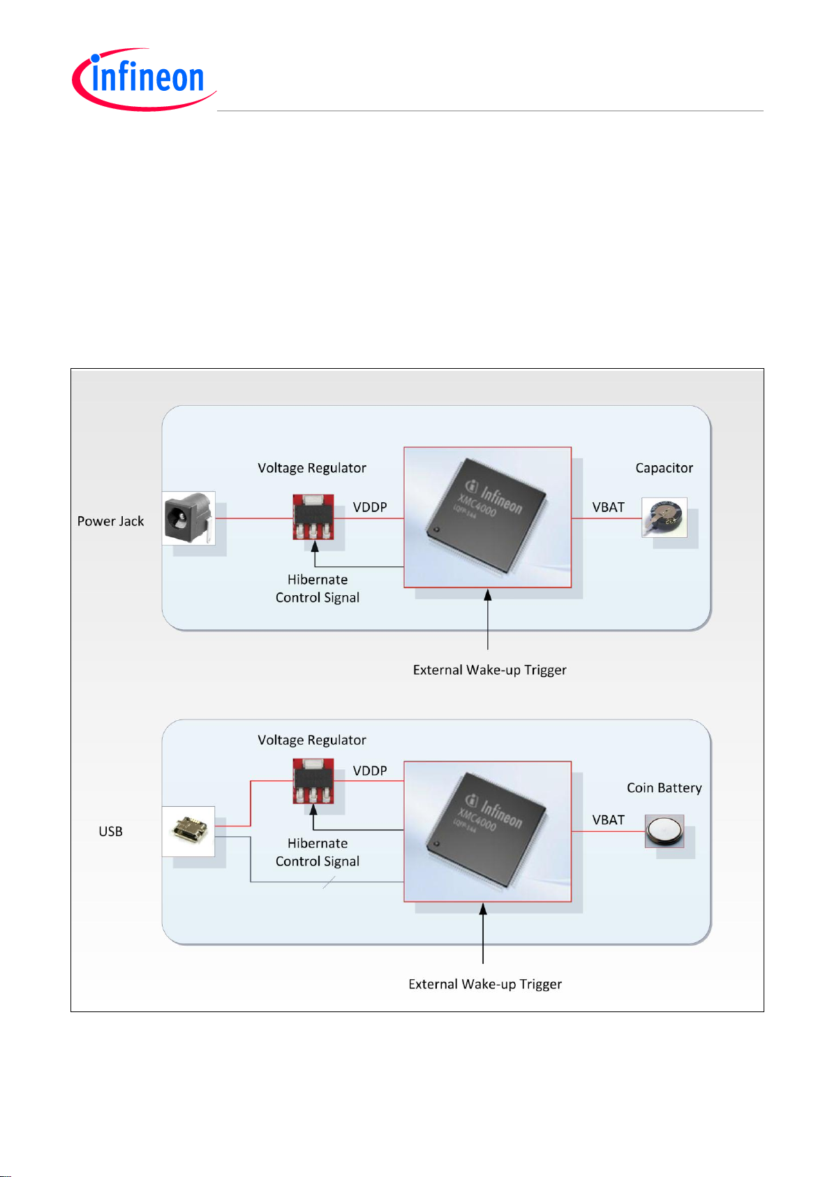
1.1 Externally Controlled Hibernate Use Cases
Generic application scenarios of Externally Controlled Hibernate Mode are illustrated in Figure 2.
These use case scenarios enable the XMC4000 to act as a system Power Control Master. All system
components supplied with VDDP are powered off and no current is drawn in the VDDP power
domain. Upon a wake-up trigger complete VDDP power domain of the system on PCB will be brought
into operation.
Figure 2 Examples of Externally Controlled Hibernate Mode use case
The external hibernate control is performed via the Hibernate Control Signal that will switch off the
Voltage Regulator providing VDDP voltage to all components of the board. VBAT will still be supplied
from an auxiliary source like e.g. a coin battery, or, a capacitor while in the Externally Controlled
Device Guide 7 V1.0, 2013-04
Page 8
Hibernate
XMC4000 Family
Hibernate Mode Basics
Hibernate Mode. A wake-up trigger will come from an external source and/or from the internal RTC
module.
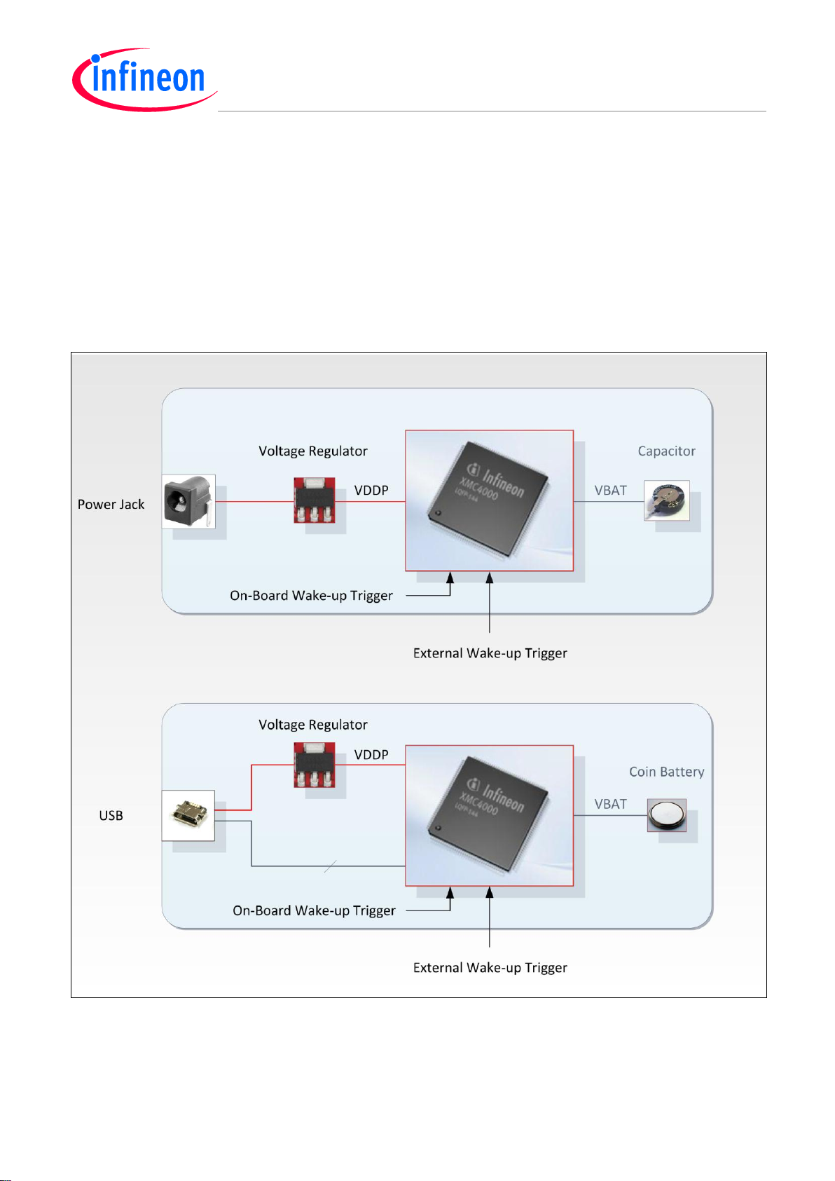
1.2 Internally Controlled Hibernate Use Cases
Generic application scenarios of Internally Controlled Hibernate Mode are illustrated in Figure 3.
These use case scenarios enable the XMC4000 to act as a system Power Control Slave. All system
components in the VDDP power remain powered on while Core Domain of the XMC4000 device is
powered off and I/Os are reset to input operation mode. Upon a wake-up trigger Core Domain of the
XMC4000 will be powered-up and brought into operation.
Figure 3 Examples of Internally Controlled Hibernate Mode use case
The internal hibernate control is performed via an internal circuit inside of the XMC4000 that will
switch off the Embedded Voltage Regulator providing VDDC voltage to the Core Domain of the chip.
While in Internally Controlled Hibernate Mode VBAT may still be supplied directly from the VDDP
source while main supply is available, and/or from an auxiliary source like e.g. a coin battery, or, a
Device Guide 8 V1.0, 2013-04
Page 9

Hibernate
XMC4000 Family
Hibernate Mode Basics
capacitor when the mains supply if off. A wake-up trigger will come from an external source and/or
from the internal RTC module and will enable Core Domain voltage generation (if VDDP is still
available).
Note: The Internally Controlled Hibernate Mode is not supported on XMC4500 device.
Device Guide 9 V1.0, 2013-04
Page 10

Hibernate
XMC4000 Family
Hibernate Mode Basics
Hibernate Mode
Implementations
Device Guide 10 V1.0, 2013-04
Page 11

Hibernate
Table 1 Hibernate Wake-up Triggers
Trigger Source
I/O Signals
Description
RTC event
n/a
RTC Alarm or RTC Periodic Event.
Watchdog of RTC external
crystal oscillator
n/a
The RTC external crystal oscillator (OSC_ULP) watchdog
is capable of generating a wakeup trigger if the RTC clock
generated with external crystal, or, a direct external clock
stops unexpectedly
Digital Input Signal
HIB_IO_0
HIB_IO_1
Exclusive selection of one of the digital inputs. Depending
of an application a rising and/or falling edge of the signal
may be selected as a wake-up trigger. For external
hibernate mode it is possible to combine Hibernate Control
and Wake-up function in the same digital IO. For availability
of the IOs please refer to the Data Sheet.
Analog Input Signal
HIB_IO_0
HIB_IO_1
Voltage threshold level crossing detection performed in the
Low Power Comparator (LPAC) module. Depending of an
application a rising and/or falling voltage event may be
selected as a wake-up trigger. The level crossing detection
can be performed continuously, periodically, or, may be
triggered with an external digital signal. Multiple analog
channels may be used for the wake-up trigger detection.
For availability of the LPAC module please refer to the Data
Sheet.
VBAT Supply Level Detection
VBAT
VBAT voltage detection can be performed with LPAC
module. Depending of an application a rising and/or falling
voltage event may be selected as a wake-up trigger. The
VBAT input level can be performed continuously,
periodically, or, triggered with an external digital signal. For
availability of the LPAC module please refer to the Data
Sheet.
XMC4000 Family
Hibernate Mode Implementations
2 Hibernate Mode Implementations
The two Hibernate Mode implementations, ECHM and ICHM, described in this section differ in the
way the core voltage generation control mechanism. However, the wake-up trigger detection
mechanism is the same for both Hibernate Mode implementations. The wakeup source can be digital
or analog, internal (RTC event) or external (input signal on an I/O). For more details please refer to
Table 1.
Various combinations of wake-up triggers are possible and a wide range of possible applications is
considered. The optimal selection of the Hibernate Mode and wake-up triggers application specific
requirements and availability of resources need to be taken in consideration.
Some system topologies may combine capabilities of both implementation of the Hibernate Mode and
can be applied interchangeably when required. However, only one of the Hibernate Modes can be
applied at the time.
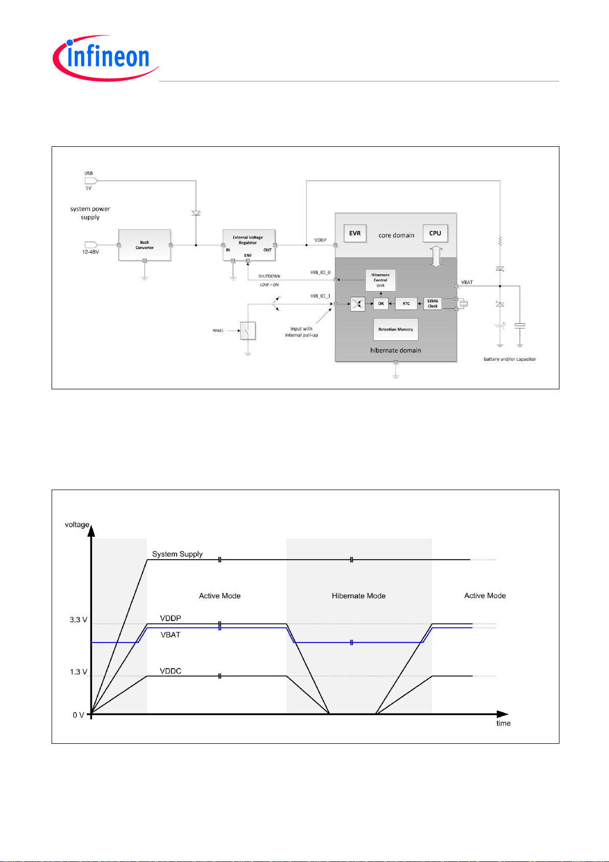
2.1 Externally Controlled Hibernate Mode Concept
The system configuration assumes that the XMC4000 device acts as the power management master
of the system on PCB and is capable to switch off/on the external Voltage Regulator. The Hibernate
Mode is entered by switching off the power supply VDDP of the device with the HIB_IO_0 pin. The
HIB_IO_0 pin remains in control of the External Voltage Regulator after entering Hibernate Mode
since entire Hibernate Domain remains supplied with the VBAT voltage from an auxiliary supply
Device Guide 11 V1.0, 2013-04
Page 12
Hibernate
XMC4000 Family
Hibernate Mode Implementations
voltage, e.g. a coin battery or a capacitor. A more detailed example scenario superset depicted in
Figure 1 shows the components of the complete system that enable use of the Hibernate Mode.
Figure 4 Externally Controlled Hibernate Mode Scenario
The Hibernate Control Unit (HCU) implements a circuit capable of controlling an External Voltage
Regulator via an I/O and detecting occurrence of an event matching user programmed wake-up
condition.
Entering Hibernate Mode is performed with a software request to a control register in the HCU module
which results in toggling an I/O connected to the External Voltage regulator.
Figure 5 Externally Controlled Hibernate Mode Power Sequencing
Device Guide 12 V1.0, 2013-04
Page 13

Hibernate
XMC4000 Family
Hibernate Mode Implementations
A wake-up trigger may be an external input signal (digital, or, on some XMC4000 family members,
also analog signal), or an RTC event. Upon a valid wake-up trigger the External Voltage Regulator
gets enabled to generate VDDP which results in complete power-up sequence of the chip.
The scenario shown in Figure 2. illustrates voltage generation sequence upon entering and leaving
Externally Controlled Hibernate. The main System Supply remains available on the PCB board. Upon
entering Hibernate Mode the VDDP output of the External Voltage Regulator gets switched off, and,
as consequence the Core Voltage of the XMC4000 (VDDC) is goes off. The VBAT voltage supplied
from an auxiliary source remains available, although it may or may not have a different level than the
valid VDDP supply level (for details please refer to Data Sheet).
Upon a wake-up from Hibernate Mode the VDDP generation in the External Voltage Regulator is
restarted, and, also Core Domain voltage generation starts automatically. The VBAT voltage is
supplied from VDDP via a (shottky) diode and may rise slightly if the VDDP has exceeded the voltage
level from an auxiliary source.
2.2 Internally Controlled Hibernate Mode Concept
The Internally Controlled Hibernate Mode is entered by switching off internally the Core Domain
VDDC voltage generation. After entering Hibernate Mode since entire Hibernate Domain remains
supplied with the VBAT voltage, derived from VDDP, or, from an auxiliary supply voltage, e.g. a coin
battery or a capacitor. A more detailed example scenario superset depicted in Figure 3. shows the
components of the complete system that enable use of the Hibernate Mode.
Figure 6 Internally Controlled Hibernate Mode Scenario
The Hibernate Control Unit (HCU) implements a circuit capable of controlling an Embedded Voltage
Regulator (EVR) via a power separation cell and detecting occurrence of an event matching user
programmed wake-up condition.
Entering Hibernate Mode is performed with a software request to a control register in the HCU module
which results in switching off the EVR.
A wake-up trigger may be an external input signal (analog or digital), a VBAT monitoring event, or, an
RTC event. Upon a valid wake-up trigger the EVR gets enabled to generate VDDC which results in
complete power-up sequence of the chip.
Device Guide 13 V1.0, 2013-04
Page 14

Hibernate
XMC4000 Family
Hibernate Mode Implementations
The scenario shown in Figure 4. illustrates voltage generation sequence upon entering and leaving
Internally Controlled Hibernate. The main System Supply and VDDP remain available on the
application board. Upon entering Hibernate Mode the VDDC output of the EVR gets switched off, and,
as consequence the Core Domain is powered off. The VBAT voltage supplied from an VDDP remains
available.
Figure 7 Internally Controlled Hibernate Mode Power Sequencing
Upon a wake-up from Hibernate Mode the VDDC generation in the EVR is restarted automatically.
It is important to keep in mind that pads in the VDDP power domain remain supplied while in the
Internally Controlled Hibernate Mode but are automatically reconfigured into input mode. The PORST
reset gets activated (active low) and internal pull-up on the PORST reset pin gets automatically deactivated in order to minimize current consumption. After a wake-up trigger detection the pull-up on
PORST gets activated, the PORST reset gets released as soon as the core voltage VDDC generation
is restored.
Device Guide 14 V1.0, 2013-04
Page 15

Hibernate
XMC4000 Family
Hibernate Mode Implementations
Control of Exernal Voltage
Regulator
Device Guide 15 V1.0, 2013-04
Page 16

Hibernate
Table 2 External Voltage Regulator Control Scheme Guidance
External Voltage Regulator
Control Scheme
Enable Signal
Level/Control
IO
Features/Hitns
Active high enable via pull-up
high/HIB_IO_1
One pull-up resistor on PCB required
Very low current consumption from V
BAT
source
Suitable for use with a golcap as V
BAT
source
Active high enable driven from
a voltage divider
high/HIB_IO_1
Two pull-up resistors on PCB required
Very low current consumption from V
BAT
source
Suitable for use with a golcap as V
BAT
source
Wake-up triggered while
Active low enable driven with
push-pull I/O
low/HIB_IO_0
Simple, no external components on PCB required
Higher Voltage on V
BAT
source may be required
Extra current drained from V
BAT
source
Not suitable for use with a goldcap as V
BAT
source
Active low enable and with pullup to high
low/HIB_IO_0
One pull-up resistor on PCB required
Very low current consumption from V
BAT
source
Possible control and wake-up trigger on one pin
Suitable for use with a golcap as V
BAT
source
Active low enable driven from a
voltage divider
low/HIB_IO_0
Two pull-up resistors on PCB required
Very low current consumption from V
BAT
source
Possible control and wake-up trigger on one pin
Suitable for use with a golcap as V
BAT
source
External wake-up detection supply failure tollerant
Active low enable driven from a
voltage divider and V
BAT
low/HIB_IO_0
Two pull-up resistors and 2 diodes on PCB required
Very low current consumption from V
BAT
source
Possible control and wake-up trigger on one pin
Suitable for use with a golcap as V
BAT
source
External wake-up detection supply failure tollerant
XMC4000 Family
Control of External Voltage Regulator
3 Control of External Voltage Regulator
Generally, External Voltage Regulators with on/off control input implement various control schemes
and may impose special requirements on the voltage levels and driving strength of the control signal.
It needs to be noted that the hibernate control signals HIB_IO_0 and HIB_IO_1 implement different
default driver configurations. This fact needs to be taken in account for PCB design and is determined
by the selection of the External Voltage Regulator control scheme.
The HIB_IO_0 is configured as open drain driver and is driving level low after rest of the Hibernate
Domain.
The HIB_IO_1 is configured to high impedance mode after reset of the Hibernate Domain and needs
to be configured accordingly before used for hibernate control purpose.
Typically External Voltage Regulators are enabled with logic high level and disabled/shut down with
logic low control signal. This kind of Voltage regulators may be controlled with a hibernate control I/O
of XMC4000 device with an external pull-up resistor to a voltage that is equal or above the minimum
required logic high level of the External Voltage Regulator.
The Table 1 provides a quick guidance for some implementations of the External Voltage Regulator
control.
Device Guide 16 V1.0, 2013-04
Page 17

Hibernate
XMC4000 Family
Control of External Voltage Regulator
3.1 Active high enable via pull-up
A simple implementation of the scheme is illustrated in the Figure 1. The voltage V
the EN pin of the External Voltage Regulator via the pull-up resistor R1 in order to drive level high.
The hibernate control signal, configured as open drain driver, is in high impedance state when high is
driven from the Hibernate Control Unit. When the hibernate control signal is driving level low, the pullup driving V
gets overcome with the strong driver inside the XMC4000 device. The V
CTLR
assumed to fulfill the requirement:
V
EN min
≤ V
CTRL
≤ V
EN max
,
where the V
EN min
and V
EN max
are the minimum and maximum control input voltage levels for the
External Voltage Regulator, respectively.
In typical case the Supply Voltage is suitable to drive the EN control input high (for details please
refer to specification of the External Voltage Regulator). The V
may also be supplied from VBAT,
CTLR
but it may lead e.g. to a coin shorter battery life or quicker discharge of a capacitor supplying
Hibernate Domain while in Hibernate Mode, therefore in most application scenarios should be
avoided.
connected to
CTRL
CTLR
is
Figure 8 External Voltage Regulator with active high enable via pull-up
For applications where the External Voltage Regulator is active when the control signal is high it is
required to use the HIB_IO_1 I/O as the hibernate control signal in order to ensure reliable start of the
device after reset of the hibernate domain, as illustrated in Figure 2. After Hibernate Domain reset the
HIB_IO_1 signal is in high impedance state and the External Voltage Regulator will control input is
driven high via the R1 pull-up resistor which enables VDDP voltage generation and start of the
system.
Device Guide 17 V1.0, 2013-04
Page 18

Hibernate
XMC4000 Family
Control of External Voltage Regulator
Figure 9 External Voltage Regulator with active high enable via pull-up after reset
3.2 Active high enable driven from a voltage divider
I case a high level of the EN control signal of the External Voltage Regulator cannot be driven using a
simple pull-up it may be necessary to generate a suitable voltage source. This can be realized with a
resistive voltage divider apply a voltage as illustrated in Figure 3.
Figure 10 External Voltage Regulator with active high enable from a voltage divider
This solution allows applying V
voltage:
CTRL
V
EN max
≤ V
CTRL
,
Device Guide 18 V1.0, 2013-04
Page 19

Hibernate
XMC4000 Family
Control of External Voltage Regulator
where the V
maximum control input voltage level for the External Voltage Regulator.
EN min
The values of the R1 and R2 resistors of the voltage divider shall be possibly high in order to enable
to the HI_IO_1 signal to override with signal level low when driven with the open drain driver.
A potential advantage of this topology is that the V
used to generate the enable signal for the
CTRL
External Voltage Regulator may be independent from its Supply Voltage. This may be useful if the
Supply Voltage of the External Voltage Regulator gets lowered while in Hibernate Mode and a valid
wake-up trigger gets detected. The enable signal driven to the External Voltage Regulator will also
reach a valid level, i.e. above the V
EN min
.
3.3 Active low enable driven with push-pull I/O
In case of a low enabled External Voltage Regulator the control scheme is largely simplified and may
be realized with direct connection from push-pull I/O driver of the XMC4000 device, without additional
components on the PCB. This scheme require that the HIB_IO_0 pin is used as the control signal
because it's by default configured as default open drain driver, allowing startup of the system after
Hibernate Domain has been reset, which is the case after initial power up. After startup of the system
the HIB_IO_0 needs to be reconfigured to pus-pull driving mode.
This configuration requires that the following condition is fulfilled:
V
where the V
External Voltage Regulator, respectively, V
While in Hibernate Mode the current required to drive the #EN control input of the External Voltage
Regulator is drained from VBAT source and it needs to be taken in account that it may result e.g. in a
shorter life of a coin battery. Use of a capacitor may be limited due to potentially narrow range of the
EN signal voltage range. It may be difficult to maintain the required voltage level in the capacitor over
a longer period of Hibernate Mode.
EN min
≤ V
BAT
≤ V
EN min
EN max
and V
,
EN max
are the minimum and maximum control input voltage levels for the
is the supply voltage of the Hibernate Domain.
BAT
Figure 11 External Voltage Regulator with active low direct enable
Device Guide 19 V1.0, 2013-04
Page 20

Hibernate
XMC4000 Family
Control of External Voltage Regulator
3.4 Active low enable and with pull-up to high
Another flavor of the configuration with a low enable capable External Voltage Regulator assumes a
pull-up to a V
must fulfilled for the V
V
EN min
≤ V
CTRL
where the V
External Voltage Regulator, respectively.
voltage in order to drive #EN high, as depicted inFigure 5. The following condition
CTLR
voltage:
CTLR
≤ V
EN min
,
EN max
and V
EN max
are the minimum and maximum control input voltage levels for the
Figure 12 External Voltage Regulator with active low enable via a pull-up
This configuration offers attractive power consumption feature while in Hibernate Mode if the V
CTRL
is
supplied e.g. from the Supply Voltage. The current drained on the #EN input of the External Voltage
Regulator while in Hibernate Mode does not discharge the V
source e.g. a coin battery. Moreover,
BAT
the control function of the HIB_IO_0 pin can also be combined with a wake-up trigger function on
negative edge. The control signal high can be overridden by a signal low from a stronger (open drain)
driver, creating a negative signal edge.
3.5 Active low enable driven from a voltage divider
I case a high level of the #EN control signal of the External Voltage Regulator cannot be driven using
a simple pull-up it may be necessary to generate a suitable voltage source. This can be realized with
a resistive voltage divider apply a voltage as illustrated in Figure 6.
Device Guide 20 V1.0, 2013-04
Page 21

Hibernate
XMC4000 Family
Control of External Voltage Regulator
Figure 13 External Voltage Regulator with active low enable from a voltage divider
This solution allows to apply V
voltage:
CTRL
V
EN max
≤ V
CTRL
,
where the V
maximum control input voltage level for the External Voltage Regulator.
EN min
The values of the R1 and R2 resistors of the voltage divider shall be possibly high in order to enable
to the HI_IO_0 signal to override with signal level low when driven with the open drain driver.
A potential advantage of this topology is that the V
used to generate the enable signal for the
CTRL
External Voltage Regulator may be independent from its Supply Voltage. This may be useful if the
Supply Voltage of the External Voltage Regulator gets lowered while in Hibernate Mode and the
HIB_IO_0 I/O is also serving input purpose for an external wake-up trigger. The wake-up trigger
(negative edge) will get detected reliably since it will reach a valid level. This implies also that enable
signal driven to the External Voltage Regulator will also reach a valid level, i.e. above the V
EN min
. This
may not result in immediate wake-up and proper power up of the XMC4000 device is the Supply
Voltage remain below the minimum level to generate a valid VDDP (for details please refer to Data
Sheet) but the wake-up will eventually occur when the supply condition has improved.
3.6 Active low enable driven from a voltage divider and V
BAT
A more complex topology shown in Figure 7 offers a superset combination of the features described
in previous paragraphs. The External Voltage Regulator control is combined with a wake-up trigger
(falling edge) on the HIB_IO0 I/O of the XMC4000 device. The #EN signal gets generated with the
pull-up resistor to the Supply Voltage of the External Voltage Regulator. The wake-up trigger
detection will function reliably also when the Supply Voltage drops down below a minimum level of the
V
voltage and will effectively bring up the system into operation as soon as the proper Supply
BAT
Voltage is restored.
Device Guide 21 V1.0, 2013-04
Page 22

Hibernate
XMC4000 Family
Control of External Voltage Regulator
Figure 14 External Voltage Regulator with active low enable from a voltage divider
The following condition must fulfilled for the V
V
EN min
≤ V
CTRL
≤ V
EN max
,
voltage:
CTLR
where the V
EN min
and V
EN max
are the minimum and maximum control input voltage levels for the
External Voltage Regulator, respectively.
Device Guide 22 V1.0, 2013-04
Page 23

Hibernate
XMC4000 Family
Control of External Voltage Regulator
Getting Started
Device Guide 23 V1.0, 2013-04
Page 24

Hibernate
XMC4000 Family
Getting Started
4 Getting Started
The Flowchart in the Figure 1 shows the generic sequence of actions required to enter and wake-up
from a Hibernate Mode. It is assumed that the system on PCB implements a superset of resources
required to make use of any of the Hibernate Modes (example topology that may be applicable here
can be found in the Figure 2)
Figure 15 Hibernate Sequence
Device Guide 24 V1.0, 2013-04
Page 25

Hibernate
XMC4000 Family
Getting Started
The Hibernate Mode control register located in the Hibernate Control Unit can be accessed via mirror
registers. Before writing to any of the registers it is required to check if the corresponding status bits in
the SCU_MIRRSTS register indicate that a new access can be accepted.
4.1 Initialize Hibernate Domain
The Hibernate Domain needs to be enabled and/or released from reset state before it can be used.
Typically, this needs to be done after power-up of the Hibernate Domain. This step may be omitted if
the Hibernate Domain is already initialized.
Enable Hibernate Domain
Set bit SCU_PWRSET.HIB
Release reset of Hibernate Domain (if asserted)
Clear bit SCU_RSTCLR.HIBRS
Enable and configure Ultra Low Power Oscillator if a high precision clock required
Configure SCU_OSCULCRTL.MODE
Note: startup of the RTC external crystal oscillator may take some, please refer to Data Sheet for
details
Select the clock source and start RTC if Real Time Clock required.
Select clock in SCU_HDCR.RCS
Set current time in RTC
Write to registers RTC.TIM0 and RTC.TIM1
Enable RTC module with RTC_CTR register
Set bit RTC_CTR.ENB
Example pseudo-code:
//Enable Hibernate Domain
SCU_POWER->PWRSET = 0x1 << SCU_POWER_PWRSET_HIB_Pos;
//Release Hibernate Domain from reset state
SCU_RESET->RSTCLR = 0x1 << SCU_RESET_RSTCLR_HIBRS_Pos;
//Enable RTC external clock oscillator
Device Guide 25 V1.0, 2013-04
Page 26

Hibernate
XMC4000 Family
Getting Started
SCU_HIBERNATE->OSCULCTRL &= ~SCU_HIBERNATE_OSCULCTRL_MODE_Msk;
//Select external crystal oscillator as RTC clock source
//wait until HDCR register ready for a write
do {
}
while ( SCU_GENERAL->MIRRSTS & SCU_GENERAL_MIRRSTS_HDCR_Msk));
//write 1 to SCU_HDCR.RCS
SCU_HIBERNATE->HDCR &= (~SCU_HIBERNATE_HDCR_RCS_Msk) | (0x1 << SCU_HIBERNATE_HDCR_RCS_Pos);
//wait around 10 ms
wait (10);
//Program RTC time
//wait until RTC.TIM0 and RTC.TIM1 ready for a write
do {
}
while ( SCU_GENERAL->MIRRSTS & \
(SCU_GENERAL_MIRRSTS_RTC_TIM0_Msk | SCU_GENERAL_MIRRSTS_RTC_TIM0_Msk1));
//write to TIM0 and TIM1
RTC->TIM0 = time_day_hours_minutes_seconds;
RTC->TIM1 = time_years_months_days_day_of_week;
//start RTC counter
RTC->CTR |= 0x1 << RTC_CTR_ENB_Pos;
4.2 Store Context Data in Retention Memory
The application context specific data can be optionally stored in the Retention Memory in Hibernate
Domain for a later use, i.e. after a wake-up. The Retention Memory can be accessed via dedicated
Mirror Registers. The Retention Memory is comprised of 16 x 32-bit registers.
Write data to SCU_RMDATA register and Issue a write command with SCU_RMACR.
Examine the mirror status register bit SCU_MIRRSTS.RMX before each write to SCU_RMACR and
make sure that no new write is performed before it has been cleared.
This step may also be specific to an Operating System.
Example pseudo-code:
//Write data to address 0x4 of the Retention Memory
//store a write data for a write to retention memory in SCU_RMDATA register
SCU_GENERAL->RMDATA = data;
//wait until RMACR register ready for a write command
do {
}
while ( SCU_GENERAL->MIRRSTS & SCU_GENERAL_MIRRSTS_RMX_Msk);
//write data to address 0x4
SCU_GENERAL->RMACR = (0x4 << SCU_GENERAL_RMACR_ADDR_Pos) | (0x1 << SCU_GENERAL_RMACR_RDWR_Pos);
Device Guide 26 V1.0, 2013-04
Page 27

Hibernate
XMC4000 Family
Getting Started
4.3 Select Wake-up Triggers
Various kinds of trigger may be selected to wake-up the system from a hibernate mode, see Table 1.
For availability of the wake-up sources please refer to Data Sheet of the device.
RTC event
Select RTC wake up event with SCU_HDCR.RTCE
Configure RTC periodic event (if required) with RTC_CTR register
Configure RTC alarm with RTC_ATIM0 and RTC_ATIM1 registers and enable wit RTC_CTR.TAE
Clear RTC event status bit with SCU_HDCLR.RTCEV
Watchdog of RTC external crystal oscillator
Select the watchdog event as a wake-up trigger with SCU_HDCR.ULPWDGEN
Clear the watchdog trigger status with SCU_HDCLR.ULPWDG
Trigger on a digital I/O
Select trigger active edge with SCU_HDCR.WKPEP and with SCU_HDCR.WKPEN
Select a digital I/O as the digital trigger input with SCU_HDCR.WKUPSEL
Configure digital I/O input properties with SCU_HDCR.HIBIO0SEL or SCU_HDCR.HIBIO1SEL
Clear the Digital Input Signal trigger status with SCU_HDCLR.EPEV
Clear the Digital Input Signal trigger status with SCU_HDCLR.ENEV
Trigger on analog I/Os
Initialize/configure the LPAC module, select analog channels, set thresholds
Select wakeup on HIB_IO_0 negative threshold crossing with SCU_HDCR.AHIBIO0LO
Select wakeup on HIB_IO_0 positive threshold crossing with SCU_HDCR.AHIBIO0HI
Select wakeup on HIB_IO_1 negative threshold crossing with SCU_HDCR.AHIBIO1LO
Select wakeup on HIB_IO_1 positive threshold crossing with SCU_HDCR.AHIBIO1HI
Configure analog I/O input properties with SCU_HDCR.HIBIO0SEL or SCU_HDCR.HIBIO1SEL
Clear the analog HIB_IO_0 Input Signal trigger status with SCU_HDCLR.HIBIO0LO
Clear the analog HIB_IO_0 Input Signal trigger status with SCU_HDCLR.HIBIO0HI
Clear the analog HIB_IO_1 Input Signal trigger status with SCU_HDCLR.HIBIO1LO
Clear the analog HIB_IO_1 Input Signal trigger status with SCU_HDCLR.HIBIO1HI
VBAT Supply Level Detection
Initialize/configure the LPAC module, select analog channels, set thresholds
Select wakeup on a VBAT negative threshold crossing with SCU_HDCR.VBATLO
Select wakeup on a VBAT positive threshold crossing with SCU_HDCR.VBATHI
Device Guide 27 V1.0, 2013-04
Page 28

Hibernate
XMC4000 Family
Getting Started
Clear the analog Input Signal trigger status with SCU_HDCLR.VBATLO
Clear the analog Input Signal trigger status with SCU_HDCLR.VBATHI
Example pseudo-code:
//wait until SCU_HDCR register ready for a write
do {
} while ( SCU_GENERAL->MIRRSTS & SCU_GENERAL_MIRRSTS_HDCR_Msk);
//write 1 to HDCR.RTCE in order to enable wake-up on RTC event
SCU_HIBERNATE->HDCR &= (~SCU_HIBERNATE_HDCR_RTCE_Msk) | (0x1 << SCU_HIBERNATE_HDCR_RTCE_Pos);
//wait until SCU_HDCR register ready for a write
do {
} while ( SCU_GENERAL->MIRRSTS & SCU_GENERAL_MIRRSTS_HDCR_Msk);
//write 1 to HDCR.WKPEN in order to enable wake-up on negative edge of a digital
//input
SCU_HIBERNATE->HDCR &= (~SCU_HIBERNATE_HDCR_WKPEN_Msk) | (0x1 << SCU_HIBERNATE_HDCR_WKPEN_Pos);
Note: All the consecutive writes to the SCU_HDCR register above can be combined in a single write of
a multiple bits to the SCU_HDCR register
4.4 Configure Hibernate Control I/O
Digital outputs polarity
Configure digital I/O output polarity with SCU_HDCR.HIBIO0POL or SCU_HDCR.HIBIO1POL
Select hibernate control output and driver properties
Configure digital I/O output properties with SCU_HDCR.HIBIO0SEL or SCU_HDCR.HIBIO1SEL
Example pseudo-code:
//wait until SCU_HDCR register ready for a write
do {
} while ( SCU_GENERAL->MIRRSTS & SCU_GENERAL_MIRRSTS_HDCR_Msk);
//write 1 to HDCR.HIBPOL0 in order to ensure that External Voltage Regulator
//control signal is low when Externally Controlled Hibernate is activated via
//HIB_IO_0 pin
Device Guide 28 V1.0, 2013-04
Page 29

Hibernate
XMC4000 Family
Getting Started
SCU_HIBERNATE->HDCR &= (~SCU_HIBERNATE_HDCR_HIBPOL0_Msk) | (0x1 << SCU_HIBERNATE_HDCR_ HIBPOL0 _Pos);
//wait until SCU_HDCR register ready for a write
do {
} while ( SCU_GENERAL->MIRRSTS & SCU_GENERAL_MIRRSTS_ HDCR_Msk);
//write 0XC to HDCR.HIBIO0SEL in order to configure the HIB_IO_0 I/O as open drain
//driver
SCU_HIBERNATE->HDCR &= (~SCU_HIBERNATE_HDCR_HIBIO0SEL_Msk) | (0xC << SCU_HIBERNATE_HDCR_
HIBIO0SEL_Pos);
Note: All the consecutive writes to the SCU_HDCR register above can be combined in a single write of
a multiple bits to the SCU_HDCR register
4.5 Request External Hibernate Mode
Request Hibernate Mode
Set SCU_HDCR.HIB
Wait for hibernate to take effect
Prevent casual code execution, e.g. stay in an endless loop or idle process (in case of an Operating
System)
Example pseudo-code:
//wait until SCU_HDCR register ready for a write
do {
} while ( SCU_GENERAL->MIRRSTS & SCU_GENERAL_MIRRSTS_HDCR_Msk));
//write 1 to HDCR.HIB
SCU_HIBERNATE->HDCR &= (~SCU_HIBERNATE_HDCR_HIB_Msk) | (0x1 << SCU_HIBERNATE_HDCR_HIB_Pos);
//stay in endless loop
while (1){};
Note: All the consecutive writes to the SCU_HDCR register can be combined in a single write of a
multiple bits to the SCU_HDCR register
4.6 Request Internal Hibernate Mode
Request Hibernate Mode
Set SCU_HINSET.HIBNINT
Wait for hibernate to take effect
Device Guide 29 V1.0, 2013-04
Page 30

Hibernate
XMC4000 Family
Getting Started
Prevent casual code execution, e.g. stay in an endless loop or idle process (in case of an Operating
System)
Example pseudo-code:
//wait until SCU_HITSET register ready for a write
do {
} while ( SCU_GENERAL->MIRRSTS & SCU_GENERAL_MIRRSTS_HINTSET_Msk);
//write 1 to SCU_HINSET.HIBNINT
SCU_HIBERNATE->HINTSET = (0x1 << SCU_HIBERNATE_HINTSET_HIBINT_Pos);
//stay in endless loop
while (1){};
4.7 Hibernate Mode Entered
Hibernate Mode has been entered; no software is running on CPU, entire core domain Core Domain
is in power-off state. Hibernate domain is waiting for a wake-up trigger.
Externally Controlled Hibernate Mode
VDDP supply removed,
Pads (except for Hibernate domain pads) powered off
Internally Controlled Hibernate Mode
VDDP supply present,
Pads (except for the Hibernate domain pads) in input mode,
PORST reset asserted
VDDC generation disabled
4.8 Wake-up Trigger Detected
A valid wake-up trigger event detected in the Hibernate Control Unit (HCU), wake-up process starting.
No user code involved, handled in hardware.
Externally Controlled Hibernate Mode
Hibernate Control I/O (HIB_IO_0 or HIB_IO_1)) toggling in order to enable External Voltage Regulator
to start generation of VDDP
Internally Controlled Hibernate Mode
Control signal to EVR generated in order to start VDDC generation
Device Guide 30 V1.0, 2013-04
Page 31

Hibernate
XMC4000 Family
Getting Started
4.9 Power-up and Boot-up
No user code involved, handled in hardware and Firmware
Power of the chip restored
Resets released
Execution of the Firmware (Boot-up code)
4.10 Processing of Wake-up Cause Info
Detection of a wakeup from Hibernate mode
Examine the SCU_RSTSTAT. HIBWK
Detection of the last reset cause
Examine (optionally) the SCU_RSTSTAT. RSTSTAT in order to determine if the last reset was
caused by power-off
Detection of the source wake-up trigger
Examine the wake-up trigger source in SCU_HDSTAT register bit fields.
Example pseudo-code:
//Read and interpret wake-up info from SCU_RSTSTAT. HIBWK
If (SCU_RESET->RSTSTAT.HIBWK)
{
wakeup_occured_flag = true;
}
else
{
wakeup_occured_flag = false;
}
//Read and interpret wake-up info from SCU_RSTSTAT. RSTSTAT
reset_cause = SCU_RESET->RSTSTAT. RSTSTAT;
if (reset_cause & PORST & SWD & PV )
{
power_up_occured = true; //a normal power up occurred
…
}
if (reset_cause & WDT )
{
watchdog_reset_occured = true; //a reset caused by watchdog
…
}
Device Guide 31 V1.0, 2013-04
Page 32

Hibernate
XMC4000 Family
Getting Started
if (reset_cause & PARITY )
{
parity_reset_occured = true; //reset caused by a parity error
…
}
…
4.11 Clear Reset Status
Reset status register needs to be cleared before a new reset cause can be effectively captured
Clear wakeup-up status
Clear SCU_RSTSTAT. HIBWK with SCU_RSTCLR.HIBWK
Clear reset status register
Clear SCU_RSTSTAT. RSTSTAT with SCU_RSTCLR.RSTSTAT
4.12 Restore Context Data from Retention Memory
Restore context specific data from the retention memory if a wake-up from Hibernate Mode has been
positively detected in the previous steps. The use of the data is application specific.
Issue a read command with SCU_RMACR.
Read data from SCU_RMDATA register
Example pseudo-code:
//Read data from address 0x4 of the Retention Memory
//wait until RMACR register ready for a read command
do {
} while ( SCU_GENERAL->MIRRSTS & SCU_GENERAL_MIRRSTS_RMX_Msk));
//write address 0x4
SCU_GENERAL->RMACR = (0x4 << SCU_GENERAL_RMACR_ADDR_Pos);
//wait until data available in the RMDATA register
do {
} while ( SCU_GENERAL->MIRRSTS & SCU_GENERAL_MIRRSTS_RMX_Msk));
//read data for a write to retention memory in SCU_RMDATA register
Data = SCU_GENERAL –> RMDATA;
4.13 Execute Application Code
The application code starts.
The application code execution flow may depend on the wake-up source and context.
This step may also be specific to an Operating System.
Device Guide 32 V1.0, 2013-04
Page 33

Hibernate
XMC4000 Family
Getting Started
Device Guide 33 V1.0, 2013-04
Page 34

Hibernate
XMC4000 Family
Getting Started
Application Hints
Device Guide 34 V1.0, 2013-04
Page 35

Hibernate
Table 3 Selection of the Hibernate Mode implementation
Features/hints
ECHM
ICHM
Power Consumption in
Hibernate Mode
Ultra Low
Very Low
External Voltage Regulator
Required External Voltage Regulator
capable of on/off control
Simple External Voltage Regulator
I/Os required
Minimum one I/O of Hibernate
Domain
Possible without dedicated I/Os
Complexity of the circuit
pull-up resistors required
possible without pull-up resistors
Use cases
XMC4000 acting as the system
power control master on the
PCB
Higher pin count packages
Battery operated devices
XMC4000 acting as the system
power control slave on the PCB
Low pin count packages
Power Supply Permanently available
Table 4 Hibernate Domain Clock Source Selection
Trigger Source
Pins
Features/Hints
Internally generated clock
source
n/a
Low Bill of Material
Low power consumption
Most reliable RTC clock under all conditions
Moderate Real Time Clock accuracy
Externally generated clock
source
RTC_XTAL0 &
RTC_XTAL1
Moderate Bill of Material
Very low power consumption
Very High Real Time Clock accuracy
Constrained PCB design
Direct clock applied to the RTC
clock pin
RTC_XTAL0
Higher Bill of Material
Easy PCB design
External oscillator supply required
XMC4000 Family
Application Hints
5 Application Hints
5.1 Which Hibernate Mode to Choose
The optimal selection of the Hibernate Mode implementation is application specific and shall take in
account requirements on current consumption, availability of on-chip and off-chip resources, cost etc.
Some of the key points important from an application use case point of view shown in Table 1.
5.2 Hibernate Domain Clock
The Hibernate domain clock is clocked with 32.768 MHz clock. The source of the clock may be
selected:
Internally generated clock source - Slow Internal Clock Source
Externally generated clock source - OSC_SI oscillator with an external crystal
Direct clock applied to the RTC clock pin
The choice of the clock shall be determined by the application specific requirements:
Device Guide 35 V1.0, 2013-04
Page 36

Hibernate
XMC4000 Family
Application Hints
5.3 Digital I/O Voltage Levels
In a typical Hibernate Mode application scenario the VBAT voltage level may be slightly lower than
VDDP while in active mode due to presence of additional components e.g. a shottky diode between
the VDDP and VBAT pin. Also, the VBAT level supplied to the chip may be even lower, and below
any other supply sources on the PCB board which may potentially result in violation of the
input/output voltage levels at the Hibernate Domain IOs (For details on voltage limits on I/Os please
refer to Data Sheet). Therefore it is highly recommended to:
Apply Open-Drain configuration with external pull-up to valid logic level high of the target signal for
the output I/Os. The impedance of the pull-up shall be determined by the internal impedance of the
input of the target circuit and the limits of the output I/O driver. The pull-up impedance needs to be
dimensioned accordingly in order to avoid violation of the logic low level of the Hibernate Domain
I/O limits. For details on the I/O limits please refer to Data Sheet.
Drive the input I/Os with Open-Drain drivers and enable internal pull-up of the XMC4000 device to
the VBAT voltage.
5.4 Analog I/O Voltage Levels
The voltage ranges for analog I/O wake-up trigger signals have a fixed maximum limit (For details
please refer to Data Sheet), which is always below a valid VBAT voltage level. It is required to ensure
that the output voltage level of a circuit connected to the analog wake-up trigger I/O according meets
the specified limits. This can be easily done with a resistive voltage divider implemented on PCB, in
front of the analog I/O of the XMC4000 device as depicted in Figure 1. The resistors R1 and R2 need
to be dimensioned accordingly.
Figure 16 Analog signal input voltage divider
It is highly recommended to apply (possibly) high resistance R1 and R2 in to minimize the overall
current in order to take maximum advantage of the power saving while in the Hibernate Mode.
5.5 Retention Memory
The internal Retention Memory in Hibernate Domain serves general purpose storage for context
specific information to be used after a wake-up. This may include information e.g. on:
Device Guide 36 V1.0, 2013-04
Page 37

Hibernate
Table 5 Recovery Scenarios
Hibernate Mode
Action
Comments
Externally & Internally
Controlled Hibernate Modes
Hibernate Domain
Reset
Remove the V
BAT
supply – not practicable e.g. if a coin
battery soldered on the PCB.
Lower the V
BAT
level below reset threshold level – avoid a
shortcut to ground, may damage the battery
Externally Controlled Hibernate
Mode
Force generation
of VDDP
Presence of VDDP supply will unconditionally force startup
of the XMC4000 device, the Hibernate Domain will not get
reset.
This may be realized e.g. with a button allowing overwriting
control signal of the External Voltage Regulator and forcing
generation of VDDP, while V
BAT
remains supplied.
Internally Controlled Hibernate
Mode
Force removal of
VDDP
Removal of VDDP supply will unconditionally remove
Hibernate Mode. After reapplying VDDP supply the
XMC4000 will start-up, the Hibernate Domain will not get
reset.
This may be realized e.g. by physically removing the
module from the system, or, with a button allowing to
overwriting control signal of the External Voltage Regulator
and forcing removal of VDDP, while V
BAT
remains supplied.
XMC4000 Family
Application Hints
reason for entering hibernate
expected wake-up source relevant to the recent hibernate state
action to be taken after a wakeup
The data stored in the Retention Memory has no direct effect on the hardware and it is entirely under
the application software control.
5.6 Emergency Recovery from Hibernate Mode
It may happen that the system gets into a lock-up situation if a Hibernate Mode has been entered
without a wake-up trigger selected. The XMC4000 device may permanently stay in the Hibernate
State unless a corrective recovery action has been taken in order to bring it into operation. A few
recovery hints are presented in the Table 3.
Device Guide 37 V1.0, 2013-04
Page 38

Published by Infineon Technologies AG
w w w . i n f i n e o n . c o m
 Loading...