

Page 1

Application Note Please read the Important Notice and Warnings at the end of this document Revision 1.0
www.infineon.com 2016-11-01
AN_GS_201611_PL21_003
Getting Started with the XDPL8220 Reference
Board Using .dp Vision Software
XDPTMdigital power
About this document
Scope and purpose
The purpose of this document is to give a quick guide how to operate the XDPL8220 reference board of all
power classes for LED lighting applications and use the .dp Vision software to programm the operating
parameters of the digital controller XDPL8220.
Intended audience
This document is intended for anyone who wants to evaluate the XDPL8220 reference design for LED lighting.
Table of Contents
About this document....................................................................................................................... 1
Table of Contents ........................................................................................................................... 1
1 Hardware...................................................................................................................... 2
1.1 Required Hardware tools........................................................................................................................2
1.2 Hardware Connection.............................................................................................................................3
2 Software....................................................................................................................... 6
2.1 Required Software Tools.........................................................................................................................6
2.2 Software Installation............................................................................................................................... 7
3 Getting Started.............................................................................................................. 8
Revision History ............................................................................................................................13
Page 2
Application Note 2 Revision 1.0
2016-11-01
Getting Started with the XDPL8220 Reference Board Using .dp Vision Software
1 Hardware
1.1 Required Hardware tools
The required hardware tools are listed in the following Table 1. Please order all the hardware tools under the
following links.
Table 1 Required Hardware Tools for Getting Started
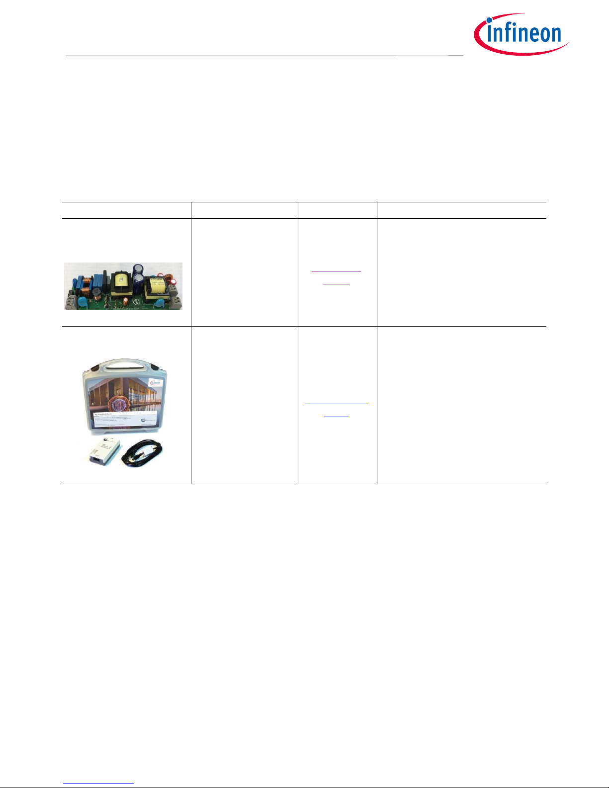
Name Description Ordering Link Ordering Content
XDPL8220 Reference
Board
XDPL8220 reference
board for LED lighting
XDPL8220-
Demo
• XDPL8220 Reference Board
Driver for LED lighting
• Programming Cable
To connect the XDPL8220
reference board with the .dp
Interface Gen2
.dp Interface Gen2
Interface to control
XDPL8220 from
PC/Notebook
IF-BOARD.DP-
GEN2
• .dp Interface Gen2
Interface for programming the
XDPL8220 digital controller
• USB Cable
To connect the .dp Interface Gen2
with PC
Page 3

Application Note 3 Revision 1.0
2016-11-01
Getting Started with the XDPL8220 Reference Board Using .dp Vision Software
1.2 Hardware Connection
After the required hardware tools are available, please follow the steps below to make the correct hardware
connection:
• Connect the .dp Interface Gen2 with the USB Cable to Notebook/PC
Figure 1 Connection from .dp Interface Gen2 to Notebook
Note: The detection of the .dp Interface Gen2 sometimes fails on USB3.0 ports. Therefore the use of a
USB2.0 port is recommended (which can be provided by an external USB2.0 hub if the machine
offers USB3.0 ports only).
• Connect the .dp Interface Gen2 with the Programming Cable to the XDPL8220 Reference Board
Figure 2 .dp Interface Gen2 Connection
Note: Please ensure that the connector of the Programming Cable is plugged in correctly: the red wire
indicates the Pin 1 and should be connected to the Pin Vcc on the XDPL8220 Reference Board.
USB
Cable
To
Notebook
Page 4

Application Note 4 Revision 1.0
2016-11-01
Getting Started with the XDPL8220 Reference Board Using .dp Vision Software
Figure 3 Connection from .dp Interface Gen2 to the XDPL8220 Reference Board
• Connect the XDPL8220 Reference Board to LED load
• Optional: Connect an 0-10V analog dimmer/PWM dimming signal to the XDPL8220 Reference Board
Attention: If an analog/PWM dimmer is not connected, with the default parameters (dim-to-off
disabled, dimming curve inverted) burned in XDPL8220, the reference board will output the
minimum current. For more information, please refer to the CSV file description [3].
Figure 4 Connection from the XDPL8220 Reference Board to LED Load and Dimmer
Programming
Interface
+ Vcc
UART
GND
To LED Load
Dimming
Interface
+
ە
+
ە
Page 5

Application Note 5 Revision 1.0
2016-11-01
Getting Started with the XDPL8220 Reference Board Using .dp Vision Software
• Connect the AC/DC power supply to the XDPL8220 Reference Board
Figure 5 Connection of AC/DC Power Supply
Attention: Please note that when the AC/DC is supplied to the XDPL8220 Reference Board before the
successful connection establishment from .dp Vision to the controller XDPL8220, the board will
operate with the already burned parameters. If the AC/DC is supplied after the successful
connection from .dp Vision to XDPL8220, the board will not operate and wait for the start
command (Test Configuration Set) from .dp Vision.
N
L
PE
AC/DC Input
Page 6

Application Note 6 Revision 1.0
2016-11-01
Getting Started with the XDPL8220 Reference Board Using .dp Vision Software
2 Software
2.1 Required Software Tools
The required software tools are listed in the following Table 2. Please download all the software tools with the
latest version.
Table 2 Required Software Tools for Getting Started
Name Description Download Link Download Content
.dp Vision
Graphic User interface
(GUI) for programming the
parameters of the digital
controller XDPL8220
.dp Vision
• .dp Vision installer (*.msi)
XDPL8220 Parameters CSV
File
XDPL8220 parameters
configuration file which is
opened by .dp Vision
all documents
are in
XDPL8220
project addon
installer
• XDPL8220 parameters
configuration file (*.csv)
• XDPL8220 image files
(*.png)
• XDPL8220 documentation
files (datasheet [1], board
description [2] , CSV file
description [3] and design
guide [4])
• XDPL8220 System
simulation & Design
Creation Tool
• .dp Interface Gen2
Firmware
XDPL8220 Image Files
Image files which explain
XDPL8220 parameters in
the .dp Vision. They are
mandotary to open the CSV
file in the .dp Vision.
XDPL8220 Documentation
Files
Datasheet [1], XDPL8220
board description [2], CSV
file description [3] and
design guide [4].
XDP8220 System simulation &
Design Creation Tool
Simulation and design tool
which helps customers to
develop their own designs
using XDPL8220
.dp Interface Gen2 Firmware
Firmware for .dp Interface
Gen2 to connect with
XDPL8220
Note: Please make sure that the latest version of all software is downloaded or .dp Vision will show error
messages.
Page 7

Application Note 7 Revision 1.0
2016-11-01
Getting Started with the XDPL8220 Reference Board Using .dp Vision Software
2.2 Software Installation
After the required software tools are downloaded, please follow the steps below to make the correct software
installation.
• Install first the .dp Vision software.
• After the .dp Vision is successfully installed, please install the project addon.
• After the .dp Vision and project addon are successfully installed, four sub folders are created under the “.dp
Vision” folder as shown in the following Figure 6:
Figure 6 Four Sub-folders Under .dp Vision
Note: Please use the shortcut generated on the desktop to access to these folders quickly!
• In the “Documents” folder you will find all the related documentation like datasheet, board description, CSV
file description and Design guide.
Attention: Please make sure that before getting started to operate the XDPL8220 reference board,
read the “XDPL8220 Board Description” thoroughly. A wrong operation of the reference board
could be dangerous to health and even to life!
• In the “DpIfGen2_FW” folder, the firmware of the interface board .dp Interface Gen2 is stored.
Attention: Please make sure that the firmware version of the interface board for XDPL8220 has
always a format of “dpIfGen2_Rev2-x-x.hex”. If the firmware version has a format of
“dpIfGen2_Rev1-x-x.hex” (f.g. for XDPL8105), please update if first or it will show error
message when connecting to XDPL8220.
• In the “Images” folder, the images related to the XDPL8220 parameters CSV file are stored.
Attention: Please make sure that the all necessary images are stored in this folder. If any image is
missing, the CSV file will not be opened by the .dp Vision and an error message will show.
• In the “Parameters” folder, the XDPL8220 parameters CSV file is stored.
Page 8

Application Note 8 Revision 1.0
2016-11-01
Getting Started with the XDPL8220 Reference Board Using .dp Vision Software
3 Getting Started
After the correct hardware connection and software installation, please follow the steps below to get started
with the operation of the XDPL8220 reference board and parameterization.
• Start the .dp Vision program by clicking the shortcut “.dp Vision” on the desktop as the following Figure 7
shows.
Figure 7 Starting .dp Vision
Attention: During the program startup, if the system shows there is a newer version of .dp Vision,
please kindly follow the procedures and update it accordingly.
• Open the XDPL8220 parameters configuration file (*.csv) in the folder …\Infineon Technologies AG\.dp
vision\Parameters as shown in the following
Figure 8 Open the CSV File
Select XDPL8220
configuration CSV file to
open
Page 9

Application Note 9 Revision 1.0
2016-11-01
Getting Started with the XDPL8220 Reference Board Using .dp Vision Software
• After opening the parameter csv file, a list of XDPL8220 configurable parameters will shown (see the box on
the left in Figure 9). These values can be then modified by users and will turn blue.
Attention: .dpVision will check the plausibility of the parameters values which are input by the user.
If any value violates the limits, the value will turn red and an error message will appear in the
message bar as shown in Figure 9. The limits may also be dependent on other user inputs.
Users are not allowed to save, test or burn the configuration if there is error detected.
Figure 9 Changing Parameter Values in .dp Vision
There are 2 options available to configure the IC based on the parameter values in .dp Vision.
• Burn Configuration
As the XDPL8220 chip on the 50W reference design PCB was already permanently burned with a first full set of
parameters in its one time programmable (OTP) memory space, any parameter value change using this option
is considered as parameter patching. The OTP memory space which is dedicated for patching or burning the
parameter value change has a memory size of 274 words.
Each time when the burn configuration function is executed, it will detect if there is parameter value difference
between the saved configuration file and the target XDPL8220. If there is difference detected, each burn
configuration will consume minimum 3 words depends on how many parameters need to be patched.
However, the process will be aborted if it consumes more memory space than what is remaining in the target
IC. As a result, the user will have to replace the target IC with a new XDPL8220 chip, in order to burn the
configuration.
Table 3 below shows the recommended procedures of using burn configuration function in .dp Vision to patch
the parameter into the OTP memory.
List of configurable
parameters
Message Bar
Page 10

Application Note 10 Revision 1.0
2016-11-01
Getting Started with the XDPL8220 Reference Board Using .dp Vision Software
Table 3 Burn Configuration procedures
Step Instruction
I Open configuration file (see example in Figure 9)
II If necessary, change any parameter value then press [File] >> [Save] or [File] >> [Save as], to save
the configuration file. Otherwise, proceed to step III
III Ensure that the primary supply voltage (e.g AC input) to the board is switched off or
disconnected and the hardware connection for configuration is ok based on Figure 2 and Figure
3
IV
Press to supply power and establish connection to the target XDPL8220. After this step,
XDPL8220 will be in configuration mode and the device status should change to .
V
Press to burn configuration into target XDPL8220
After this step, you should see a pop-up window, which is similar to one of these below.
VI Press “Proceed” or “Yes” to burn the configuration
After this step, you should see a pop up window which shows the burning is successful.
VII Press “OK” on the pop up window then disconnect the programming cable from board
connector and test the application, if needed.
• Test Configuration
This function will download the parameter values from the list in .dp Vision into the XDPL8220 RAM memory
space and it will then be followed by an automatic IC startup for application testing with the new configuration.
Unlike using the burn configuration, parameters configuration with this option is not permanent because the
loaded RAM content will be lost once the IC supply voltage is turned off or the IC restarts due to certain
protection. The advantage of using this option is it does not consume OTP memory space, thus there is no limit
on the amount of parameter value changes.
OR
Page 11

Application Note 11 Revision 1.0
2016-11-01
Getting Started with the XDPL8220 Reference Board Using .dp Vision Software
Table 4 below shows the recommended procedures of using test configuration function in .dp Vision to load
the new parameter values in the RAM and test the application with the new configuration.
Table 4 Test Configuration procedures
Step Instruction
I Open configuration file and change parameter value (see example in Figure 9)
II Ensure that the primary supply voltage (e.g AC input) to the board is switched off and the
hardware connection for configuration is ok based on Figure 2 and Figure 3.
III
Press to supply power and establish connection to the target XDPL8220. After this step,
XDPL8220 will be in configuration mode and the device status should change to .
IV Ensure LED output is connected to the board and switch on AC input (e.g. 230VAC).
After this step, the board does not startup because XDPL8220 is still in configuration mode.
V
Press to test configuration with target XDPL8220
After this step, the IC will automatically start up with the new configuration and you should see
a pop up window like below:
VI Press “OK” on the pop up window.
VII Repeat the steps to test another configuration change. Otherwise, turn off the AC input and
disconnect the programming cable from board connector.
Note: If there is any error encountered in between step I to VII, please kindly refer to the message bar of
.dp Vision for the error message. For more details, please kindly refer to the .dp Vision user manual
[5].
Page 12

Application Note 12 Revision 1.0
2016-11-01
Getting Started with the XDPL8220 Reference Board Using .dp Vision Software
[1] XDPL8220 Target Data Sheet
[2] XDPL8220 U50W Reference Board Description
[3] XDPL8220 50W CSV File Description
[4] XDPL8220 Design Guide
[5] .dp Interface Gen2 User Manual
Page 13

Application Note 13 Revision 1.0
2016-11-01
Getting Started with the XDPL8220 Reference Board Using .dp Vision Software
Revision History
Major changes since the last revision
Page or Reference Description of change
All First Release
Page 14

Published by
Infineon Technologies AG
81726 Munich, Germany
© 2017 Infineon Technologies AG.
All Rights Reserved.
Do you have a question about this
document?
Email: erratum@infineon.com
Document reference
IMPORTANT NOTICE
The information contained in this application note
is given as a hint for the implementation of the
product only and shall in no event be regarded as a
description or warranty of a certain functionality,
condition or quality of the product. Before
implementation of the product, the recipient of this
application note must verify any function and other
technical information given herein in the real
application. Infineon Technologies hereby
disclaims any and all warranties and liabilities of
any kind (including without limitation warranties of
non-infringement of intellectual property rights of
any third party) with respect to any and all
information given in this application note.
The data contained in this document is exclusively
intended for technically trained staff. It is the
responsibility of customer’s technical departments
to evaluate the suitability of the product for the
intended application and the completeness of the
product information given in this document with
respect to such application.
For further information on the product, technology,
delivery terms and conditions and prices please
contact your nearest Infineon Technologies office
(www.infineon.com).
WARNINGS
Due to technical requirements products may
contain dangerous substances. For information on
the types in question please contact your nearest
Infineon Technologies office.
Except as otherwise explicitly approved by Infineon
Technologies in a written document signed by
authorized representatives of Infineon
Technologies, Infineon Technologies’ products may
not be used in any applications where a failure of
the product or any consequences of the use thereof
can reasonably be expected to result in personal
injury.
Trademarks of Infineon Technologies AG
µHVICҹ, µIPMҹ, µPFCҹ, AU-
ConvertIRҹ, AURIXҹ, C166ҹ, CanPAKҹ, CIPOSҹ, CIPURSEҹ, CoolDPҹ, CoolGaNҹ, COOLiRҹ, CoolMOSҹ, CoolSETҹ, CoolSiCҹ,
DAVEҹ, DI-POLҹ, DirectFETҹ, DrBladeҹ, EasyPIMҹ, EconoBRIDGEҹ, EconoDUALҹ, EconoPACKҹ, EconoPIMҹ, EiceDRIVERҹ, eupecҹ, F
COSҹ, GaNpowIRҹ,
HEXFETҹ, HITFETҹ, HybridPACKҹ, iMOTIONҹ, IRAMҹ, ISOFACEҹ, IsoPACKҹ, LEDrivIRҹ, LITIXҹ, MIPAQҹ, ModSTACKҹ, my-
dҹ, NovalithICҹ, OPTIGAҹ,
OptiMOSҹ, ORIGAҹ, PowIRaudioҹ, PowIRStageҹ, PrimePACKҹ, PrimeSTACKҹ, PROFETҹ, PRO-SILҹ, RASICҹ, REAL3ҹ,
SmartLEWISҹ, SOLID FLASHҹ,
SPOCҹ, StrongIRFETҹ, SupIRBuckҹ, TEMPFETҹ, TRENCHSTOPҹ, TriCoreҹ, UHVICҹ, XHPҹ, XMCҹ
Trademarks updated November 2015
Other Trademarks
All referenced product or service names and trademarks are the property of their respective owners.
Edition 2016-11-01<yyyy-mm-dd>
AN_GS_201611_PL21_003
 Loading...