

Preliminary Data Sheet
FEATURES
Integrated Beam Splitter
•
• Bi-Directional Transmission in a single optical
window
Single fiber solution, singlemode fiber pigtail
•
with different connector options
Data rate up to 155 Mbit/s
•
FP Laser Diode with Multi-Quantum Well
•
structure, wavelength 1310 nm
• Class 1 Laser Product
Incorporated laser driv er and PIN-TIA Receiver
•
with post-amplifier
• 2x5 Small Form Factor Package with
Multisource Footprint
*) Ordering Information
V23870-A211x-xx00
(*)
Bi-Directional Pigtail SFF Transceiver
155 Mb/s, 1310 nm Tx / 1310 nm Rx
Absolute Maximum Ratings
Operating case t emperature
V23870-A2111-xx00 ....................... 0 to 70 °C
V23870-A2112-xx00 .................... -40 to 85 °C
Storage Ambient Temperature ................. -40 to 85 °C
Supply voltage .................................................. 3.53 V
Soldering Cond i tions Temp/Time
Iron Soldering only .................... 400 °C / 10 s
V23870 - A211x - xx00
Average Launched Power:
2: -8 ... -13 dBm
Temperature Range:
1: 0 ... +70 °C
2: -40 ... +85 °C
Connector:
A: Pigtail Only
B: SC
C: SC/APC 8°
F: MU
H: MU-J
K: LC
Coupling:
(Tx/Rx, Signal Detect)
1: AC/AC, PECL SD
2: DC/DC, PECL SD
5: AC/AC, TTL SD
6: DC/DC, TTL SD
Fiber Optics
JULY 2002
DESCRIPTION
The Infineon BIDI® transceiver – p art of Infineon’s Small Form Factor transceiver family – is based on the Physical
Medium Depend (PMD) sublayer and baseband medium.
Infineon's BIDI-TRX is designed to handl e multiple data rates and can be desig ned into Fast Ethernet, FDDI, Fiber
Channel, ATM-155, SDH STM-1, SONET OC-3, CCTV and other applications as well as different FTTx
applications according to the 100 Mb ps EFM standard (IEE E 802.3ah). It is suitable for both, short h aul
applications and distances of 20 km and beyond.
The appropriate fiber optic cable is the 9µm singlemode fiber pigtail with different connector options.
The Infineon BIDI transceiver is a single unit comprised of a transmitter, a receiver, WDM filter or beam spl i tter,
and a singlemode fiber pigtail. This design frees the customer from many alignment and PC board layout
concerns.
This transceiver operates at 155Mb/s from a single power supply (+3.3 V). The full differential dat a inputs and
outputs are PECL and LVPECL compatible.
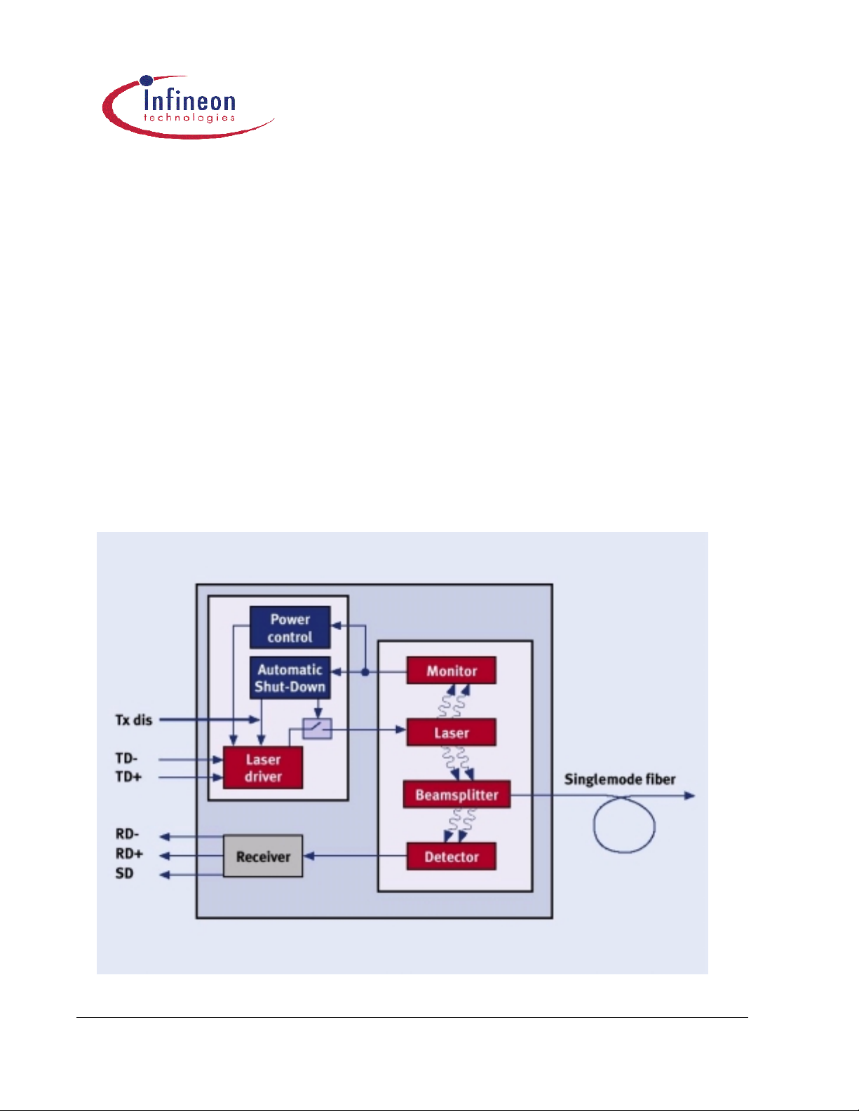
Functional Description of 2x5 Pin Row Transceiver
This transceiver is designed to transmit and receive serial data via a singlemode cable.
Functional Diagram
Fiber Optics 2
V23870-A2111/2-xx00 BIDI Pigtail SFF transceiver
The receiver component converts the optical serial data into PECL compatible electrical data (RD and RDnot). The
Signal Detect (SD, ac ti v e hig h) shows whether an optica l sig nal is prese nt.
The transmitter converts PECL compatible electrical serial data (TD and TDnot) into optical serial data. Data lines
are differentially 100Ω terminated.
The transmitter contains a laser dr iver circuit that dri ve s the modulation and bias current of the laser diode. The
currents are controlled by a power control circuit to guarantee constant output power of the laser over temperature
and aging.
The power control uses the output of the monitor PIN diode ( mechanically built into the laser couplin g unit) as a
controlling signal, to prevent the laser power from exce eding the operating li mits.
Single fault condition is ensured by means of an integrated automatic shutdown circuit that disables the laser
when it detects laser fault to guar antee the laser Eye Safety.
The transceiver contains a supervisory circuit to control the power supply. This circuit makes an internal reset
signal whenever the supply voltage drops below the reset threshold. It keeps the reset signal active for at least
140 milliseconds after the voltage has risen above the reset threshold. During this time the laser is inactive.
The laser can be d i sabled by the TxDi s input.
Technical Data
The electro-optical characteristics described in the following tables are valid only for use under the recommended
operating conditions.
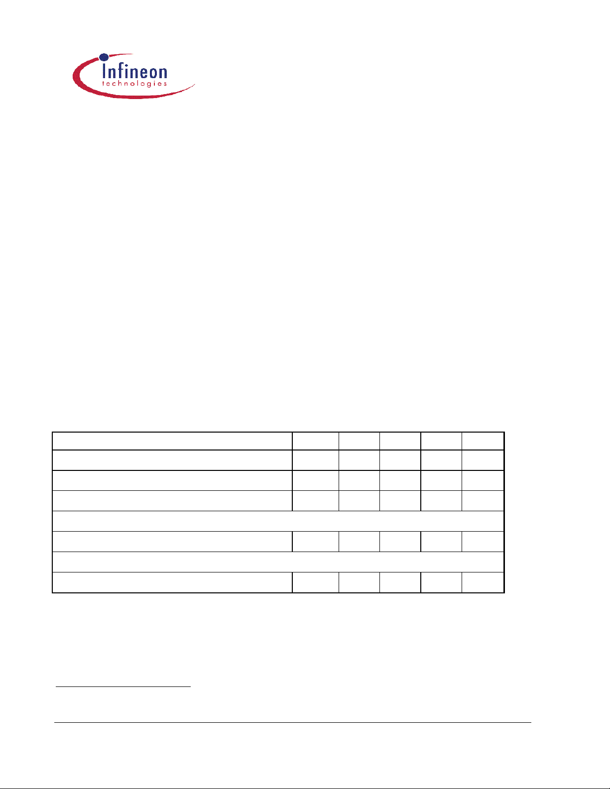
Recommended Operating Condi ti ons Symbol Min. Typ. Max. Unit
Operating Tem perature Range at Case1 T
Operating Tem perature Range at Case2 T
Power Supply Voltage
0 +70 °C
C
-40 +85 °C
C
V
3.1 3.3 3.53 V
CC-VEE
Transmitter
Data Input Differential Voltage V
250 1600 mV
DIFF
Receiver
Input Center Wavelength
λ
1500 1600 nm
C
1
For V23870-A2111-xx00
2
For V23870-A2112-xx00
Fiber Optics 3
V23870-A2111/2-xx00 BIDI Pigtail SFF transceiver

Transmitter
Average Launched Power P
Emission wavelength center of range3
Spectral bandwidth (RMS) σ
Temperature co efficient of emission wavelength
Symbol Min. Typ. Max. Unit
-13 -8 dBm
out,max
λ
λ
∆λ
(T) 0.5 nm/K
1270 1310 1350 nm
3.0 nm
Extinction Ratio (Dynamic) ER 8.5 dB
Jitter (pkpk) JPP 1 ns
Rise Time (20% - 80%)4
Fall Time (20% - 80%)5
tR
tF
2.5 ns
2.5 ns
Eye diagram ITU G.957 mask pattern
RIN Noise RIN -120 dB/√Hz
Reset Threshold5 V
Reset Timeout5
Power on Delay t
Shut Off Time for TxDis t
2.5 2.75 2.99 V
TH
t
140 240 560 ms
RES
PWR_ON
6 ms
DIS
88 111 140 ms
Max Tx Supply Current ITX 90 135 mA
3
P
= P
opt
4
Rise and fall times are measured with the OC-3 filter ON
5
Laser power is shut down if power supply is below VTH and switch on if power supply is above VTH after t
out,max
at T=25°C
Fiber Optics 4
.
RES
V23870-A2111/2-xx00 BIDI Pigtail SFF transceiver

Receiver
Symbol Min. Typ. Max. Unit
Receiving wavelength center of range6 λR 1270 1310 1350 nm
Sensitivity (Average Power)7 P
Saturation (Average Power) P
Signal Detect Ass e rt Leve l8 P
Signal Detect Deassert Level9 P
Signal Detect Hy ste r es is P
Signal Detect Ass e rt Time t
Signal Detect Deassert Time t
Data Output Differential Voltage10 V
-21 dBm
IN
-3.0 dBm
SAT
-22 dBm
SDA
-31 dBm
SDD
-
SDA
P
SDD
100 µs
ASS
350 µs
DAS
DIFF
0.5 4 6 dB
0.4 0.8 1.0 V
Rise/Fall Time tR; tF 1.5 ns
Max Rx Supply Cur r ent11 I
60 130 mA
RX
Module Electro-Optical Characte ristics
Symbol Min. Typ. Max. Unit
Optical Isolat ion12 ORL 14 dB
6
P
= P
opt
7
Minimum average optical power at which the BER is less than1x10E–10. Measured with a 1023 –1 NRZ PRBS as recommended by ANSI
T1E1.2, SONET OC-3, and ITU G.957.
8
An increase in optical power above the specified level will cause the SIGNAL DETECT output to switch from a Low state to a High state.
9
A decrease in optical power below the specified level will cause the SIGNAL DETECT to change from a High state to a Low state.
10
AC/AC for data. Load 50Ω to GND or 100Ω differential. For dynamic measurement a tolerance of 50mV should be added.
11
Supply current excluding Rx output load.
12
Source wavelength is 1550 nm, BiDi Tx and Rx is Off
out,max
at T=25°C
Fiber Optics 5
V23870-A2111/2-xx00 BIDI Pigtail SFF transceiver

Fiber Data
The mechanical fiber chara cteri st ics are des cri bed in the follow in g table .
Fiber Characteristics Min. Typ. Max. Unit
Mode Field Diameter 8 9 10 µm
Cladding Diameter 123 125 127 µm
Mode Field/Cladding Concentricity Error 1 µm
Cladding Non-circularity 2 %
Mode Field Non-circularity 6 nm
Cut off W avelength 1270 nm
Jacket Diameter 0.8 1 mm
Bending Radius 30 mm
Tensile Strength Fiber Case 5 N
Length 0.8 1.2 m
Fiber Optics 6
V23870-A2111/2-xx00 BIDI Pigtail SFF transceiver

Pin Description
Pin Name
V
EEr
V
CCr
SD Signal Detect see options
Level/ Logic Pin# Description
Receiver Signal Ground N/A 1
Receiver Power Supply N/A 2
3 Normal Operation: Logic “1” Output, represents
on page 1
that light is pres ent at receiver input
Fault Conditio n: Logic “0” Output
Recommended Termination of 510 Ω to Vee
PECL
RD– Received Data Out Not PECL 4
RD+ Received Data Out PECL 5
V
N/A 6 Transmitter Power Supply
CCt
V
N/A 7 Transmitter Signal Ground
EEt
TxDis Transmitter
Disable/Enable
TTL-Input 8 A low/o pen sign al swit che s th e laser on.
A high signal switches the laser of f.
TD+ Transmit Data PECL 9 Transmitter Data In
TD– Transmit Data Not PECL 10 Transmitter Data In Not
MS Mounting Studs N/A MS1
HL Housing Leads N/A T1
Mounting Studs are provided for transceiver
MS2
mechanical atta chm en t to the
circuit board.
The transceiver Housing Leads ar e provided for
additional signal grounding. The
T2
holes in the circuit board must be incl uded and
T3
be tied to signal ground.
T4
for
r
Fiber Optics 7
V23870-A2111/2-xx00 BIDI Pigtail SFF transceiver

Technical drawings
49.01
1.930
22.27
.877
5.15
.203
+10
+.394
-.000
13.50
.531
12
.472
TEMPERATURE
MEASUREMENT
LOCATION
0
13.50
.531
9.71
.382
1.40
.055
.118
0.38
.015
4.56
.180
3.10
.122
3
0.25
2X
.010
1.07
.042
10.16
.400
20X
0.81
.032
7.11
.280
3.92
.154
17.79
.700
20.19
.795
1.78
.070
1.84
.072
NOTES:
1. FIBER AND CONNECTOR NOT SHOWN.
2. REFER TO PACKAGE OUTLINE OF THE SMALL
FORM FACTOR TRANSCEIVER MULTISOURCE
AGREEMENT FOR DIMENSIONS NOT SHOWN.
Fiber Optics 8
13.34
.525
21.34
.840
23.88
.940
15.75
.620
FRONT OF BEZEL
Circuit Board Layout
Recommended PCB Thickness 0.1 (2.54) max.
V23870-A2111/2-xx00 BIDI Pigtail SFF transceiver

EYE SAFETY
This laser based singlemode transceiver is a Class 1 product. It comp lies with IEC 60825-1 and FDA 21 CFR
1040.10 and 1040.11. To meet laser safety requirements the transceiver shall be operated within the maximum
operating limits.
Caution
All adjustments have been made at the factory prior to shipment of the devices. No maintenance or
alteration to the device is required.
Tampering with or modifying the performance of the device will result in voided product warranty.
Note: Failure to adher e to the above restrictions could res ul t in a modification that is conside red an act of
“manufacturing,” and will require, under law, recertification of the modified product with the U.S. Food and Drug
Administration (ref. 21 CFR 1040.10 (i)).
APPLICATION NOTES
Transceiver Assembly/Soldering
Recommended requireme nts
avoid temperatures on fiber and connector above 85°C
•
only iron soldering permitted
•
single pin or simultaneous pin soldering valid
•
Type Conditions Standard
Iron - soldering iron tip temp. < 400 °C
solder time < 10 sec
IEC 68 2-20 test Tb, methode 2
Fiber Optics 9
V23870-A2111/2-xx00 BIDI Pigtail SFF transceiver

AC/AC coupling
Vcc
3.3V
L1
L2
C1
RxVcc (2)TxVcc (6)
Laser
Driver
Limiting
Amplifier
SFF Transceiver
C3
C2
100
Ohms
TxVee (7)
TD+ (9)
TD- (10)
TxDis (8)
SD (3)
Rd- (4)
Rd+ (5)
RxVee (1)
R7
SD
R5
Vcc
SerDes
3.3V
R1 R2
R4R3
R6
Vcc
Ser Data
Out+
Ser Data
Out-
Ser Data In-
Ser Data In+
ECL/PECL
Driver
Serializer/
Deserializer
Receiver
L1, L2: 1...4.7 µH
C1, C2, C3: 4.7...10 µF
R1, R2: biasing of outputs depending on Serializer
R3, R4: 127 Ohms
R5, R6: 80 Ohms
R7: 510 Ohms for PECL signal detect, open for TTL
Place R1/2/3/4/5/6 as close to SerDes chip as possible
Fiber Optics 10
V23870-A2111/2-xx00 BIDI Pigtail SFF transceiver

DC/DC coupling
Vcc
3.3V
L1
L2
C1
RxVcc (2)TxVcc (6)
Laser
Driver
Limiting
Amplifier
SFF Transceiver
C3
C2
TxVee (7)
TD+ (9)
TD- (10)
TxDis (8)
SD (3)
Rd- (4)
Rd+ (5)
RxVee (1)
R10
R2
SD
R8
R7R6
R9
R3
C6
C7
C4
C5
Vcc
SerDes
3.3V
R4 R5
R1
Vcc
Ser Data
Out+
Ser Data
Out-
Ser Data In-
Ser Data In+
ECL/PECL
Driver
Serializer/
Deserializer
Receiver
L1, L2: 1...4.7 µH
C1, C2, C3: 4.7.. .10 µF
C4, C5, C6, C7:100 nF
R1: 100 Ohms
R2, R3: 15 0 Ohms
R4, R5: biasing of outputs depending on Serializer
R6, R7: 12 7 Ohms
R8, R9: 80 Ohms
R10: 510 Ohms for PECL signal detect, open for TTL
Place R1/4/5 as close to SerDes as possible
Place R2/3 as close to transceiver as possible
Fiber Optics 11
V23870-A2111/2-xx00 BIDI Pigtail SFF transceiver
 Loading...