

Page 1

Application Note 1 Rev. 1.1
www.infineon.com/embeddedpower 2020-12-08
Z8F56887800
FAQ Application Note for TLE986xQX,
TLE987xQX
Frequently Asked Questions and Application Hints
About this document
Scope and purpose
This Application Note is intended to provide helpful suggestions and hints how to set up and handle specific
modules and functionalities which are not subject of the Users Manual or Data Sheet and might be interesting
for end users. It is organized in a frequently asked question style and doesn’t follow any specific order.
Note: The following information is given as a hint for the implementation of the device only and shall not
be regarded as a description or warranty of a certain functionality, condition or quality of the device.
Intended audience
This template is intended for Customer and FAE to document frequently asked question and answers for the
embedded Power IC, TLE986xQX and TLE987xQX device family.
Page 2

FAQ Application Note for TLE986xQX, TLE987xQX
Z8F56887800
Table of Contents
About this document . . . . . . . . . . . . . . . . . . . . . . . . . . . . . . . . . . . . . . . . . . . . . . . . . . . . . . . . . . . . . . 1
Table of Contents . . . . . . . . . . . . . . . . . . . . . . . . . . . . . . . . . . . . . . . . . . . . . . . . . . . . . . . . . . . . . . . . . 2
1 Introduction . . . . . . . . . . . . . . . . . . . . . . . . . . . . . . . . . . . . . . . . . . . . . . . . . . . . . . . . . . . . . . . . . . . . . 1
2 Collection of Questions and Topics . . . . . . . . . . . . . . . . . . . . . . . . . . . . . . . . . . . . . . . . . . . . . . . . . . 1
3 GPIO Port Map and Alternate Functions . . . . . . . . . . . . . . . . . . . . . . . . . . . . . . . . . . . . . . . . . . . . . . 3
3.1 Description: GPIO Register description . . . . . . . . . . . . . . . . . . . . . . . . . . . . . . . . . . . . . . . . . . . . . . . . . . . . . . 3
3.2 Implementation: Alternate Function configuration example . . . . . . . . . . . . . . . . . . . . . . . . . . . . . . . . . . 3
3.3 Implementation: Port Map of Alternate Functions . . . . . . . . . . . . . . . . . . . . . . . . . . . . . . . . . . . . . . . . . . . . 3
4 SWD (Serial Wire Debug) Interface Circuitry . . . . . . . . . . . . . . . . . . . . . . . . . . . . . . . . . . . . . . . . . . 5
4.1 Description: SWD (Serial Wire Debug) Interface . . . . . . . . . . . . . . . . . . . . . . . . . . . . . . . . . . . . . . . . . . . . . . 5
4.2 Implementation: SWD Interface connection to TLE986x/ TLE987x . . . . . . . . . . . . . . . . . . . . . . . . . . . . . 5
5 Bootup Configuration . . . . . . . . . . . . . . . . . . . . . . . . . . . . . . . . . . . . . . . . . . . . . . . . . . . . . . . . . . . . . 6
5.1 Description: BSL Connection Window . . . . . . . . . . . . . . . . . . . . . . . . . . . . . . . . . . . . . . . . . . . . . . . . . . . . . . . 6
5.1.1 None-Activity-Counter - NAC . . . . . . . . . . . . . . . . . . . . . . . . . . . . . . . . . . . . . . . . . . . . . . . . . . . . . . . . . . . . . 6
5.1.2 Node Address - NAD . . . . . . . . . . . . . . . . . . . . . . . . . . . . . . . . . . . . . . . . . . . . . . . . . . . . . . . . . . . . . . . . . . . . . 7
5.1.3 LIN slope after NAC . . . . . . . . . . . . . . . . . . . . . . . . . . . . . . . . . . . . . . . . . . . . . . . . . . . . . . . . . . . . . . . . . . . . . . 7
5.2 Implementation: Write NAC NAD values to the correct position in Flash . . . . . . . . . . . . . . . . . . . . . . . . 8
6 Watchdog Handling WDT1 . . . . . . . . . . . . . . . . . . . . . . . . . . . . . . . . . . . . . . . . . . . . . . . . . . . . . . . . 10
6.1 Description: Window Watchdog Timer WDT1 . . . . . . . . . . . . . . . . . . . . . . . . . . . . . . . . . . . . . . . . . . . . . . . 10
6.2 Implementation: Watchdog Handling µVision 5 . . . . . . . . . . . . . . . . . . . . . . . . . . . . . . . . . . . . . . . . . . . . . 10
6.3 Implementation: WDT1 Hints . . . . . . . . . . . . . . . . . . . . . . . . . . . . . . . . . . . . . . . . . . . . . . . . . . . . . . . . . . . . . 11
6.3.1 Potential WDT1 Traps . . . . . . . . . . . . . . . . . . . . . . . . . . . . . . . . . . . . . . . . . . . . . . . . . . . . . . . . . . . . . . . . . . 11
6.3.2 Consequence . . . . . . . . . . . . . . . . . . . . . . . . . . . . . . . . . . . . . . . . . . . . . . . . . . . . . . . . . . . . . . . . . . . . . . . . . . 11
6.3.3 Root Cause . . . . . . . . . . . . . . . . . . . . . . . . . . . . . . . . . . . . . . . . . . . . . . . . . . . . . . . . . . . . . . . . . . . . . . . . . . . . 11
6.3.4 Solution: . . . . . . . . . . . . . . . . . . . . . . . . . . . . . . . . . . . . . . . . . . . . . . . . . . . . . . . . . . . . . . . . . . . . . . . . . . . . . . 11
7 Device state after system overtemperature . . . . . . . . . . . . . . . . . . . . . . . . . . . . . . . . . . . . . . . . . 12
7.1 Description: System overtemperature detection . . . . . . . . . . . . . . . . . . . . . . . . . . . . . . . . . . . . . . . . . . . . 12
7.2 Implementation: Cyclic wake period . . . . . . . . . . . . . . . . . . . . . . . . . . . . . . . . . . . . . . . . . . . . . . . . . . . . . . . 13
8 BEMF comparator demag-pulse filter . . . . . . . . . . . . . . . . . . . . . . . . . . . . . . . . . . . . . . . . . . . . . . . 14
8.1 Describtion: Demag-pulse filter . . . . . . . . . . . . . . . . . . . . . . . . . . . . . . . . . . . . . . . . . . . . . . . . . . . . . . . . . . . 14
8.2 Implementation: Demag-pulse filter output . . . . . . . . . . . . . . . . . . . . . . . . . . . . . . . . . . . . . . . . . . . . . . . . 14
9 VQFN vs TQFP package . . . . . . . . . . . . . . . . . . . . . . . . . . . . . . . . . . . . . . . . . . . . . . . . . . . . . . . . . . . 16
9.1 Implementation: Additional parameters and test conditions . . . . . . . . . . . . . . . . . . . . . . . . . . . . . . . . . 16
10 BDRV on-state vs off-state diagnosis . . . . . . . . . . . . . . . . . . . . . . . . . . . . . . . . . . . . . . . . . . . . . . . 17
10.1 Description: diagnosis features in the BDRV . . . . . . . . . . . . . . . . . . . . . . . . . . . . . . . . . . . . . . . . . . . . . . . . 17
10.1.1 On-state diagnosis . . . . . . . . . . . . . . . . . . . . . . . . . . . . . . . . . . . . . . . . . . . . . . . . . . . . . . . . . . . . . . . . . . . . . 17
10.1.2 Off-state diagnosis . . . . . . . . . . . . . . . . . . . . . . . . . . . . . . . . . . . . . . . . . . . . . . . . . . . . . . . . . . . . . . . . . . . . . 17
10.2 Implementation: Register settings and status registers . . . . . . . . . . . . . . . . . . . . . . . . . . . . . . . . . . . . . . 17
11 Internal voltage regulators . . . . . . . . . . . . . . . . . . . . . . . . . . . . . . . . . . . . . . . . . . . . . . . . . . . . . . . 18
11.1 Description: internal voltage generation . . . . . . . . . . . . . . . . . . . . . . . . . . . . . . . . . . . . . . . . . . . . . . . . . . . 18
12 ASIL rating of TLE986x/7x . . . . . . . . . . . . . . . . . . . . . . . . . . . . . . . . . . . . . . . . . . . . . . . . . . . . . . . . . 18
12.1 Description: Functional safety with TLE986x/7x . . . . . . . . . . . . . . . . . . . . . . . . . . . . . . . . . . . . . . . . . . . . . 18
Application Note 2 Rev. 1.1
2020-12-08
Page 3

FAQ Application Note for TLE986xQX, TLE987xQX
Z8F56887800
13 Power dissipation inside TLE986x/7 . . . . . . . . . . . . . . . . . . . . . . . . . . . . . . . . . . . . . . . . . . . . . . . . 18
14 Very high/low duty cycle PWM . . . . . . . . . . . . . . . . . . . . . . . . . . . . . . . . . . . . . . . . . . . . . . . . . . . . . 19
14.1 Description: CCU6 PWM generation . . . . . . . . . . . . . . . . . . . . . . . . . . . . . . . . . . . . . . . . . . . . . . . . . . . . . . . . 19
14.2 Implementation: 100% duty-cycle . . . . . . . . . . . . . . . . . . . . . . . . . . . . . . . . . . . . . . . . . . . . . . . . . . . . . . . . . 20
15 Revision History . . . . . . . . . . . . . . . . . . . . . . . . . . . . . . . . . . . . . . . . . . . . . . . . . . . . . . . . . . . . . . . . . 22
Application Note 3 Rev. 1.1
2020-12-08
Page 4

FAQ Application Note for TLE986xQX, TLE987xQX
Z8F56887800
Introduction
1 Introduction
This Application Note lists topics emerged from frequently asked questions of users or from changed user
requirements. Each topic is organized in three sections:
• Topic:
– Short description of the issue.
• Description:
– More details about the topic
• Implementation hint (optional):
– Instruction how to handle this topic
2 Collection of Questions and Topics
This chapter gives an overview of the collected Questions and Topics.
Table 1 Table of Questions
Topic Chapter Page
What PIN is connected to which peripheral?
GPIO Port Map and Alternate Functions
How to connect the Debug Interface?
SWD (Serial Wire Debug) Interface Circuitry
Why does the chip not start up, after reset?
Bootup Configuration
Why does the LIN slope change after a NAC?
Bootup Configuration
Why does the chip do resets every second?
Watchdog Handling WDT1
Does the NAC affect the LIN slope?
LIN slope after NAC
What state does the device enter after system overtemperature?
Device state after system overtemperature
What is the demagnetization filter and how does it work?
BEMF comparator demag-pulse filter
What is the difference between the VQFN and TQFP package variants?
VQFN vs TQFP package
Chapter 3 Page 3
Chapter 4 Page 5
Chapter 5 Page 6
Chapter 5 Page 7
Chapter 6 Page 10
Chapter 5 Page 7
Chapter 7 Page 12
Chapter 8 Page 14
Chapter 9 Page 16
What is the difference between the on and off-state diagnosis in the
bridge-driver module?
BDRV on-state vs off-state diagnosis
What can the internal voltage regulators be used for?
Internal voltage regulators
Which ASIL rating does the TLE9876x/7x have?
BEMF comparator demag-pulse filter
Application Note 1 Rev. 1.1
Chapter 10 Page 17
Chapter 11 Page 18
Chapter 12 Page 18
2020-12-08
Page 5

FAQ Application Note for TLE986xQX, TLE987xQX
Z8F56887800
Collection of Questions and Topics
Table 1 Table of Questions
Topic Chapter Page
How can the power dissipation inside the TLE986x/7x be calculated?
Power dissipation inside TLE986x/7
How can very high/low PWM duty cycles be acchieved?
Very high/low duty cycle PWM
Chapter 13 Page 18
Chapter 14 Page 19
Application Note 2 Rev. 1.1
2020-12-08
Page 6
FAQ Application Note for TLE986xQX, TLE987xQX
Z8F56887800
GPIO Port Map and Alternate Functions
3 GPIO Port Map and Alternate Functions
What PIN is connected to which peripheral?
The TLE986xQX and TLE987xQX have 15 port pins organized in three parallel ports: Port 0 (P0), Port 1 (P1) and
Port 2 (P2). Each port pin has a pair of internal pull-up and pull-down devices that can be individually enabled
or disabled. Either pull-up or pull-down devices can be enabled at a time, for a single port pin. P0 and P1 are
bidirectional and can be used as general purpose input/output (GPIO) or to perform alternate input/output
functions for the on-chip peripherals. When configured as an output, the open drain mode can be selected. On
Port 2 (P2) analog inputs are shared with general purpose input.
3.1 Description: GPIO Register description
Each port consists of 8-bit control and data registers. The registers are defined in Table 2.
Table 2 Port Register
Register Short Name Register Long Name Description
Px_DATA Port x Data Register x = {0,1,2}
Px_DIR Port x Direction Register x = {0,1,2}
Px_OD Port x Open Drain Control Register x = {0,1}
Px_PUDSEL Port x Pull-Up/Pull-Down Select Register x = {0,1,2}
Px_PUDEN Port x Pull-Up/Pull-Down Enable Register x = {0,1,2}
Px_ALTSEL0 Port x Alternate Select Register 0 x = {0,1}
Px_ALTSEL1 Port x Alternate Select Register 1 x = {0,1}
3.2 Implementation: Alternate Function configuration example
The ports P0 and P1 can be configured to four different output functions. The default configuration is the GPIO
function. The three remaining functions are alternate output functions.
The alternate output function selection is splitted in two bitfields (e.g. P1_ALTSEL0 and P1_ALTSEL1).
ALTSEL1 contains the most significant bit. ALTSEL0 contains the least significant bit. The given example code
shows how to configure these bitfields to connect UART2 module (TXD, RXD) with the GPIOs (P1.0, P1.1).
/* connect UART2 to GPIO */
/* set P1.1 to UART2_TXD: */
PORT->P1_DIR.bit.P1 = 1u; /* PORT P1.1 output configuration */
PORT->P1_ALTSEL0.bit.P1 = 1u; /* UART2_TXD alternate function 3 */
PORT->P1_ALTSEL1.bit.P1 = 1u; /* UART2_TXD alternate function 3 */
/* Set P1.2 to UART2_RXD: */
PORT->P1_DIR.bit.P2 = 0u; /* PORT P1.2 input configuration */
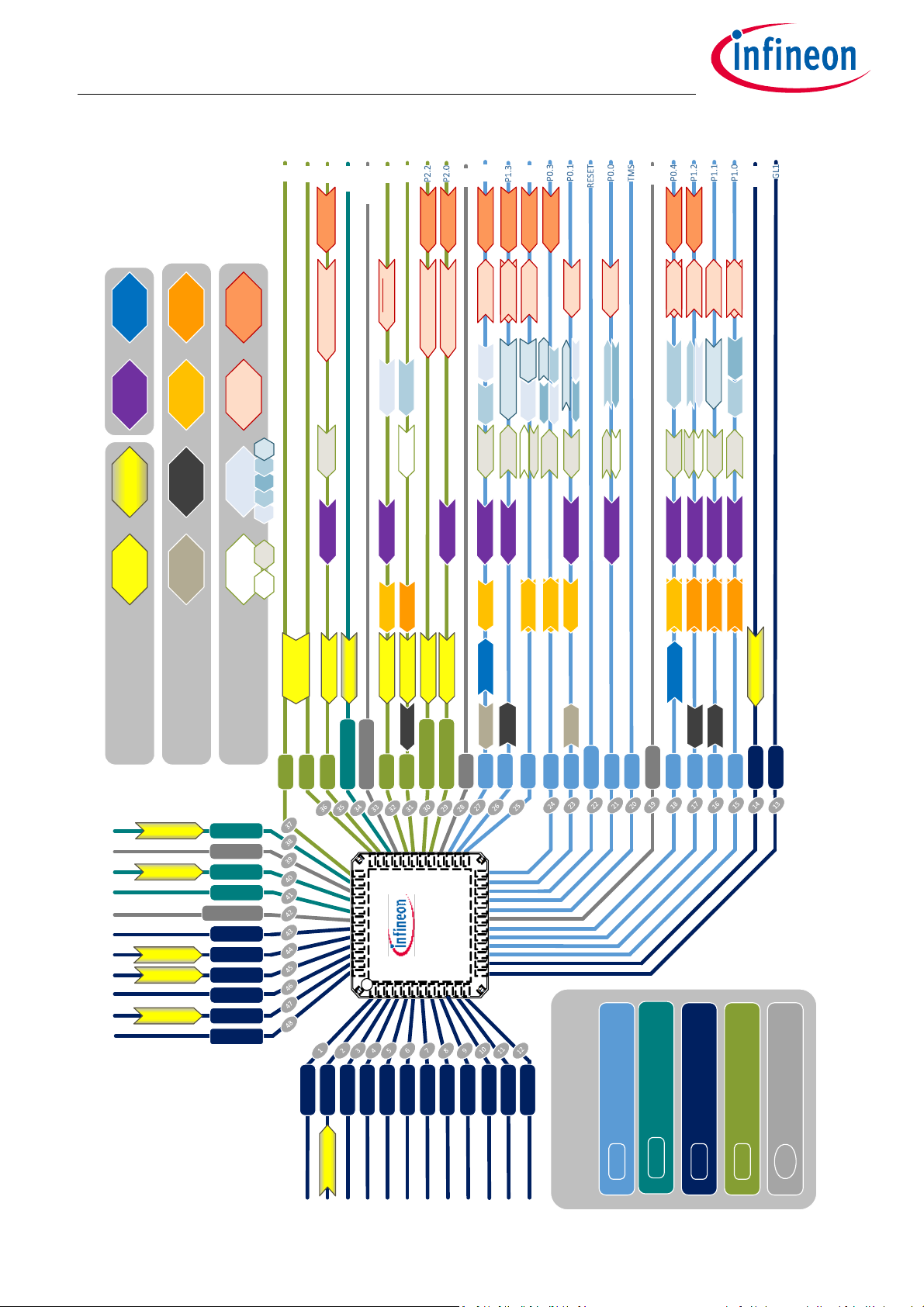
3.3 Implementation: Port Map of Alternate Functions
Graphical Portmap of Alternate Functions
Each pin is able to handle multiple purposes. Figure 1 shows the internal signals mapped to GPIOs. The arrow
boxes contain the signal names and indicate the data flow direction.
Application Note 3 Rev. 1.1
2020-12-08
Page 7
FAQ Application Note for TLE986xQX, TLE987xQX
Timer:
Analog Inputs:
Communication:
GND
P1.4
Legend
P0.2
OP1
P2.5
P2.4
GND_REF
VAREF
P2.3
OP2
MON
GND
TLE987xQX
EXINT1 _1
EXINT2 _3
ADC1 / CH0
ADC1 / CH3
ADC1 / CH4
ADC1 / CH2
ADC1 / CH1
CP1L
VCP
CP2H
CP2L
GL3
GL2
CP1H
VSD
VS
VDH
LIN
GND_LIN
T2EUDA
MRST_1_2
RXD
TXD
OP2
P2.3
GND_REF
P2.4
P2.5
P2.2/XTAL2
P2.0/XTAL1
P1.3
P0.2
P0.3
P0.0
P0.1
RESET
TMS
GND
P0.4
P1.2
P1.1
P1.0
MON
GL1
T2_0
T21_0
EXF21 _0
CAPINA
T6OUT
T4INA
T3OUT
T12HR_0
SL
GH1
SH1
GH2
SH2
GH3
GND
P1.4
VAREF
OP1
SH3
VDDEXT
VDDP
GND
VDDC
High Voltage IOs
VS
Input only PINs
P2.4
PIN numbers
1
5V PINs and GPIOs
P1.0
Internal LDOs
VDDC
ADC1 / CH5
ADC2 / CH6
ADC2 / CH1
ADC2 / CH2
ADC2 / CH3
ADC2 / CH4
ADC2 / CH5
ADC2 / CH6
ADC2 / CH8
T13HR_0
EXINT0 _2
T21EX_0
EXF2_0
COUT60_0
CCPOS2_1
CAPINB
CCPOS0_1
EXF21 _2
T6OUT
CCPOS1_1T21_2
EXINT2 _2
T3EUDA
T4EUDB
EXINT1 _2 EXF21 _3
T6EUDA
T21_1
EXINT1 _0
COUT61_0
TXD
T2INA
T21EX_3
CCPOS2_2
EXINT0 _1
COUT63_0
T3OUT
T6INB, T6EUDB
CCPOS0_2
EXF21_ 1
TXD
EXINT2 _1
T21EX_1
RXD
CCPOS1_2
MRST_1_3
T12HR_2, CC61_2
EXINT0 _0
CTRAP#_1, CC60_1T21EX_2
EXINT0 _3
T2EUDBMRST_1_1
EXINT1 _3
RXD
T3EUDB
MRST_2_1
T2_1
SCK_2
MTSR_2
MRST_2_0
MRST_1_0
SCK_1
MTSR_1
CC61_0
CTRAP#_0
CLKOUT_1
CLKOUT_0
COUT62_0
ADC1 ADC2
UART1 UART2
SSC1 SS C2
External
Interrupt
Timer 2x
GPT12 CCU6
SCU
Hall
Inputs
CCPOS1_0
CCPOS2_3
T13HR_2, CC62_2
CCPOS0_3
CC62_0
CC60_0
T5EUDA
T2INB
T6INA
T3INC
T4INC
T5INA
T4EUDA
T2 T3 T4 T5 T6
T2EX_1
T21T2
Z8F56887800
GPIO Port Map and Alternate Functions
Figure 1 Port Map of Alternate Functions
Application Note 4 Rev. 1.1
2020-12-08
Page 8
FAQ Application Note for TLE986xQX, TLE987xQX
TLE9879QX SWD Connector
PIN 40 VDDP PIN 1
PIN 20 TMS PIN 2
GND PIN 3, 5, 7, 9
PIN 21 P0.0 PIN 4
PIN 22 RESET PIN 10
Schematic Layout
PIN 1 PIN 2
Z8F56887800
SWD (Serial Wire Debug) Interface Circuitry
4 SWD (Serial Wire Debug) Interface Circuitry
How to connect the Debug Interface?
The Serial Wire Debug interface is used to download code to the embedded Power IC or to debug the chip. This
Topic explains how to implement the circuitry around the chip to achieve a successfull SWD connection.
4.1 Description: SWD (Serial Wire Debug) Interface
Serial Wire Debug (SWD) provides a debug port for severely pin limited packages, often the case for small
package microcontrollers but also complex ASICs where limiting pin-count is critical and can be the
controlling factor in device costs.
For SWD the TLE9879 uses the pins TMS (data) and P0.0 (clock). On the Evaluation boards, the signals are
routed through a 5x2 pinheader (SWD connector). The following Implementation explains the connection
between embedded Power IC and SWD Interface.
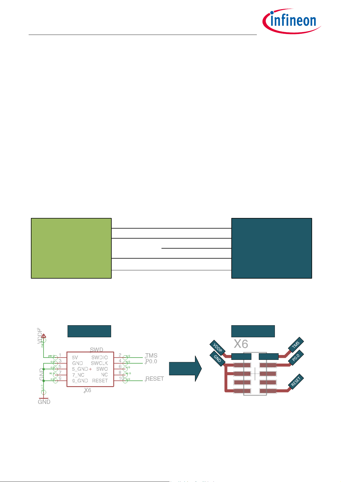
4.2 Implementation: SWD Interface connection to TLE986x/ TLE987x
The SWD Interface can be directly connected to the TLE987x and TLE986x family. The use of external pull up
or pull down resistors is not needed, due to internal pull down resistors. Figure 2 shows the interconnections
between TLE Device and and SWD Connector.
Figure 2 SWD Connection to the TLE987x and TLE986x Device
On TLE9879 and TLE9869 Evalkit SWD Interface PIN 9 is used to deactivate the onboard debugging circuit. For
a typical implementation this PIN is used as GND. The Pinout is shown in Figure 3.
Figure 3 SWD Interface implementation for application
Application Note 5 Rev. 1.1
2020-12-08
Page 9

FAQ Application Note for TLE986xQX, TLE987xQX
(NAC): None Activity Counter User Code: int main();
0ms...55ms
Powe r On Res et Enter User Mode
VS Voltage
Time
Z8F56887800
Bootup Configuration
5 Bootup Configuration
Why does the chip not start up, after reset?
Using a new device can cause issues, due to the device is not executing user code. This chapter explains how
to configure the chip to boot up and enter Users Code as expected.
5.1 Description: BSL Connection Window
After the reset PIN releases and some fundamental initializations of the device has been done, the BSL
connection acception window starts. The duration of this timing window is defined by the None-ActivityCounter (NAC). In this time period, the device can be programmed via LIN. After the NAC expires, the chip will
enter the user mode as shown in Figure 4.The following chapter provides some more inside view into the NAC
value.
Figure 4 Startup Procedure
5.1.1 None-Activity-Counter - NAC
The NAC timer is started during startup before the BSL mode, inside the firmware, starts. Once the NAC timer
has expired the boot-up process will be continued and the control of the device will be given to the user
application. The NAC is a value which will be defined by the user and stored inside the code flash. Usually the
NAC value is part of the user application which was downloaded before.
The NAC value is stored inside one byte. Only six bits of the NAC byte are defining the timeout value of the NAC.
The NAC value inside the NVM is secured by storeing it as a 1s-complement value in the following byte . Only if
the true NAC value and the complement NAC do match (means: not (true NAC) == complement NAC) the NAC
value is valid and the NAC timer will be activated during start-up. In case of an invalid value, i.e. like for an
erased flash where both bytes containing 0xFF, the NAC timer never expires, means the device will stay and
wait in BSL mode. This behavior is especially usefull for fresh devices, where no user application has been
downloaded to the device yet. Here the firmware will not branch into user mode, but instead it will stay in BSL
mode and keeps waiting for any BSL communication to download any user application into the flash.
The NAC value and its complement is stored at the following addresses inside the user accessible flash:
Table 3 Address of the NAC values inside flash
Address Usage
0x11000000 + (Total_Flash_Size - 0x1004) true NAC value
0x11000000 + (Total_Flash_Size - 0x1003) complement NAC value
The meaning of the NAC bits are listed in Table 4.
Application Note 6 Rev. 1.1
2020-12-08
Page 10

FAQ Application Note for TLE986xQX, TLE987xQX
Z8F56887800
Bootup Configuration
Table 4 NAC bit meaning
NAC Bit Usage
5..0 NAC expire value n, (n - 1) * 5ms, 0ms..55ms
0x00, 0x0D..0x3F: NAC never expires, device stays in BSL Mode, BSL mode is active
0x01: BSL mode is skipped, BSL mode deactivated
0x02..0x0C: NAC timeouts between 5ms..55ms, BSL mode is active
6
7 0b0: BSL interface selection Fast-LIN
A fresh device, or a completly ereased device always selects Fast-LIN as BSL interface and stays in BSL mode
during start-up.
5.1.2 Node Address - NAD
Reserved
0b1: BSL interface selection UART
The NAD is used for the BSL communication to select an individual node. The NAD is a 8 bit value, where only
the values 0x01 to 0xFF are valid, 0x00 is an invalid value. The value 0xFF acts as a broadcast, this means all
devices connected to the LIN line are addressed no matter which NAD value is programmed inside the device.
The broadcast can be used to establish a BSL connection to devices where the programmed NAD value is
unknown.
The NAD value is stored inside one byte inside the code flash area. The NAD value inside the NVM is secured by
storeing it as a 1s-complement value in the byte following the NAD value. Only if the true NAD value and the
complement NAD do match (means: not (true NAD) == complement NAD) the NAD value is valid otherwise the
device will only react on the default NAD value, which is 0x7F.
The NAD value and its complement is stored at the following addresses inside the user accessible flash:
Table 5 Address of the NAD values inside flash
Address Usage
0x11000000 + (Total_Flash_Size - 0x1002) true NAD value
0x11000000 + (Total_Flash_Size - 0x1001) complement NAD value
Table 6 NAD meaning
NAD Bit Usage
0x00 invalid NAD value, device will not react on these value, default NAD = 0x7F is used
0x01..0xFE valid NAD values
0xFF broadcast NAD, all devices will react on this value
5.1.3 LIN slope after NAC
If a NAC value is configured between 0x02 and 0x0C the device will automatically configure the LIN module for
fastLIN communication, a proprietary Infineon protocol passed on the LIN standard with a fixed baud rate of
115.2 kBaud. Due to the high baud rate the LIN slope will be automatically configured as well.
Application Note 7 Rev. 1.1
2020-12-08
Page 11

FAQ Application Note for TLE986xQX, TLE987xQX
Z8F56887800
Bootup Configuration
Table 7 LIN slope after NAC
Field Bit Value Describtion
LIN->CTRL_STS.SM 12:11 0b11 Flash Mode
If no BSL connection is performed during the duration of the NAC, the device will leave the BootROM and jump
directly into the user-code. If the user does not reconfigure the LIN in th user-code, the LIN slope will stay
configured to Flash Mode, resulting in higher EMI.
5.2 Implementation: Write NAC NAD values to the correct position in Flash
According to Chapter 5.1.1 and Chapter 5.1.2 the NAC and NAD Value have to be written to the correct
position in the Code Flash. Figure 5 shows the correct position for every Device of the TLE987x and TLE986x
embedded Power family.
The Implementation of the NAC-NAD value setting can be found in the Software Developement Kit based on
Keil µVision5.
Application Note 8 Rev. 1.1
2020-12-08
Page 12

FAQ Application Note for TLE986xQX, TLE987xQX
Sector
No.
Sector
Start Addr.
128K
Device
64K
Device
48K
Device
36K
Device
31 1101F000 Data Flash 1101EFFF NAD
30 1101E000 NAC / NAD 1101EFFE NAD
29 1101D000 1101EFFD NAC
28 1101C000 1101EFFC NAC
27 1101B000 1101EFFB
26 1101A000 1101EFFA
25 11019000 ·
24 11018000 ·
23 11017000 ·
22 11016000 1101E003
21 11015000 1101E002
20 11014000 1101E001
19 11013000 1101E000
18 11012000
17 11011000 1100EFFF NAD
16 11010000 1100EFFE NAD
15 1100F000 Data Flash 1100EFFD NAC
14 1100E000 NAC / NAD 1100EFFC NAC
13 1100D000 · Code Flash
12 1100C000
11 1100B000 Data Flash 1100AFFF NAD
10 1100A000 NAC / NAD 1100AFFE NAD
9 11009000 1100AFFD NAC
8 11008000 Data Flash 1100AFFC NAC
7 11007000 NAC / NAD · Code Flash
6 11006000
5 11005000 11007FFF NAD
4 11004000 11007FFE NAD
3 11003000 11007FFD NAC
2 11002000 11007FFC NAC
1 11001000 · Code Flash
0 11000000
TLE987xQX, TLE986xQX
Normal Code Flash
Z8F56887800
Bootup Configuration
Figure 5 Memory Map
The following lines of code are part of the files “system_TLE987x.c/...6x.c”. The defines can be found in
“TLE987x.h/...6x.h” and “tle_device.h”. The Code will also work “standalone”
#define ProgFlashSize (0x8000U) /*Flashsize for TLE9871/...61 */
#define ProgFlashSize (0xB000U) /*Flashsize for TLE9873QXW40 */
#define ProgFlashSize (0xF000U) /*Flashsize for TLE9877/...67 */
#define ProgFlashSize (0x1F000U) /*Flashsize for TLE9879/...69 */
Please, use only one of the definitions above, at a time. For example TLE9879(0x1F000U) for TLE9879 Evalkit.
#define NAD_NAC (0xFE01BA45u) /*Example: 4 bytes for NAC = 0x45u and NAD = 0x01u */
#define ProgFlashStart 0x11000000U) /*start address code flash*/
#define DataFlashStart(ProgFlashStart + ProgFlashSize) /*start address data flash*/
#define NACStart (DataFlashStart - 4U) /*start NAC value */
/* Set NAC NAD values as attribute: */
const uint32 p_NACNAD __attribute__((at(NACStart),used)) = (uint32)NAD_NAC;
Application Note 9 Rev. 1.1
2020-12-08
Page 13

FAQ Application Note for TLE986xQX, TLE987xQX
Closed Window Open Window
Closed Window Open Window
Closed Window Open Window
Closed Window Open Window
50% of Watchdog Period
T
Watchdo g
50% of Watchdog Period
T
open window mi n
T
open window max
Nominal Watchdog Period
Minimal Watchdog Period
f
pclk,max
Maximal Watchdog Pe riod
f
pclk,min
Safe Trigger Area
(Effective Open Window)
Z8F56887800
Watchdog Handling WDT1
6 Watchdog Handling WDT1
Why does the chip do resets every second?
The WDT1 Watchdog will perform frequently resets, if it is not serviced within the open window.
6.1 Description: Window Watchdog Timer WDT1
The WDT1 provides a reliable and secure way to detect and recover from SW or HW failures. It has an
independent clocking source and power supply. If the WDT1 is not serviced (refreshed) within the allowed
window a system malfunction is assumed and an internal RESET is performed.
A reset occurs with each missed service, or servicing in the wrong window. If WDT1 servicing failed 5 times, the
device enters SLEEP MODE. The window can be freely programmed. The WDT1 cannot be switched off in Active
Mode (exception in Debug Mode).
Figure 6 shows the relation between closed and open window. The safe trigger area expects the clock
accuracy.
Figure 6 Watchdow Window Structure
6.2 Implementation: Watchdog Handling µVision 5
The following Code can be found in “wdt1.c”. The “WDT1_Init()” function is called in “SystemInit()”
extern uint32 WD_Counter; /*Part of “Wdt1.h” */
void WDT1_Init(void) /*Part of “Wdt1.c” */
{
uint32 ui;
/*calc SysTick reload based on SystemFrequency */
ui = (uint32)SCU_FSYS / SysTickFreq;
CPU->SYSTICK_RL.reg = ui; /* program SysTick timer */
CPU->SYSTICK_CUR.reg = 0u; /* reset SysTick timer */
CPU->SYSTICK_CS.bit.CLKSOURCE = 1u;/* CLKSRC=CPU clk */
CPU->SYSTICK_CS.bit.TICKINT = 1u; /* TICK Interrupt = enabled */
CPU->SYSTICK_CS.bit.ENABLE = 1u; /* ENABLE SysTick Timer */
SCUPM->WDT1_TRIG.reg = (uint8) SCUPM_WDT1_TRIG;/* trigger inital WDT1 service */
WD_Counter = 0u; /* reset window counter */
bSOWactive = false; /* reset SOW active signal */
}
Application Note 10 Rev. 1.1
2020-12-08
Page 14

FAQ Application Note for TLE986xQX, TLE987xQX
Z8F56887800
Watchdog Handling WDT1
In the code examples, included in the pack file, the Watchdog is serviced with “WDT1_Service(void)”. The
function checks if the window is already open. In this case, the Watchdog is triggered and a “1” is returned. If
the Window Counter is less than 70% of the WDT1 period, the default value “0” is returned.
int WDT1_Service(void) /* This function is part of the file “wdt1.c” */
{
int result;
result = 0;
/* check if Window Counter is beyond 70% of WDT1 period */
/* or if a SOW service has been done before */
if ((WD_Counter > SCUPM_WDT1_TRIGGER) || (bSOWactive == true))
{
SCUPM->WDT1_TRIG.reg = (uint8) SCUPM_WDT1_TRIG; /* service WDT1 */
WD_Counter = 0u; /* reset window counter */
bSOWactive = false;/* reset "short open window" active flag */
result = 1;
}
return (result);
}
6.3 Implementation: WDT1 Hints
In this Chapter some further Informations are given. They can be used to find the reason of a potential issue.
6.3.1 Potential WDT1 Traps
• System seems not to run at all, but in Debugger it works
• WDT1 gets serviced without the “Long Open” Window after reset
• WDT1 would get serviced after the “Long Open” Window has expired
• WDT1 is not getting serviced at all
• System runs to a certain point but then performs a reset
• WDT1 gets serviced within the “Closed” Window part of the WatchDog period
• WDT1 would get serviced after the WatchDog period has expired
6.3.2 Consequence
• Flashing of new “fixed” user code might not be possible anymore
6.3.3 Root Cause
• The device enters SLEEP Mode after five WatchDog fails, debugger connection is not possible
6.3.4 Solution:
• The device needs to keep awake, using MON1 as a wake-up source, and RESET as wake-up trigger
• For this purpose connect the pin RESET with pin MON1
• Set VS below 8V (the MONx threshold is defined as VS/2, RESET drives 5V max.)
• The output of RESET is fed into the MON1 and is recognized as wake-up event
• By this the device stays alive and can be reflashed
• after successfull flash update, the connection between RESET and MON1 can be removed, VS can be risen
again
Application Note 11 Rev. 1.1
2020-12-08
Page 15

FAQ Application Note for TLE986xQX, TLE987xQX
OT_Sle ep_mode_cyclic_wake.vsd
VDDPOUT
VDDP
LP_CLK
System State
Sleep
Active
VDDPUV
TEMPSENSE_CTRL.
SYS_OTWARN_STS
TEMPSENSE_CTRL.
SYS_OT_STS
VDDC
VDDCUV
Start-up
Active
Start-up
Sleep
Active
Tj
OT warning
OT
Wake-up initiated
by cyc lic wake
Wake-up initiated
by cyc lic wake
1024 ms 1024 ms
Temperature
drops
Cleared by
Sleep Mode exit
Cleared by
Sleep Mode exit
VDDC OUT
Z8F56887800
Device state after system overtemperature
7 Device state after system overtemperature
What state does the device enter after system overtemperature?
After a system overtemperature detection the device will enter Sleep Mode. If cyclic wake is enabled the
device will go into Sleep Mode with cyclic wake.
7.1 Description: System overtemperature detection
In case of overtemperature (Tj > Tj,max ) the system will be sent to Sleep Mode. This functionality is intended
to protect the system from thermal overstress. One possibility to avoid this thermal shutdown is to actively
reduce the power dissipation of the system, by clocking down the microcontroller subsystem, or reducing the
PWM frequency of motor control, which helps to reduce the power dissipation in the system. This procedure
has to be implemented in user software, and should be triggered by the overtemperature prewarning
(ADC2.Ch9 lower-threshold).
During Sleep Mode, the supply to the whole MCU subsystem including ADC2 is shut down. The cyclic Wake
Mode triggers a synchronus wake-up after a predefined period in Sleep Mode. Once the period has elapsed,
the PMU enters the Start-up Mode and proceeds to active Mode, where the software takes over the system
control.
If system overtemperature is still present, the device will go back to Sleep Mode with cyclic wake. The state
transition can be found in Figure 7.
Figure 7 System overtemperature sytem state transition
Application Note 12 Rev. 1.1
2020-12-08
Page 16

FAQ Application Note for TLE986xQX, TLE987xQX
t
period
4
E01
M03 1+()2ms×× 4
3
71+()× 2ms× 1024ms===
Z8F56887800
Device state after system overtemperature
7.2 Implementation: Cyclic wake period
When entering Sleep Mode after system overtemperature, the period for cyclic wake will automatically be
configured, any user settings for cyclic wake will be overwritten:
Table 8 Stop Mode after system overtemperature
Field Bit Value Describtion
PMU->
CNF_CYC_WAKE.E01
PMU->
CNF_CYC_WAKE.M03
Resulting in a fixed wake-up period in case of system overtemperature: (7.1)
5:4 0b11 Exponent value is 3
3:0 0b0111 Mantissa value is 7
Application Note 13 Rev. 1.1
2020-12-08
Page 17

FAQ Application Note for TLE986xQX, TLE987xQX
STA RT, 0
S0, 0
S1, 0 S2 , 0
S3, 1
S5, 1
S4, 1
RESET
BEMFCOUT=0
BEMFCOUT=0
BEMFCOUT=0
BEMFCOUT=0
BEMFCOUT=0
BEMFCOUT=0
BEMFCOUT=1
BEMFCOUT=1
BEMFCOUT=1
BEMFCOUT=1
BEMFCOUT=1
BEMFCOUT=1
Z8F56887800
BEMF comparator demag-pulse filter
8 BEMF comparator demag-pulse filter
What is the demagnetization filter and how does it work?
The demagnetization-pulse (demag-pulse) filter is used to get rid of wrongly detected BEMF zero-crossings
caused by demag-pulses.
A demag-pulse is caused by the currents forced by the commutation of an excited motor armature out of or
into the phase inductor. As long there is current flowing in the phase inductor, the phase at SHx is pulled up or
down and the Back-EMF is not visible.
8.1 Describtion: Demag-pulse filter
The demag-filterd can be bypassed by setting:
Table 9 Disable demag filter
Field Bit Value Describtion
MF->
3 0b1 Demag filter is bypassed
BEMFC_CTRL_STS.DEM
GFILTDIS
The filter is a simple asynchronous state machine, which behaves as described in Figure 8:
Figure 8 BEMF demag-pulse filter state diagram
The state is expressed by SX,Y (X is the state, Y is the state output). BEMFOUT is the BEMF comparator output.
8.2 Implementation: Demag-pulse filter output
Since not all motors show demag-pulses and for some conditions one of the two expected pulses might be
weaker or stronger, the demag-pulse filter ouput may differ. The state transitions and resulting demag-pulse
filter ouputs, depending on the presence of a demag-pulses, are illustrated below. In case the motor does only
show one or no demag-pulse at all, the demag-filter has to be bypassed.
Application Note 14 Rev. 1.1
2020-12-08
Page 18

FAQ Application Note for TLE986xQX, TLE987xQX
S0 → S1
S1 → S2
S2 → S3 S3 → S4 S4 → S5
S5 → S0
Demag filter
input
Demag filter
output
S0 → S1
S1 → S2
S2 → S3 S3 → S4
Demag filter
input
Demag filter
output
S0 → S1 S1 → S2
Demag filter
input
Demag filter
output
Z8F56887800
BEMF comparator demag-pulse filter
The scenarios are:
• BEMF with two demag-pulses (Figure 9)
• BEMF with only one demag-pulse (Figure 10)
• BEMF without demag-pulse (Figure 11)
Figure 9 BEMF with two demag-pulses
Figure 10 BEMF with only one demag-pulse
Figure 11 BEMF without demag-pulse
Application Note 15 Rev. 1.1
2020-12-08
Page 19

FAQ Application Note for TLE986xQX, TLE987xQX
Z8F56887800
VQFN vs TQFP package
9 VQFN vs TQFP package
What is the difference between the VQFN and TQFP package variants?
While the VQFN package is leadless, the TQFP package does have a leadframe, which makes it resilient to
cyclic thermal stress, and fit for optical inspection and soldering.
9.1 Implementation: Additional parameters and test conditions
The main difference between VQFN and TQFP are the different packages, but additonally some parameters
and test conditons were added for the TQFP variants. The additional parameters and test conditions are listed
below.
Table 10
Parameter Symbol Values Unit Note or test condition Number Grade
Voltage range
at SL
Junction to top RthJTOP
Accuracy_2 Acc_1 -10 10 °C 125°C <Tj <= 175°C P_8.2.6 175°C
Wakeup/monitoring
threshold
voltage
Added parameter and test conditions
Min. Typ. Max.
VSL -8.0 48 V - P_1.1.48 all
P_1.4.3 all
P_11.1.1 150°C
2s2p
V
MONth
- 8 K/W 1) Not subject to production test,
specified by design
2)According to Jedec JESD51-2,-5,7 with natural convection on a FR4
2s2p board. Board: 76.2 x 114.3 x
1.5 mm3 with two inner copper
layers (35µm strong), with thermal
dissipation via array under the
exposed pad contacting the first
inner copper layer and 300 mm2 of
cooling area on the bottom layer
(70µm)
0.4 x Vs0.5 x Vs0.6 x VsV Without external serial resistor Rs
(with Rs:DV = IPD/PU x Rs);VS = 5.5
V to 18 V; -40°C <= Tj <= 85°C
Maximum total
charge driver
capability
(three-phase
PWM)
Application Note 16 Rev. 1.1
Qtot_ma
x, 20kHz
150 nC 1) Not subject to production test,
specified by design. Due to charge
pump current capability, six
MOSFETs and additional external
capacitors with a total charge of
maximal 150 nC can be driven
simultaneously at a PWM
frequency of 20 kHz. VSD,min >=
6.5V for VGS,min >= 7V
P_12.1.120all
2020-12-08
Page 20

FAQ Application Note for TLE986xQX, TLE987xQX
Z8F56887800
BDRV on-state vs off-state diagnosis
10 BDRV on-state vs off-state diagnosis
What is the difference between the on and off-state diagnosis in the bridge-driver module?
The off-state diagnosis is only available if the external MOSFETs are off, while the on-state diagnos is only
available if the external MOSFETs are on.
10.1 Description: diagnosis features in the BDRV
The BDRV of the TLE986x/7x does have several diagnosis features. It can be distinguished between on-state
diagnosis features and off-state diagnosis features.
10.1.1 On-state diagnosis
The on-state diagnosis is available if the bridge-driver is active and the external MOSFETs are being switched.
Each MOSFET is monitored by a drain-source voltage comparator. In case the drain-source voltage is higher
than the limit configured in BDRV->CTRL3.DSMONVTH during the on-phase of the MOSFET, the affected
MOSFET driver or all MOSFET drivers are switched off. This diagnosis feature is used to detect over current and
protect the external MOSFETs from thermal overstress.
10.1.2 Off-state diagnosis
The off-state diagnosis is available if the bridge driver is active but no external MOSFETs are being switched.
It is performed by an internally generated test current and the drain-source voltage comparators. This
diagnosis feature is used to detect open load connections and shorts to ground or battery between the load
connections.
10.2 Implementation: Register settings and status registers
Depending on the desired diagnosis feature, the according registers have to be configured differently and
different status registers have to be monitored.
Table 11 On-state diagnosis vs off-state diagnosis
Register.bitfield On-state diagnosis Off-state diagnosis
CTRL3.IDISCHARGE_TRIM Set to 0b00001 Not necessary
CTRL3.DSMONVTH MOSFET dependent Set to 0b000
CTRL1/2.HSx_DCS_EN Not necessary Set to 0b1 or 0b0
CTRL1/2.LSx_DCS_EN Not necessary Set to 0b1 or 0b0
CTRLL1/2.HS_DS_STS Not necessary Clear & Read
CTRL1/2.LS_DS_STS Not necessary Clear & Read
CTRL1/2.HSx_OC_STS Read Not necessary
CTRL1/2.LSx_OC_STS Read Not necessary
Application Note 17 Rev. 1.1
2020-12-08
Page 21

FAQ Application Note for TLE986xQX, TLE987xQX
Z8F56887800
Internal voltage regulators
11 Internal voltage regulators
What can the internal voltage regulators be used for?
The TLE986x/7x do have serval integrated voltage regulators inside their power supply generation unit for the
pad supply (VDDP), core supply (VDDC) as well as for external supply (VDDEXT). With the ADC reference voltage
(VAREF), which is dervied from the band-gap voltage (VBG), these are the only internally generated voltages
that are externally accesible.
11.1 Description: internal voltage generation
The voltages have different use-cases and have different ratings.
Table 12 Internal voltage regulators
VDDEXT VDDP VDDC VAREF
Voltage 5.0 V 5.0 V 1.5 V 5.0 V
Ioutmax 20/40 mA 30/50 mA 40 mA
VMAX 7 V 7V 1.6 V
Use as supply Yes Possible No No
Overload
protection
Under voltage
detection
Off-board usage Possible No No No
YesYesYesNo
YesYesYesNo
12 ASIL rating of TLE986x/7x
Which ASIL rating does the TLE9876x/7x have?
The TLE986x/7x is developed according to ASIL as a QM device.
12.1 Description: Functional safety with TLE986x/7x
Infineon does provide serval documents to support integration of the TLE986x/7x in functional safety critical
applications. These documents can be provided on request:
• Pin FMEA (TLE987x only)
•FIT rate
• Area split
• Watchdog independency
13 Power dissipation inside TLE986x/7
How can the power dissipation inside the TLE986x/7x be calculated?
The power dissipation can be caculated by using the Power Dissipation Tool available in the Infineon Toolbox.
(http://softwaretools.infineon.com/tools/com.ifx.tb.legacy.PowerDissipation.feature.feature.group). If more
detailed calulations or analysis is required, please reach out to your Infineon contact.
Application Note 18 Rev. 1.1
2020-12-08
Page 22

FAQ Application Note for TLE986xQX, TLE987xQX
T12
CC60 CM
CC61 CM
CC62 CM
T12 PM
CC60 Out
COUT 60 Out
DC = 25%
CC60: Passive state low
before compare
COUT60: Passive state low
after compare
CC61 Out
COUT 61 Out
DC = 50 %
CC60: Passive state low
after compare
COUT60: Passive state low
before compare
CC62 Out
COUT 60 Out
DC = 75%
CC60: Passive state high
before compare
COUT60: Passive state high
after compare
CCU6_ deadt ime_signal _stat e_ed ge.vsd
dead time
dead time
dead time
dead time
dead time
dead time
Z8F56887800
Very high/low duty cycle PWM
14 Very high/low duty cycle PWM
How can very high/low PWM duty cycles be achieved?
When operating in PWM control the duty cycle is skewed by the dead time necessary to prevent cross-current
between the the active PWM MOSFET and the active free-wheeling MOSFET. This does have an influence one
the minimal or maximal duty cycle.
14.1 Description: CCU6 PWM generation
The internal Capture Compre Unit 6 (CCU6) generates the PWM to controll the internal bridge driver to drive
external MOSFETs. The CCU6 has two timers, one of which is Timer12 (T12). T12 has several independent
output channels, each with a complementary signal for active free-wheeling half-bridge operation. A compare
value can be defined for each output channel x=[0;3] (usually only 0,1,2 are used to drive a B6 powerstage).
The output "function" is based on the T12 counter-value passing by the compare value configured for every
channel, resulting in a so called compare match (CM). It is completely user-definable on how the two
complementary output channels (CC6x and COUT6x) for each channel x behave. The T12 counter-value is
reset once it reaches its period-match (PM).
T12 can either run in edge aligned or center aligned mode. The example below shows the edge aligned mode,
but the idea is also valid for center aligned mode and block commutation.
The dead time, the duty-cycle (DC) as well as the channel state before or after the compare match can be
configured. Different settings for channels 0-2 are shown in Figure 12.
Figure 12 Different PWM generation patterns
Application Note 19 Rev. 1.1
2020-12-08
Page 23

FAQ Application Note for TLE986xQX, TLE987xQX
T12
T12 PM
CC60 Out
COUT 60 Ou t
CC60 CM < dead t ime
CC60: Passive state low
before compare
COUT60: Passive state low
after compare
CC61 Out
COUT 61 O ut
CC61 CM + dead time > T12 PM
CC60: Passive state low after
com pare
COUT60: Passive state low
before compare
CC62 Out
COUT 62 Out
CC62 CM = T12 PM
CC60: Passive state high
before compare
COUT60: Passive state high
after compare
CCU6_ deadtim e_signal_state_high_low_D C.vsd
dead time
dead time
dead time
T12
CC61 CM
CC60 CM
CC62 CM
Z8F56887800
Very high/low duty cycle PWM
14.2 Implementation: 100% duty-cycle
When operating with very high or very low DCs, the PWM generation pattern described below will behave
differently. For example , one of the complementary channels will be constantly kept of f or on i f th e configur ed
dead time is greater than the configured compare match value. The maximal duty-cyle is limited by the
configured dead time. If smaller/higher duty-cylces are to be configured, the dead time has to be decreased.
There are different CM settings resulting in different corner conditinons. These corner conditions are:
•CC6x CM < dead time
• CC6x CM + dead time > T12 PM
• CC6x CM= T12 PM
The resulting PWM pattere can be seen in Figure 13.
Figure 13 Very high/low DC generation
Application Note 20 Rev. 1.1
2020-12-08
Page 24

FAQ Application Note for TLE986xQX, TLE987xQX
Z8F56887800
Very high/low duty cycle PWM
If CC6x CM = T12 PM the DC will be smaller than 100%, since the dead time will still be triggered. To achieve
100% PWM the CC6x CM has to be set to:
CC6x CM(100% DC) >T12 PM
This way the CM will never be triggered and the dead time counter never starts. There are different possibilities
to achieve 100% DC PWM. All possibilities are displayed in Table 13.
Table 13 Configurations for 100% DC PWM
100% DC MOSFET CC6x state COUT6x state Channel x compare value
LS Low after compare Low before compare 0
LS Low after compare Low before compare > T12 PM
HS Low before compare Low after compare > T12 PM
HS Low before compare Low after compare 0
HS High after compare High before compare > T12PM
HS High after compare High before compare 0
LS High before compare High after compare 0
LS High before compare High after compare > T12 PM
Attention: Passive state high is only recommended if the CCU6 signals are used with an external bridge
driver that uses an inverted logic
Application Note 21 Rev. 1.1
2020-12-08
Page 25

FAQ Application Note for TLE986xQX, TLE987xQX
Z8F56887800
Revision History
15 Revision History
Revision Date Changes
1.1 2020-12-08 Chapter 5.1.3, Chapter 7, Chapter 8, Chapter 9, Chapter 10, Chapter 11
Chapter 12, Chapter 13, Chapter 14 added
Table 4 updated
Chapter 2 updated
1.0 2017-04-21 Released version
Application Note 25 Rev. 1.1
2020-12-08
Page 26

Please read the Important Notice and Warnings at the end of this document
Trademarks of Infineon Technologies AG
µHVIC™, µIPM™, µPFC™, AU-ConvertIR™, AURIX™, C166™, CanPAK™, CIPOS™, CIPURSE™, CoolDP™, CoolGaN™, COOLiR™, CoolMOS™, CoolSET™, CoolSiC™,
DAVE™, DI-POL™, DirectFET™, DrBlade™, EasyPIM™, EconoBRIDGE™, EconoDUAL™, EconoPACK™, EconoPIM™, EiceDRIVER™, eupec™, FCOS™, GaNpowIR™,
HEXFET™, HITFET™, HybridPACK™, iMOTION™, IRAM™, ISOFACE™, IsoPACK™, LEDrivIR™, LITIX™, MIPAQ™, ModSTACK™, my-d™, NovalithIC™, OPTIGA™,
OptiMOS™, ORIGA™, PowIRaudio™, PowIRStage™, PrimePACK™, PrimeSTACK™, PROFET™, PRO-SIL™, RASIC™, REAL3™, SmartLEWIS™, SOLID FLASH™,
SPOC™, StrongIRFET™, SupIRBuck™, TEMPFET™, TRENCHSTOP™, TriCore™, UHVIC™, XHP™, XMC™.
Trademarks updated November 2015
Other Trademarks
All referenced product or service names and trademarks are the property of their respective owners.
IMPORTANT NOTICE
Edition 2017-04-21
Published by
Infineon Technologies AG
81726 Munich, Germany
© 2020 Infineon Technologies AG.
All Rights Reserved.
Do you have a question about any
aspect of this document?
Email: erratum@infineon.com
Document reference
<Doc_Number>
The information contained in this application note is
given as a hint for the implementation of the product
only and shall in no event be regarded as a description
or warranty of a certain functionality, condition or
quality of the product. Before implementation of the
product, the recipient of this application note must
verify any function and other technical information
given herein in the real application. Infineon
Technologies hereby disclaims any and all warranties
and liabilities of any kind (including without limitation
warranties of non-infringement of intellectual
property rights of any third party) with respect to any
and all information given in this application note.
The data contained in this document is exclusively
intended for technically trained staff. It is the
responsibility of customer’s technical departments to
evaluate the suitability of the product for the intended
application and the completeness of the product
information given in this document with respect to
such application.
For further information on technology, delivery terms
and conditions and prices, please contact the nearest
Infineon Technologies Office (www.infineon.com).
WARNINGS
Due to technical requirements products may contain
dangerous substances. For information on the types
in question please contact your nearest Infineon
Technologies office.
Except as otherwise explicitly approved by Infineon
Technologies in a written document signed by
authorized representatives of Infineon Technologies,
Infineon Technologies’ products may not be used in
any applications where a failure of the product or any
consequences of the use thereof can reasonably be
expected to result in personal injury.
 Loading...