

Page 1
TLE985x-Errata-100-Infineon
TLE985xQX(W) Family
Overview
This document lists the errata of the TLE985xQX(W) family.
It is strongly recommended that the device behavior and possible proposed workarounds are considered for
the application.
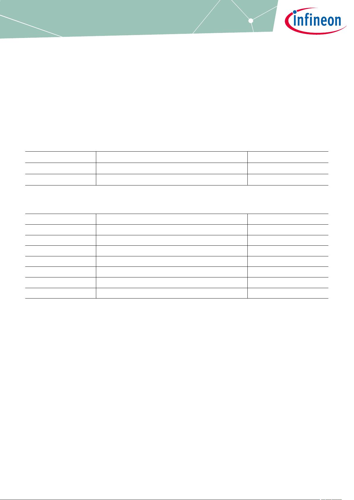
Referenced documents
Table 1 Reference documents
Document type Document reference Issue date
Data Sheet See Table 2
User Manual Infineon-TLE985xQX-UserManual-v01_00-EN.pdf 2019-12-10
Aected products
Table 2 List of aected products
Device Reference datasheet Issue date
TLE9850QX Infineon-TLE9850QX-DataSheet-v01_00-EN.pdf 2019-07-26
TLE9851QXW Infineon-TLE9851QXW-DataSheet-v01_01-EN.pdf 2020-03-23
TLE9852QX Infineon-TLE9852QX-DataSheet-v01_00-EN.pdf 2019-07-26
TLE9853QX Infineon-TLE9853QX-DataSheet-v01_00-EN.pdf 2019-07-26
TLE9854QX Infineon-TLE9854QX-DataSheet-v01_00-EN.pdf 2019-07-26
TLE9854QXW Infineon-TLE9854QXW-DataSheet-v01_01-EN.pdf 2020-03-23
TLE9855QX Infineon-TLE9855QX-DS-DataSheet-v01_00-EN.pdf 2019-07-26
Errata sheet Please read the Important Notice and Warnings at the end of this document 1.0
www.infineon.com 2020-07-24
Page 2

TLE985x-Errata-100-Infineon
TLE985xQX(W) Family
Table of contents
Table of contents
Overview . . . . . . . . . . . . . . . . . . . . . . . . . . . . . . . . . . . . . . . . . . . . . . . . . . . . . . . . . . . . . . . . . . . . . . . . . . . . . . .1
Table of contents . . . . . . . . . . . . . . . . . . . . . . . . . . . . . . . . . . . . . . . . . . . . . . . . . . . . . . . . . . . . . . . . . . . . . . . 2
1 Product errata . . . . . . . . . . . . . . . . . . . . . . . . . . . . . . . . . . . . . . . . . . . . . . . . . . . . . . . . . . . . . . . . . . . . . . . . . .3
1.1 PLL loss of lock (0000052337-4) . . . . . . . . . . . . . . . . . . . . . . . . . . . . . . . . . . . . . . . . . . . . . . . . . . . . . . . . . . . 3
1.1.1 Workaround . . . . . . . . . . . . . . . . . . . . . . . . . . . . . . . . . . . . . . . . . . . . . . . . . . . . . . . . . . . . . . . . . . . . . . . . . . .3
1.1.1.1 Bypass of PLL and fixed system frequency . . . . . . . . . . . . . . . . . . . . . . . . . . . . . . . . . . . . . . . . . . . . . 3
1.1.1.2 Optional: Use of recovery routine . . . . . . . . . . . . . . . . . . . . . . . . . . . . . . . . . . . . . . . . . . . . . . . . . . . . . 5
1.1.2 Design improvement . . . . . . . . . . . . . . . . . . . . . . . . . . . . . . . . . . . . . . . . . . . . . . . . . . . . . . . . . . . . . . . . . . . 7
2 Application hint . . . . . . . . . . . . . . . . . . . . . . . . . . . . . . . . . . . . . . . . . . . . . . . . . . . . . . . . . . . . . . . . . . . . . . . . 8
2.1 ADC1 (HV-Channel) sampling switch activation . . . . . . . . . . . . . . . . . . . . . . . . . . . . . . . . . . . . . . . . . . . . . 8
2.1.1 Workaround . . . . . . . . . . . . . . . . . . . . . . . . . . . . . . . . . . . . . . . . . . . . . . . . . . . . . . . . . . . . . . . . . . . . . . . . . . .8
Revision history . . . . . . . . . . . . . . . . . . . . . . . . . . . . . . . . . . . . . . . . . . . . . . . . . . . . . . . . . . . . . . . . . . . . . . . . 9
Disclaimer . . . . . . . . . . . . . . . . . . . . . . . . . . . . . . . . . . . . . . . . . . . . . . . . . . . . . . . . . . . . . . . . . . . . . . . . . . . . 10
Errata sheet 2 1.0
2020-07-24
Page 3

TLE985x-Errata-100-Infineon
TLE985xQX(W) Family
Product errata
1 Product errata
This chapter lists the errata of the referenced products and documentation.
1.1 PLL loss of lock (0000052337-4)
Behavior
The TLE985x provides a Phase-Locked-Loop (PLL) to generate the system frequency. Under certain conditions it
may happen that the PLL issues a loss of lock. The probability for an erroneous PLL loss of lock to occur
increases with higher temperature and longer operation times.
Eects
In case of a PLL loss of lock, the system frequency will be switched to free running clock divided by K2, this
might have the following eects to the application:
• System timing do not match anymore, e.g. LIN communication might not work properly, PWM period might
be aected.
• WDT1 reset may occur.
• Digital filter times might not match anymore.
1.1.1 Workaround
1.1.1.1 Bypass of PLL and fixed system frequency
As the source of the loss of lock detection is within the lock detection unit, a possible workaround is to bypass
the PLL and use the internal oscillator (marked blue in Figure 1) as system frequency source only. This will lead
to a fixed system frequency of 40 MHz.
Figure 1 Clock generation unit block diagram
Errata sheet 3 1.0
2020-07-24
Page 4

TLE985x-Errata-100-Infineon
TLE985xQX(W) Family
Product errata
The switch to the internal oscillator will be done in the System Control Register 0 by writing the bit field
SYSCLKSEL to 11B:
Figure 2 SCU_SYSCON0
Due to the fact that this register is protected, it is required to open the register password protection. Please use
the following example as reference:
Change system clock source to f_int
001 SCU_OpenPASSWD();
002 SCU->SYSCON0.reg = (uint32)0xC0;
003 SCU_ClosePASSWD();
Errata sheet 4 1.0
2020-07-24
Page 5

TLE985x-Errata-100-Infineon
TLE985xQX(W) Family
Product errata
Excerpt from SCU.h
001 /* Global Macro Definitions */
002 /**\brief PASSWD Phrases, PASSWD Opened */
003 #define PASSWD_Open (0x98U)
004
005 /**\brief PASSWD Phrases, PASSWD Closed */
006 #define PASSWD_Close (0xA8U)
007
008 /* How to open the password protection/*
009 INLINE void SCU_OpenPASSWD(void)
010 {
011 Field_Wrt32all(&SCU->PASSWD.reg, (uint8)PASSWD_Open);
012 }
013
014 /* How to close the password protection*/
015 INLINE void SCU_ClosePASSWD(void)
016 {
017 Field_Wrt32all(&SCU->PASSWD.reg, (uint8)PASSWD_Close);
018 }
Additional note
In case of "Config Wizard" usage, please select f
as 40 MHz as well, otherwise timings (watchdog trigger, GPT,
SYS
CCU6, …) do not match anymore. Ensure disabling the loss of lock NMI (default setting) as the PLL is not used
anymore:
SCU-NMICON.bit.NMIPLL = 0;
Additionally, it is recommended to verify the EMC behavior in your application, especially if a system frequency
change was done.
1.1.1.2 Optional: Use of recovery routine
In the general case of PLL loss of lock, user soware can try to configure the clock system again by executing the
following sequence:
1. If input clock source is from XTAL (fOSC from OSC_HP), ensure the input frequency is above threshold by
checking OSC_CON.OSC2L.
2. The Prescaler Mode has to be selected (PLL_CON.VCOBYP = 1)
3. If desired, (re-)configure the PLL divider settings.
4. Setting the restart lock detection bit PLL_CON.RESLD = 1
5. Waiting until the PLL VCO part becomes locked (PLL_CON.LOCK = 1)
6. When the LOCK is set again, the Prescaler Mode can be deselected (PLL_CON.VCOBYP = 0) and normal
PLL operation is resumed.
7. Clear the PLL loss of lock NMI flag FNMIPLL.
Errata sheet 5 1.0
2020-07-24
Page 6

TLE985x-Errata-100-Infineon
TLE985xQX(W) Family
Product errata
PLL loss of lock recovery routine
001 #include "tle985x.h"
002
003 /**\brief PASSWD Phrases, PASSWD Opened */
004 #define PASSWD_Open (0x98U)
005 /**\brief PASSWD Phrases, PASSWD Closed */
006 #define PASSWD_Close (0xA8U)
007
008 /* procedure to recover PLL as described in TLE985x User
009 Manual, Chapter 7.3.3.8 */
010 void SCU_RecoverPllLossOfLock(void)
011 {
012 /* variable to store/modify PLL_CON register */
013 uint32 pll_con = SCU->PLL_CON.reg;
014
015 /* set VCOBYP bit and UNPROT_VCOBYP bit */
016 pll_con |= (uint32)(1u << 3u);
017 pll_con |= (uint32)(1u << 19u);
018
019 /* Select Prescaler mode to Bypass PLL */
020 SCU->PASSWD.reg = PASSWD_Open;
021 SCU->PLL_CON.reg = pll_con;
022 SCU->PASSWD.reg = PASSWD_Close;
023
024 /* Restart Lock detection */
025 SCU->PLL_CON.bit.RESLD = 1u;
026
027 /* wait until PLL is locked */
028 /* In case PLL doesn't lock a WDT1 reset is performed */
029 while(SCU->PLL_CON.bit.LOCK != 1){}
030
031 pll_con = SCU->PLL_CON.reg;
032
033 /* clear VCOBYP bit and set UNPROT_VCOBYP bit */
034 pll_con &= ~(uint32)(1u << 3u);
035 pll_con |= (uint32)(1u << 19u);
036
037 /* Set PLL Normal mode */
038 SCU->PASSWD.reg = PASSWD_Open;
039 SCU->PLL_CON.reg = pll_con;
040 SCU->PASSWD.reg = PASSWD_Close;
041 }
In case the recovery routine is used, it is strictly recommended to validate the routine within the application use
case.
Errata sheet 6 1.0
2020-07-24
Page 7

TLE985x-Errata-100-Infineon
TLE985xQX(W) Family
Product errata
1.1.2 Design improvement
The next design release will be done by Q2 / 2021.
This release is fully soware compliant to the existing version, so that it is not required to perform a requalification of the improved device.
Errata sheet 7 1.0
2020-07-24
Page 8

TLE985x-Errata-100-Infineon
TLE985xQX(W) Family
Application hint
2 Application hint
2.1 ADC1 (HV-Channel) sampling switch activation
Behavior
Fast transients on an enabled ADC1 HV-Channel could activate the ADC sampling switch, which will lead to a
load of 10 kΩ (+/- 20%) on the causing channel.
In case the corresponding channel will be selected (sequencer, etc.), the additional load will disappear again.
Eects for MONx pin
The activation will increase the input current (> 100 µA @ VS 13.5 V) on the corresponding MONx pin. This
increased current can cause a voltage drop across the external resistor. Depending on the value of the resistor,
the voltage drop can be so high that a wrong low signal on the MONx will be detected.
2.1.1 Workaround
To achieve robustness against ISO 7637-3 pulses, the recommended R-C filter from the Data Sheet is suicient.
To increase the robustness, an additional 10 nF capacitor (C
filter. See Figure 3.
) is recommended. This will lead to a C-R-C
1MONx
Figure 3 Application diagram example with C-R-C filters at MONx
Errata sheet 8 1.0
2020-07-24
Page 9

TLE985x-Errata-100-Infineon
TLE985xQX(W) Family
Revision history
Revision history
Revision Date Changes
1.0 2020-07-24 Initial release
Errata sheet 9 1.0
2020-07-24
Page 10

Trademarks
All referenced product or service names and trademarks are the property of their respective owners.
Edition 2020-07-24
Published by
Infineon Technologies AG
81726 Munich, Germany
©
2020 Infineon Technologies AG
All Rights Reserved.
Do you have a question about any
aspect of this document?
Email: erratum@infineon.com
Document reference
IFX-wje1594363382351
IMPORTANT NOTICE
The information given in this document shall in no
event be regarded as a guarantee of conditions or
characteristics (“Beschaenheitsgarantie”) .
With respect to any examples, hints or any typical values
stated herein and/or any information regarding the
application of the product, Infineon Technologies
hereby disclaims any and all warranties and liabilities of
any kind, including without limitation warranties of
non-infringement of intellectual property rights of any
third party.
In addition, any information given in this document is
subject to customer’s compliance with its obligations
stated in this document and any applicable legal
requirements, norms and standards concerning
customer’s products and any use of the product of
Infineon Technologies in customer’s applications.
The data contained in this document is exclusively
intended for technically trained sta. It is the
responsibility of customer’s technical departments to
evaluate the suitability of the product for the intended
application and the completeness of the product
information given in this document with respect to such
application.
WARNINGS
Due to technical requirements products may contain
dangerous substances. For information on the types
in question please contact your nearest Infineon
Technologies oice.
Except as otherwise explicitly approved by Infineon
Technologies in a written document signed by
authorized representatives of Infineon Technologies,
Infineon Technologies’ products may not be used in
any applications where a failure of the product or
any consequences of the use thereof can reasonably
be expected to result in personal injury.
 Loading...