

Page 1
User Manual Revision 1.0
www.infineon.com 2020-12-08
DC Motor Control HAT with TLE94112ES
Complies with the Raspberry Pi HAT specification
About this document
Scope and purpose
This user manual describes the DC motor control HAT equipped with the TLE94112ES, a twelve-fold halfbridge driver with integrated power stages. This document provides detailed information on the board’s
content, layout and use. It should be used in conjunction with the TLE94112ES datasheet, which contains
full technical details on the device specification and operation.
Intended audience
Engineers, hobbyists and students who want to add a powerful motor control to their projects.
Related information
Table 1 Supplementary links and document references
Reference
Description
TLE94112ES datasheet
Product page which contains reference information for the multiple
half-bridge driver TLE94112ES
TLE941xy SPI interface
Application note for the SPI interface of the multiple half-bridge
driver family TLE941xy
DC motor HAT with TLE94112ES
Information page for DC Motor Control HAT with TLE94112ES
Library for TLE94112ES on GitHub
Software library for TLE94112ES including examples
Page 2

User Manual 2 Revision 1.0
2021-03-
Title
Title_continued
Introduction
Table of Contents
About this document ....................................................................................................................... 1
1 Introduction .................................................................................................................. 3
1.1 DC Motor Control HAT overview ............................................................................................................. 3
1.2 Key features ............................................................................................................................................. 4
1.3 Application diagram for bi-directional DC motor applications ............................................................. 5
2 DC Motor Control HAT description ................................................................................... 6
2.1 Overview .................................................................................................................................................. 6
2.2 Schematics .............................................................................................................................................. 7
2.3 Layout ...................................................................................................................................................... 8
2.4 Bill of Material of the DC Motor Control HAT .......................................................................................... 9
2.5 CS Pin Selection ..................................................................................................................................... 11
2.6 EEPROM ................................................................................................................................................. 12
2.7 Backpowering ........................................................................................................................................ 12
2.8 Stacking multiple DC Motor Control HATs ........................................................................................... 12
2.9 Pin assignment ...................................................................................................................................... 13
2.10 Pin definitions and functions ............................................................................................................... 14
3 TLE94112ES overview ................................................................................................... 15
3.1 Key features of the TLE94112ES ........................................................................................................... 15
3.2 Block diagram ........................................................................................................................................ 16
3.3 Pin assignment ...................................................................................................................................... 17
3.4 Pin definitions and functions ................................................................................................................ 18
4 Getting started ............................................................................................................. 19
5 Revision History ........................................................................................................... 20
Page 3
User Manual 3 Revision 1.0
2021-03-
DC Motor HAT with TLE94112ES
For Raspberry Pi
1 Introduction
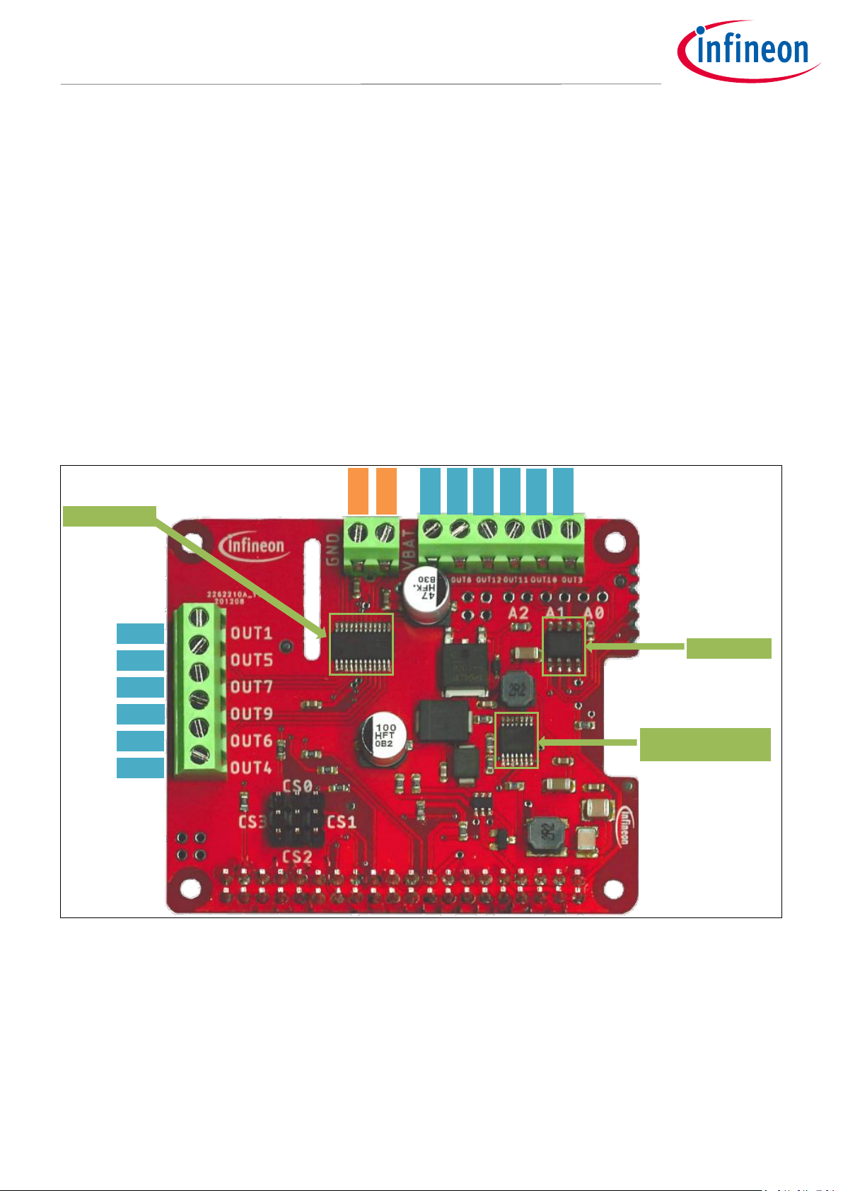
1.1 DC Motor Control HAT overview
The DC Motor Control HAT with TLE94112ES makes it easy to control up to six independent or eleven
cascaded bidirectional DC motors.
The HAT can be controlled by a compatible Raspberry Pi via the SPI interface of the TLE94112ES.
The board features an Infineon TLE94112ES, a twelve-fold half-bridge driver with integrated MOSFETs.
Each half-bridge can drive peak currents up to 0.9 A and DC current in the range of 200 mA to 500 mA,
depending on the application conditions and the number of activated outputs.
The DC Motor Control HAT has an active reverse polarity protection with the p-channel MOSFET
IPD50P04P4L-11.
The HAT can power the Raspberry Pi using Infineon’s OPTIREG™ DC/DC converter TLS4125D0EPV50.
The DC Motor Control HAT can be easily connected to a Raspberry Pi via its 40-pin header.
Figure 1 DC Motor Control HAT with TLE94112ES
TLE94112ES
EEPROM
TLS4125D0EP V50
OUT2
OUT8
OUT12 OUT11
OUT10
OUT3
OUT1
OUT5
OUT7
OUT9
OUT6
OUT4
VBAT
GND
Page 4

User Manual 4 Revision 1.0
2021-03-
DC Motor HAT with TLE94112ES
For Raspberry Pi
1.2 Key features
The DC Motor Control HAT has the following features:
Can be controlled by compatible Raspberry Pis:
o 1 Mod. A+, 1 Mod. B+, 2 Mod. B, 2 Mod. B v1.2, 3 Mod. A+, 3 Mod. B, 3 Mod. B+, 4 Mod. B
o Zero, Zero W
Brushed DC Motor Control up to 0.9 A peak
o 5.5 – 18 V normal operating input voltage
o 18 – 20 V extended operating input voltage
Control of:
o Six independent bidirectional DC motors
o Eleven cascaded bidirectional DC motors
SPI interface for high configurability and detailed diagnosis
Protections:
o Overtemperature
o Overcurrent
o Undervoltage
o Overvoltage
Detailed diagnosis per MOSFET:
o Individual open load detection
o Individual overcurrent detection
Paralleling outputs for higher current capability (up to 3.6 A)
Motor speed control by PWM
o Three independent PWM generators
o PWM frequency: 80 Hz, 100 Hz or 200 Hz
o 8-bit resolution, 0.5% duty cycle steps
o Active freewheeling for lower power dissipation
Multiple HATs can be stacked to control an increased number of motors
Reverse polarity protection with IPD50P04P4L-11
Powering of Raspberry Pi with up to 2.5A with TLS4125D0EPV50
EEPROM containing HAT information
Page 5
User Manual 5 Revision 1.0
2021-03-
DC Motor HAT with TLE94112ES
For Raspberry Pi
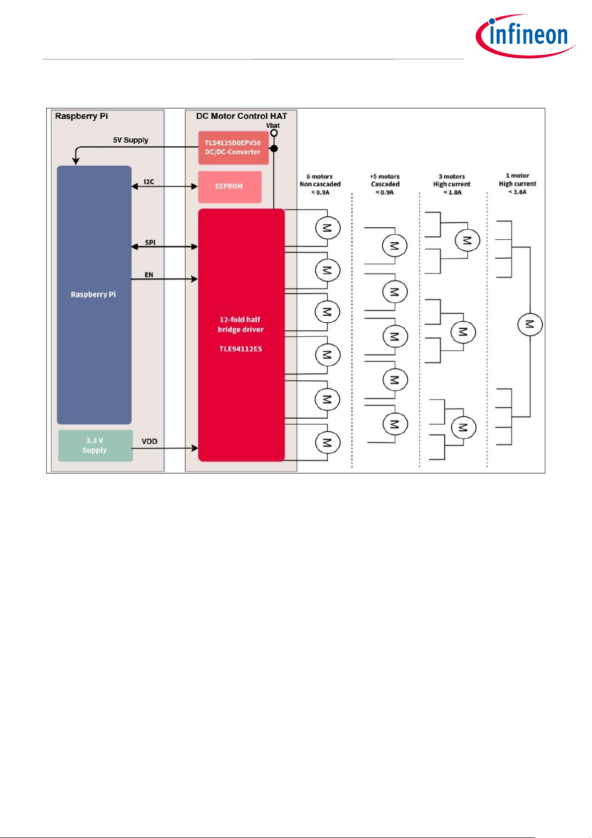
1.3 Application diagram for bi-directional DC motor applications
Figure 2 Simplified application diagram with TLE94112ES driving DC motors
Refer to the TLE94112ES datasheet for more information.
Page 6

User Manual 6 Revision 1.0
2021-03-
DC Motor HAT with TLE94112ES
For Raspberry Pi
2 DC Motor Control HAT description
For a safe and optimized motor control design, some discrete components are needed.
Figure 4, Figure , Figure and Figure 7 show the schematics and the corresponding layout of the DC Motor
Control Shield with TLE94112ES.
2.1 Overview
Figure 3 DC Motor Control HAT connectors
TLE94112ES
The input of the TLE is connected to different capacitors. C11 is there to smooth VCC, the input voltage, C13 to
smooth VDD, the 3.3V supply, so glitches do not influence the functionality of the motor driver. C14 and C12 are
included to stabilize the input voltage.
TLS4125
The DC/DC converter, the TLS4125D0EPV50 is connected to multiple capacitors and inductors on the input and
the output side of the chip. C_IN compensates possible drops in the supply voltage. C56 is there to smooth the
input voltage, so glitches cannot disturb the functionality of the converter. L_IN combined with C52, C53, C54
and C55 create an EMI filter. This filter protects the TLS against electromagnetic interference. At the output of
the chip L_OUT with C58 and C59 are there to support the voltage conversion and C57 is responsible for
stabilizing the output voltage.
OUT2
OUT8
OUT12
OUT11
OUT10
OUT3
OUT1
OUT5
OUT7
OUT9
OUT6
OUT4
VBAT
GND
Page 7
User Manual 7 Revision 1.0
2021-03-
DC Motor HAT with TLE94112ES
For Raspberry Pi
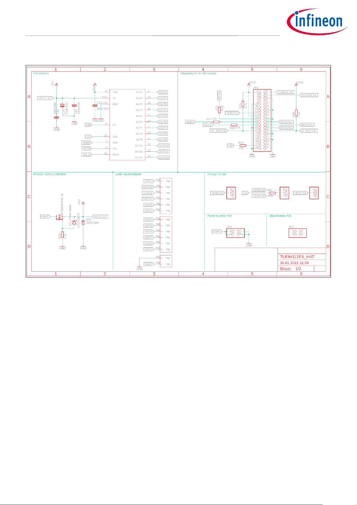
2.2 Schematics
Figure 4 Schematic Motor Control HAT for Raspberry Pi with TLE94112ES (1/2)
Page 8

User Manual 8 Revision 1.0
2021-03-
DC Motor HAT with TLE94112ES
For Raspberry Pi
Figure 5 Schematic DC Motor Control HAT for Raspberry Pi with TLE94112ES (2/2)
2.3 Layout
Figure 6 and Figure 7 show the layout of the DC Motor Control HAT with TLE94112ES.
Figure 6 DC Motor Control HAT – Bottom and top layers
Page 9

User Manual 9 Revision 1.0
2021-03-
DC Motor HAT with TLE94112ES
For Raspberry Pi
Figure 7 DC Motor Control HAT for Raspberry Pi with TLE94112ES – Layout
2.4 Bill of Material of the DC Motor Control HAT
Qty
Value
Device
Package
Parts
Description
3
PINHD-1X3
1X03
U$7, U$17,
U$19
PIN HEADER
1
PINHD-1X5
1X05
JP4
PIN HEADER
2
PINHD-2X2
2X02
JP2, JP8
PIN HEADER
1
PINHD-2X20
2X20
JP1
PIN HEADER
1
SJ
SJ
SJ1
SMD solder
JUMPER
1
100k
R-EU_R0603
R0603
R53
RESISTOR,
European symbol
1
100k/1%
R-EU_R0603
R0603
R5
RESISTOR,
European symbol
3
100n/16V
C-EUC0603
C0603
C1, C13,
C57
CAPACITOR,
European symbol
5
100n/20V
C-EUC0603
C0603
C11, C12,
C53, C55,
C56
CAPACITOR,
European symbol
Page 10

User Manual 10 Revision 1.0
2021-03-
DC Motor HAT with TLE94112ES
For Raspberry Pi
1
100u/20V
CPOL-EUD
PANASONIC_D
CIN1
POLARIZED
CAPACITOR,
European symbol
2
10k
R-EU_R0603
R0603
R3, R52
RESISTOR,
European symbol
1
10u/20V
C-EUC1206
C1206
C54
CAPACITOR,
European symbol
1
12VZENER
12VZENER
SOD323_ST
D21 1
1k6/1%
R-EU_R0603
R0603
R6
RESISTOR,
European symbol
2
22u/16V
C-EUC1210K
C1210K
C58, C59
CAPACITOR,
European symbol
1
2PIN-WTBCONNECTO
R
2PIN-WTB-CONNECTOR
2PIN-WTBCONNECTOR
U$8 4
4.7k
R-EU_R0603
R0603
R2, R25,
R35, R36
RESISTOR,
European symbol
1
4.7u/20V
C-EUC1206
C1206
C52
CAPACITOR,
European symbol
5
470
R-EU_R0603
R0603
R1, R31,
R32, R33,
R34
RESISTOR,
European symbol
1
47k
R-EU_R0603
R0603
R4
RESISTOR,
European symbol
1
47uF/20V
CPOL-EUD
PANASONIC_D
C14
POLARIZED
CAPACITOR,
European symbol
2
6PIN-WTBCONNECTO
R
6PIN-WTB-CONNECTOR
6PIN-WTBCONNECTOR
U$10,
WTB1 1
CAT24C32
CAT24C32
SOIC8
U$2 1
IPD50P04P4
L-11
IPD50P04P4L-11
PG-TO252-3-313
U$6 1
MBRS320T3
G - 20V
PEAK
ON_SEMICONDUCTOR_MBRS3200T3
GON_SEMICONDUCTOR_MBRS3200T
3G_0_0
ON_SEMICONDUC
TOR_MBRS3200T3
G_0
D51
ONSC-D-K1A2-2_A
1
DMG2305U
X
DMG2305UX
SOT23
U$9 1
DMMT5401
DMMT5401
SOT26
U$11 1
SM6T39A
SUPPRESSOR-SMBJ
SMBJ
D22
Suppressor diode
1
TLE94112ES
TLE94112ES
SSOP24
U$1 1
TLS4125D0
EPV50
TLS4125D0EPV50
TSDSO-14
U$3 2
TYS50402R
2N-10
TYS50402R2N-10
5040
U$4, U$5
Figure 8 DC Motor Control HAT with TLE94112ES – Bill of Material (BOM)
Page 11
User Manual 11 Revision 1.0
2021-03-
DC Motor HAT with TLE94112ES
For Raspberry Pi
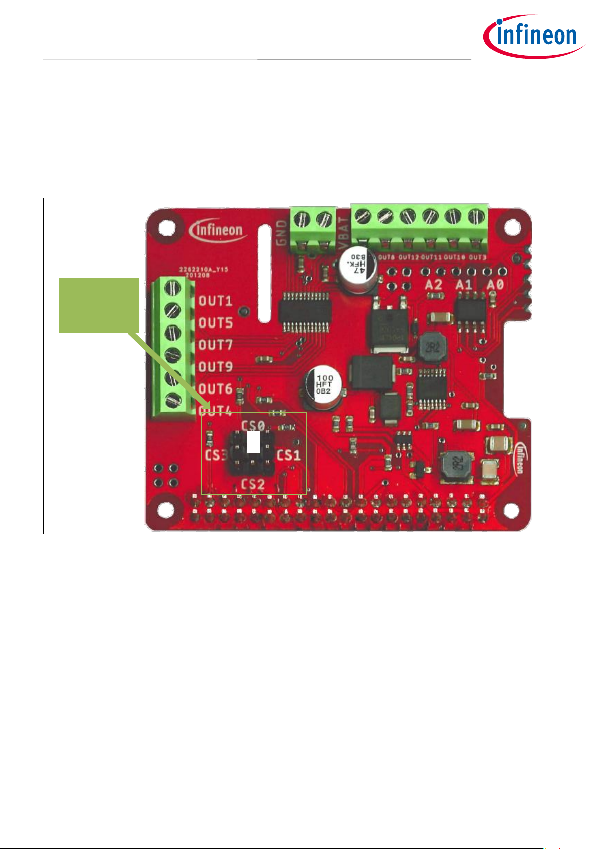
2.5 CS Pin Selection
The GPIO 8 (CS0) of the Raspberry Pi is used by default to control the CS (Chip Select) input of the
TLE94112ES (Figure 9).
Alternatively, GPIO 7 (CS1), GPIO 22 (CS2) or GPIO 25 (CS3) of the Raspberry Pi can be used instead to
stack multiple HATs (refer to section 2.8). In this case, the jumper on the Pinheader can be changed to the
matching CS pin (Figure ).
Figure 9 Control of CSN of TLE94112ES by GPIO 8 (CS0)
GPIO 8
controls CS
input of the
TLE94112ES
Page 12

User Manual 12 Revision 1.0
2021-03-
DC Motor HAT with TLE94112ES
For Raspberry Pi
Figure 10 Control of CS of TLE94112ES by GPIO 7 (CS1)
2.6 EEPROM
The DC Motor Control HAT also contains an Electrically Erasable Programmable Read-Only Memory
(EEPROM). It allows the Raspberry Pi firmware to automatically load the necessary drivers for the HAT.
The CAT24C32 communicates via I2C on ID_SD (GPIO 27) and ID_SC (GPIO 28) with the Raspberry Pi.
If another HAT with an EEPROM is used concurrently with the DC Motor Control HAT, the address of the
EEPROM can be adjusted by closing the solder bridge marked with A+1. If the pin is left open, the I2C
address is 0x50 and if the bridge is closed it is 0x51.
2.7 Back-Powering
This HAT is able to supply the Raspberry Pi (up to 12.5 W) via its input voltage. The input voltage
(recommended 12V) is converted to 5V and maximum 2.5A by the DC/DC converter TLS4125D0EPV50 from
Infineon. The output of the chip is connected to the 5V pins of the Raspberry Pi. Consequently the power
supply unit of the Raspberry Pi is not necessarily needed. In case the Raspberry Pi is powered separately,
the TLS is protected against voltage collision by a p-channel MOSFET and a transistor array.
2.8 Stacking multiple DC Motor Control HATs
It is possible to stack multiple DC Motor Control HATs to increase the number of controlled motors.
In this configuration, the CS input of each TLE94112ES must be controlled individually by different
microcontroller GPIOs:
- The TLE94112ES of one DC Motor Control HAT is controlled by GPIO 8 (default setting, Figure ).
GPIO 7
controls CS
input of the
TLE94112ES
Page 13

User Manual 13 Revision 1.0
2021-03-
DC Motor HAT with TLE94112ES
For Raspberry Pi
- The TLE94112ES of the other DC Motor Control HAT is controlled by GPIO 7 (Figure ).
The combination with different HATs is possible in general, but compatibility depends on pin usage and
bus addresses and cannot be guaranteed for every HAT.
2.9 Pin assignment
To use the DC Motor Control HAT, the necessary control signals can be applied directly at the Raspberry
Pi connectors.
Figure shows the pinout/connectors of the DC Motor Control HAT with TLE94112ES.
Figure 13 Connectors of DC Motor Control HAT
Page 14

User Manual 14 Revision 1.0
2021-03-
DC Motor Shield with TLE94112EL
For Raspberry Pi
2.10 Pin definitions and functions
Pin
I/O 1
Function
GND
-
GND
Common 0V reference for all components on the DC Motor Control HAT.
VBAT
-
Battery supply (5.5 – 18V normal, 18-20V extended)
Connected to the battery voltage of the HAT
VDD - Logic supply (3.3V from Raspberry Pi)
VCC - Supply for Backpowering (5V for Raspberry)
SCLK
I
Serial Clock Input 2
MOSI
I
Master Output Slave Input 2
MISO
O
Master Input Slave Output 2
CS0 I Chip Select 0
2, Error! Bookmark not defined.
CS1 I Chip Select 1
2, Error! Bookmark not defined.
CS2 I Chip Select 2
2, Error! Bookmark not defined.
CS3
I
Chip Select 3
2, Error! Bookmark not defined.
EN
I
Enable Input
Connected to GPIO 26 of the Raspberry Pi. When set to low device goes in sleep
mode with low current consumption.
OUT1-12
O
Connectors for outputs of the half-bridges 1-12
ID_SD
I
Connected to the EEPROM
ID_SC
I
Connected to the EEPROM
1
With respect to the TLE94112ES
2
Connected to the SPI interface of the Raspberry Pi
3
Refer to chapter 2.5
Page 15
User Manual 15 Revision 1.0
2021-03-
DC Motor Shield with TLE94112EL
For Raspberry Pi
3 TLE94112ES overview
The TLE94112ES is a protected twelve-fold half-bridge driver designed especially for automotive motion
control applications such as heating, ventilation and air conditioning (HVAC) flap DC motor control. It is part of
a larger family offering half-bridge drivers from three outputs to twelve outputs with direct interface or SPI
interface.
The half bridge drivers are designed to drive DC motor loads in sequential or parallel operation. Operation
modes forward, reverse, brake and high impedance are controlled from a 16-bit SPI interface. It offers diagnosis
features such as short circuit, open load, power supply failure and overtemperature detection.
In combination with its low quiescent current, this device is attractive among others for automotive
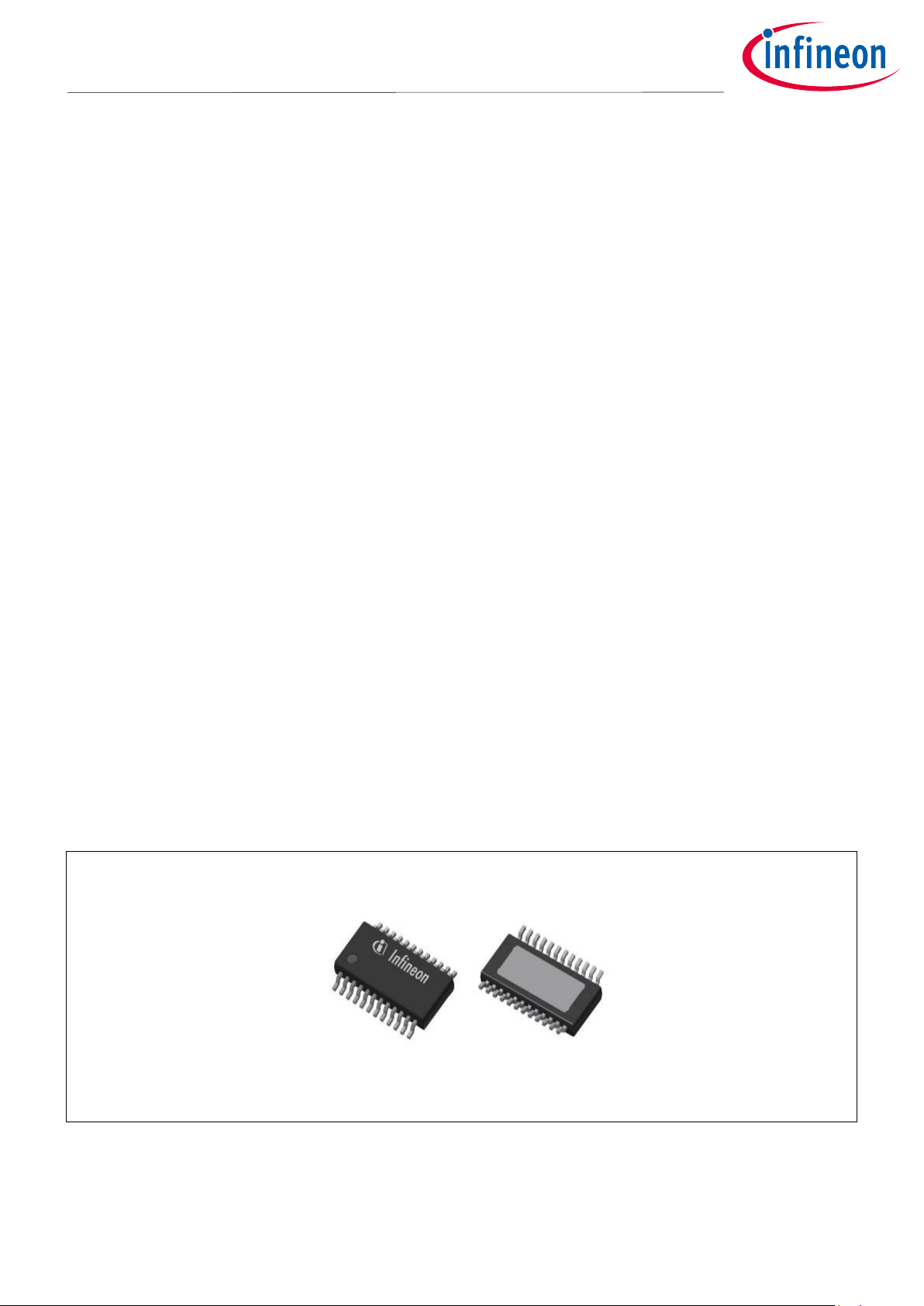
applications. The small fine pitch exposed pad package, PG-TSDSO-24, provides a good thermal performance
and reduces PCB-board space and costs.
3.1 Key features of the TLE94112ES
Twelve half-bridge power outputs
Optimized EMC behavior
Very low power consumption in sleep mode
3.3V / 5V compatible inputs with hysteresis
All outputs with overload and short circuit protection
Independently diagnosable outputs (overcurrent, open load)
Open load diagnostics in ON-state for all high-side and low-side
Outputs with selectable open load thresholds (HS1, HS2)
16-bit Standard SPI interface with daisy chain and in-frame response capability for control and diagnosis
Fast diagnosis with the global error flag
PWM capable outputs for frequencies 80Hz, 100Hz and 200Hz with 8-bit duty cycle resolution
Overtemperature pre-warning and protection
Over- and Undervoltage lockout
Cross-current protection
AEC-100 Qualified
Figure 14 PG-TSDSO-24 Package
Page 16

User Manual 16 Revision 1.0
2021-03-
DC Motor Shield with TLE94112EL
For Raspberry Pi
3.2 Block diagram
Figure 15 Block diagram TLE94112ES
SCLK
EN
CSN
SDI
SDO
BIAS &
MONITOR
UNDERVOLTAGE &
OVERVOLTAGE
MONITOR
VDD
ERROR
DETECTION
VS1
CHARGE
PUMP
open load
detection
current
control
high-side
driver
low-side
driver
short to
battery
detection
temp
sensor
current
control
short to
battery
detection
high-side
driver
low-side
driver
short to
battery
detection
temp
sensor
open load
detection
current
control
short to
battery
detection
high-side
driver
low-side
driver
short to
battery
detection
temp
sensor
open load
detection
current
control
short to
battery
detection
high-side
driver
low-side
driver
short to
battery
detection
temp
sensor
current
control
short to
battery
detection
OUT 7
OUT 5
OUT 3
OUT 1
open load
detection
current
control
short to
battery
detection
low-side
driver
short to
battery
detection
temp
sensor
open load
detection
current
control
short to
battery
detection
high-side
driver
low-side
driver
short to
battery
detection
temp
sensor
current
control
short to
battery
detection
high-side
driver
low-side
driver
short to
battery
detection
temp
sensor
current
control
short to
battery
detection
high-side
driver
low-side
driver
short to
battery
detection
temp
sensor
current
control
short to
battery
detection
temp
sensor
High-side
driver
Low-side
driver
Power driver
Temp.
sensor
Power stage
LOGIC CONTROL
& LATCH
SPI INTERFACE
12-Fold Half Bridge Driver
SPI Interface
Open load
detection
Overload
detection
Overtemp.
detection
Open load
detection
Overload
detection
Overtemp.
detection
PWM
GENERATOR
GND
GND
OUT 2
OUT 4
OUT 6
OUT 12
OUT 10
OUT 8
OUT 9
OUT 11
GND GND
VS2
Page 17

User Manual 17 Revision 1.0
2021-03-
DC Motor Shield with TLE94112EL
For Raspberry Pi
3.3 Pin assignment
Figure 16 Pin assignment TLE94112ES (top view)
GND
OUT 2
OUT 8
VS2
SCLK
CSN
OUT 12
SDO
EN
OUT 9
OUT 6
OUT 4
GND
GND
OUT 1
OUT 5
OUT 7
SDI
VDD
OUT 11
VS1
OUT 10
OUT 3
GND
18
17
16
15
14
13
24
23
22
21
20
19
1
2
3
4
5
6
7
8
9
10
11
12
Page 18

User Manual 18 Revision 1.0
2021-03-
DC Motor Shield with TLE94112EL
For Raspberry Pi
3.4 Pin definitions and functions
Pin
Symbol
Function
1
GND
Ground. All ground pins should be externally connected together.
2
OUT 1
Power half-bridge 1
3
OUT 5
Power half-bridge 5
4
OUT 7
Power half-bridge 7
5
SDI
Serial data input with internal pull down
6
VDD
Logic supply voltage
7
SDO
Serial data output
8
EN
Enable with internal pull-down; Places device in standby mode by pulling the
EN line Low
9
OUT 9
Power half-bridge 9
10
OUT 6
Power half-bridge 6
11
OUT 4
Power half-bridge 4
12
GND
Ground. All ground pins should be externally connected together.
13
GND
Ground. All ground pins should be externally connected together.
14
OUT 3
Power half-bridge 3
15
OUT 10
Power half-bridge 10
16
VS1
Main supply voltage for power half bridges. VS1 should be externally connected to
VS2.
17
OUT11
Power half-bridge 11
18
OUT12
Power half-bridge 12
19
CSN
Chip select Not input with internal pull up
20
SCLK
Serial clock input with internal pull down
21
VS2
Main supply voltage for power half bridges. VS1 should be externally connected to
VS1.
22
OUT 8
Power half-bridge 8
23
OUT 2
Power half-bridge 2
24
GND
Ground. All ground pins should be externally connected together.
EDP
-
Exposed Die Pad; For cooling purpose only - not usable as electrical ground.
Electrical ground must be provided by pins 1, 12, 13, 24
Page 19

User Manual 19 Revision 1.0
2021-03-
DC Motor Shield with TLE94112EL
For Raspberry Pi
4 Getting started
For a quick and easy set up check out the Quick Start Guide available on the website and on
github.com/Infineon/multi-half-bridge.
Page 20

User Manual 20 Revision 1.0
2021-03-
DC Motor Shield with TLE94112EL
For Raspberry Pi
5 Revision History
Major changes since the last revision
Page or Reference
Description of change
V1.0, 2021-03-10
First release
Page 21

Published by
Infineon Technologies AG
81726 Munich, Germany
© 2021 Infineon Technologies AG.
All Rights Reserved.
Do you have a question about this
document?
Email: erratum@infineon.com
Document reference
IMPORTANT NOTICE
The information contained in this application note is
given as a hint for the implementation of the product
only and shall in no event be regarded as a
description or warranty of a certain functionality,
condition or quality of the product. Before
implementation of the product, the recipient of this
application note must verify any function and other
technical information given herein in the real
application. Infineon Technologies hereby disclaims
any and all warranties and liabilities of any kind
(including without limitation warranties of noninfringement of intellectual property rights of any
third party) with respect to any and all information
given in this application note.
The data contained in this document is exclusively
intended for technically trained staff. It is the
responsibility of customer’s technical departments
to evaluate the suitability of the product for the
intended application and the completeness of the
product information given in this document with
respect to such application.
For further information on the product, technology,
delivery terms and conditions and prices please
contact your nearest Infineon Technologies office
(www.infineon.com).
WARNINGS
Due to technical requirements products may contain
dangerous substances. For information on the types
in question please contact your nearest Infineon
Technologies office.
Except as otherwise explicitly approved by Infineon
Technologies in a written document signed by
authorized representatives of Infineon
Technologies, Infineon Technologies’ products may
not be used in any applications where a failure of the
product or any consequences of the use thereof can
reasonably be expected to result in personal injury.
Trademarks of Infineon Technologies AG
AURIX™, C166™, CanPAK™, CIPOS™, CoolGaN™, CoolMOS™, CoolSET™, CoolSiC™, CORECONTROL™, CROSSAVE™, DAVE™, DI-POL™, DrBlade™, EasyPIM™,
EconoBRIDGE™, EconoDUAL™, EconoPACK™, EconoPIM™, EiceDRIVER™, eupec™, FCOS™, HITFET™, HybridPACK™, Infineon™, ISOFACE™, IsoPACK™,
i-Wafer™, MIPAQ™, ModSTACK™, my-d™, NovalithIC™, OmniTune™, OPTIGA™, OptiMOS™, ORIGA™, POWERCODE™, PRIMARION™, PrimePACK™,
PrimeSTACK™, PROFET™, PRO-SIL™, RASIC™, REAL3™, ReverSave™, SatRIC™, SIEGET™, SIPMOS™, SmartLEWIS™, SOLID FLASH™, SPOC™, TEMPFET™,
thinQ!™, TRENCHSTOP™, TriCore™.
Trademarks updated August 2015
Other Trademarks
All referenced product or service names and trademarks are the property of their respective owners.
Edition 2017-02-13
AppNote Number
 Loading...