

Page 1
TLE92104 APPKIT
About this document
Scope and purpose
This user manual is intended to help users using the TLE92104 APPKIT. This APPKIT is designed to evaluate
hardware and software functionalities of the TLE92104.
This manual provides additional information about the board's layout, jumper settings, interface and how to
use the GUI.
Intended audience
This document is for everyone who works with the TLE92104 APPKIT.
User Manual Please read the Important Notice and Warnings at the end of this document v1.0
www.infineon.com 2020-12-28
Page 2

TLE92104 APPKIT
Abbreviations
Abbreviations
CSN Chip select
CSIx Current Sense Input x
CSOx Current Sense Output
DC Direct Current or Duty Cycle
EN TLE92104 enable pin
GH1-4 Gate high-side MOSFET for half-bridge 1-4
GL1-4 Gate low-side MOSFET for half-bridge 1-4
GND Ground
GUI Graphic User Interface
MOSFET Metal-Oxide-Semiconductor Field-Effect Transistor
N.C. Not connected
OC Overcurrent
OV Overvoltage
PWM1-3 Pulse Width Modulation channel 1-3
SCLK Serial Clock
SDI Serial Data In
SDO Serial Data Out
SPI Serial Periphery Interface
TJ Junction temperature
UV Undervoltage
VBAT Battery supply voltage
VCP Charge pump voltage
VDD Logic supply voltage
VDH Voltage drain of high-side MOSFET
VS Battery supply voltage
VSP Half-bridge supply voltage
User Manual 2 v1.0
2020-12-28
Page 3

TLE92104 APPKIT
Table of contents
Table of contents
About this document . . . . . . . . . . . . . . . . . . . . . . . . . . . . . . . . . . . . . . . . . . . . . . . . . . . . . . . . . . . . . . . . . . . 1
Abbreviations . . . . . . . . . . . . . . . . . . . . . . . . . . . . . . . . . . . . . . . . . . . . . . . . . . . . . . . . . . . . . . . . . . . . . . . . . . 2
Table of contents . . . . . . . . . . . . . . . . . . . . . . . . . . . . . . . . . . . . . . . . . . . . . . . . . . . . . . . . . . . . . . . . . . . . . . . 3
1 Concept . . . . . . . . . . . . . . . . . . . . . . . . . . . . . . . . . . . . . . . . . . . . . . . . . . . . . . . . . . . . . . . . . . . . . . . . . . . . . . . . 4
2 PCB layout . . . . . . . . . . . . . . . . . . . . . . . . . . . . . . . . . . . . . . . . . . . . . . . . . . . . . . . . . . . . . . . . . . . . . . . . . . . . . 5
3 Connections . . . . . . . . . . . . . . . . . . . . . . . . . . . . . . . . . . . . . . . . . . . . . . . . . . . . . . . . . . . . . . . . . . . . . . . . . . . .6
4 Current Sense Output (CSO) jumper setting . . . . . . . . . . . . . . . . . . . . . . . . . . . . . . . . . . . . . . . . . . . . . . 8
5 SMD test points . . . . . . . . . . . . . . . . . . . . . . . . . . . . . . . . . . . . . . . . . . . . . . . . . . . . . . . . . . . . . . . . . . . . . . . . .9
6 Bill of material . . . . . . . . . . . . . . . . . . . . . . . . . . . . . . . . . . . . . . . . . . . . . . . . . . . . . . . . . . . . . . . . . . . . . . . . 10
7 TLE92104-232 pinout . . . . . . . . . . . . . . . . . . . . . . . . . . . . . . . . . . . . . . . . . . . . . . . . . . . . . . . . . . . . . . . . . . 11
8 APPKIT setup . . . . . . . . . . . . . . . . . . . . . . . . . . . . . . . . . . . . . . . . . . . . . . . . . . . . . . . . . . . . . . . . . . . . . . . . . .12
8.1 Installing the GUI . . . . . . . . . . . . . . . . . . . . . . . . . . . . . . . . . . . . . . . . . . . . . . . . . . . . . . . . . . . . . . . . . . . . . . . 12
8.2 Establishing communication . . . . . . . . . . . . . . . . . . . . . . . . . . . . . . . . . . . . . . . . . . . . . . . . . . . . . . . . . . . . 12
8.3 Using the GUI . . . . . . . . . . . . . . . . . . . . . . . . . . . . . . . . . . . . . . . . . . . . . . . . . . . . . . . . . . . . . . . . . . . . . . . . . . 13
9 How to use the GUI (examples) . . . . . . . . . . . . . . . . . . . . . . . . . . . . . . . . . . . . . . . . . . . . . . . . . . . . . . . . . 15
9.1 Example - PWM DC motor control using half-bridge 1 and 2 . . . . . . . . . . . . . . . . . . . . . . . . . . . . . . . . . 15
9.2 Example - Enabling Adaptive MOSFET Control . . . . . . . . . . . . . . . . . . . . . . . . . . . . . . . . . . . . . . . . . . . . . 17
9.3 Example - Setting blanking, cross-current protection and drain-source monitoring . . . . . . . . . . . .18
9.4 Example - Off-state diagnostics on half-bridge 1 and 2 . . . . . . . . . . . . . . . . . . . . . . . . . . . . . . . . . . . . . .19
10 Schematics and layout . . . . . . . . . . . . . . . . . . . . . . . . . . . . . . . . . . . . . . . . . . . . . . . . . . . . . . . . . . . . . . . . .20
10.1 Schematics . . . . . . . . . . . . . . . . . . . . . . . . . . . . . . . . . . . . . . . . . . . . . . . . . . . . . . . . . . . . . . . . . . . . . . . . . . . . 20
10.2
Layout . . . . . . . . . . . . . . . . . . . . . . . . . . . . . . . . . . . . . . . . . . . . . . . . . . . . . . . . . . . . . . . . . . . . . . . . . . . . . . . . 26
11 Revision history . . . . . . . . . . . . . . . . . . . . . . . . . . . . . . . . . . . . . . . . . . . . . . . . . . . . . . . . . . . . . . . . . . . . . . . 28
Disclaimer . . . . . . . . . . . . . . . . . . . . . . . . . . . . . . . . . . . . . . . . . . . . . . . . . . . . . . . . . . . . . . . . . . . . . . . . . . . . 29
User Manual 3 v1.0
2020-12-28
Page 4
TLE92104 APPKIT
1 Concept
1
Concept
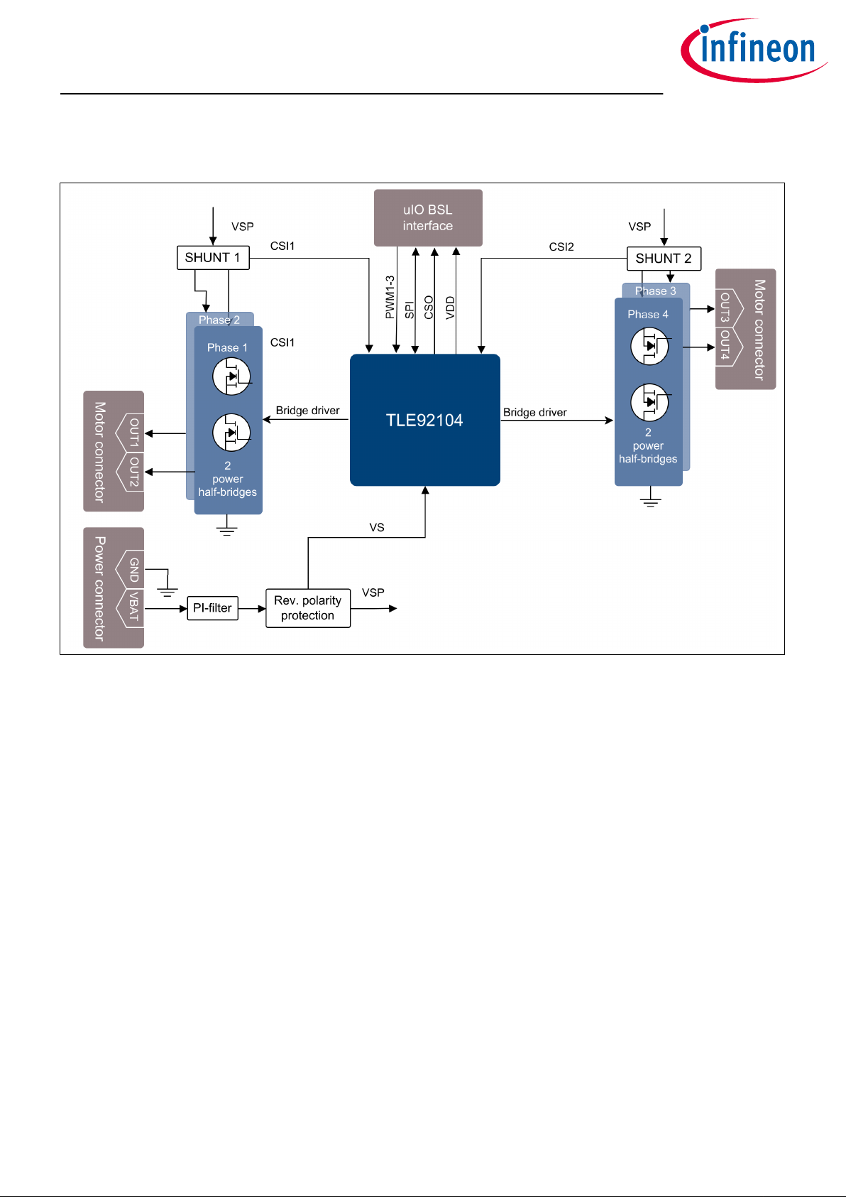
Figure 1 Block diagram
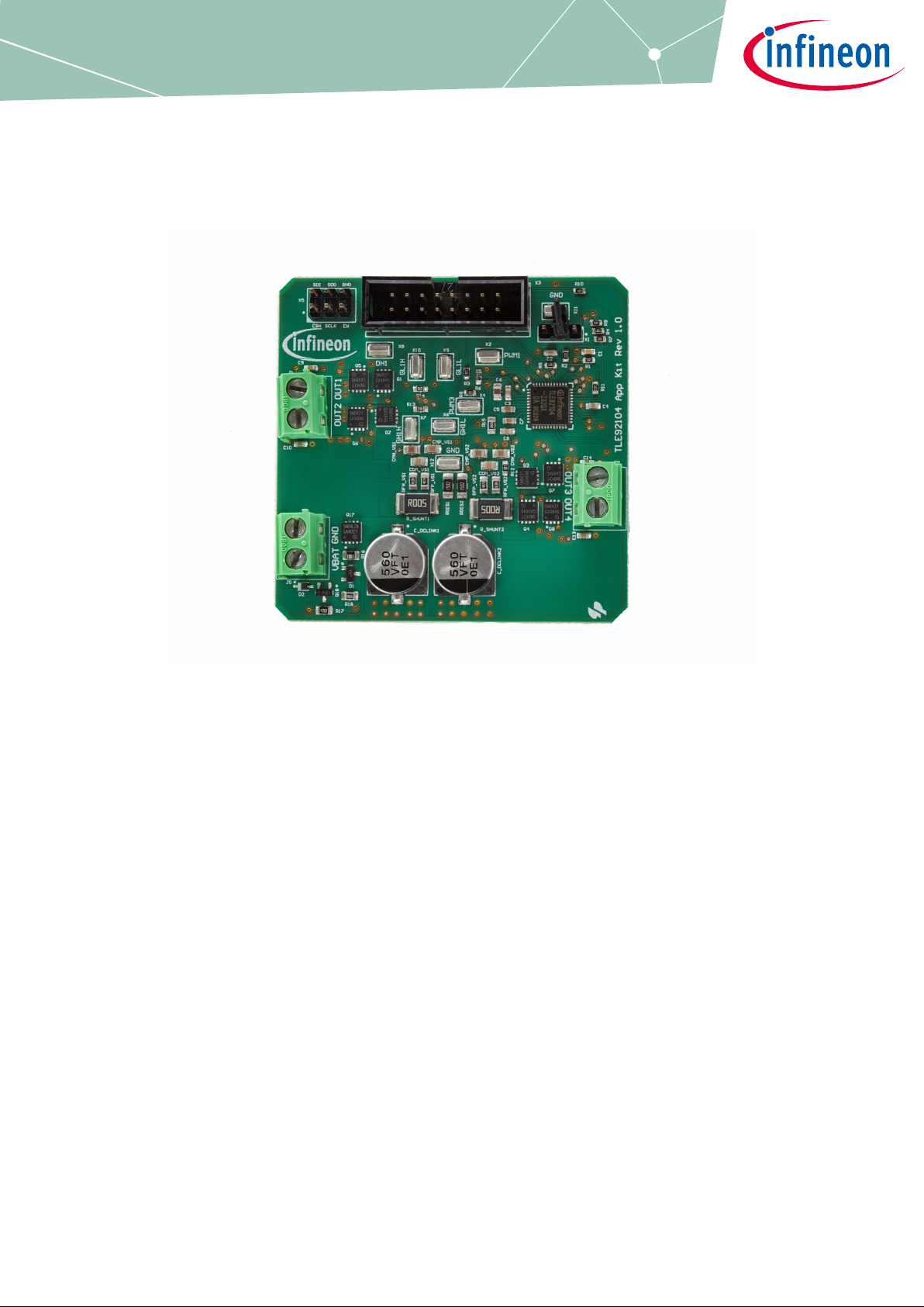
The TLE92104 APPKIT board provides a simple, easy-to-use tool to get familiar with Infineon's Multi MOSFET
Driver TLE92104-232QX (TLE92104).
It contains the TLE92104 and a typical application circuit including 4 MOSFET half-bridges to drive up to
4 DC motors. The board is ready to be connected to a vehicle level power supply and is controlled over SPI.
All pins relevant to control the device can be accessed via the dedicated 8 × 2 header using the uIO-stick by
hitex EMBEDDED TOOLS & SOLUTIONS (http://www.hitex.com/uIO).
The board is powered by the power connector and provides an active on-board reverse-polarity protection for
fastest response time in case of reverse polarity with minimal power-loss during normal operation.
The board allows control of Phase 1-4 which can be used to control up to 4 motors independently that can be
connected to OUT1-4 with the 2 screw terminal block motor connectors.
2 high-side shunts provide load current measurement and monitoring.
User Manual 4 v1.0
2020-12-28
Page 5
TLE92104 APPKIT
2 PCB layout
2
PCB layout
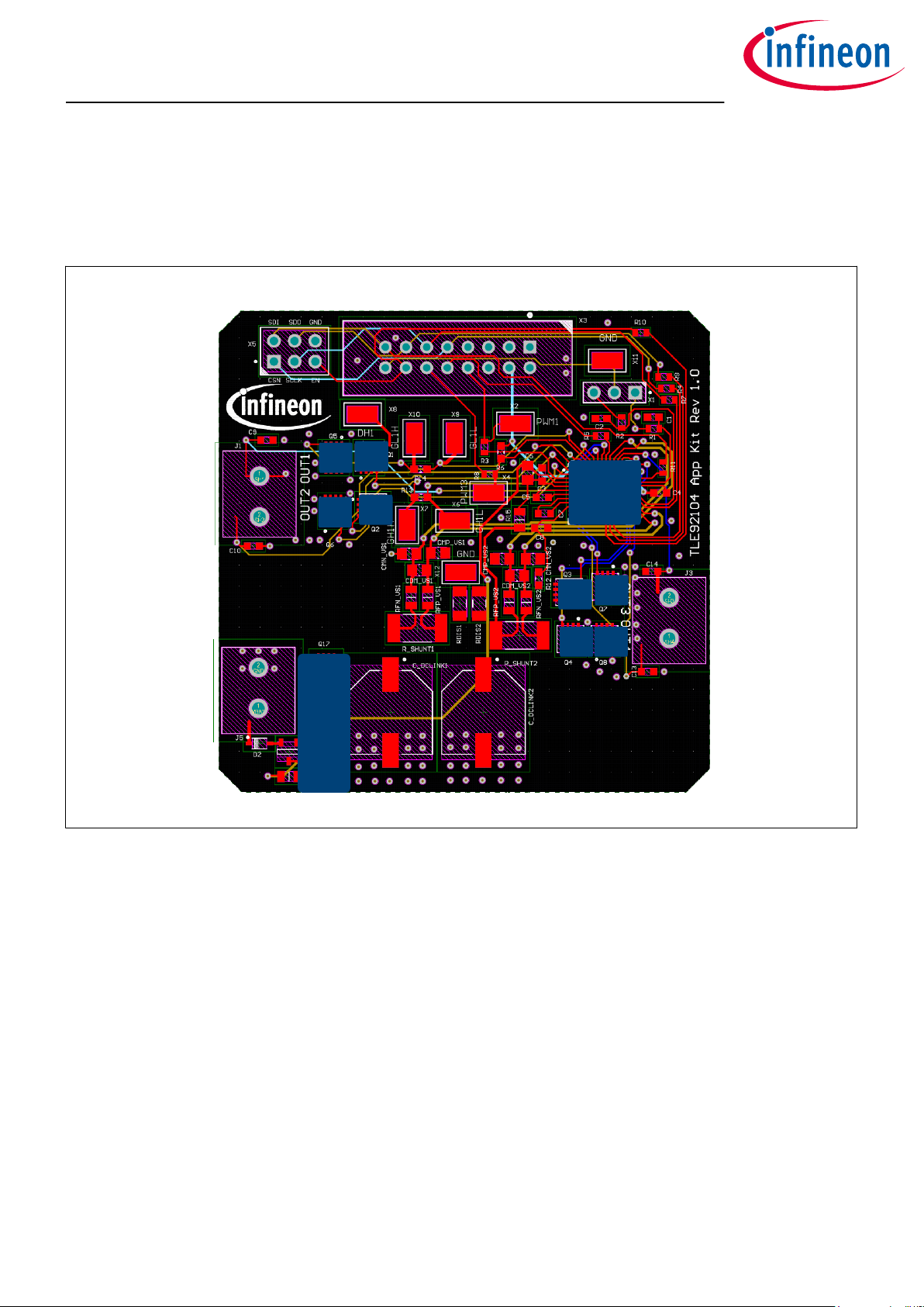
Infineon's TLE92104 is a Multi-MOSFET driver IC providing control of up to 8 n-channel MOSFETs. It supports up
to 4 half-bridges for DC motor control applications such as automotive power seat control or other multi-motor
applications (Datasheet of TLE92104-232QX).
LS1
HS1
TLE92104
LS2
HS2
HS3
LS3
HS4 LS4
Figure 2 PCB layout
HS1-4, LS1-4
Infineon's new OptiMOS™ 5 40 V product family in S3O8 package combines leading power MOSFET technology
with 3.3 × 3.3 mm2 leadless power package for very compact and robust automotive system solutions
(Datasheet of IPZ40N04S5-3R1).
Reverse polarity protection
The active reverse polarity protection is based on the design documented in the "Reverse Polarity Protection
for Embedded Power ICs" Application Note (Z864338247).
User Manual 5 v1.0
2020-12-28
protection
Reverse polarity
Page 6
TLE92104 APPKIT
3 Connections
3
Connections
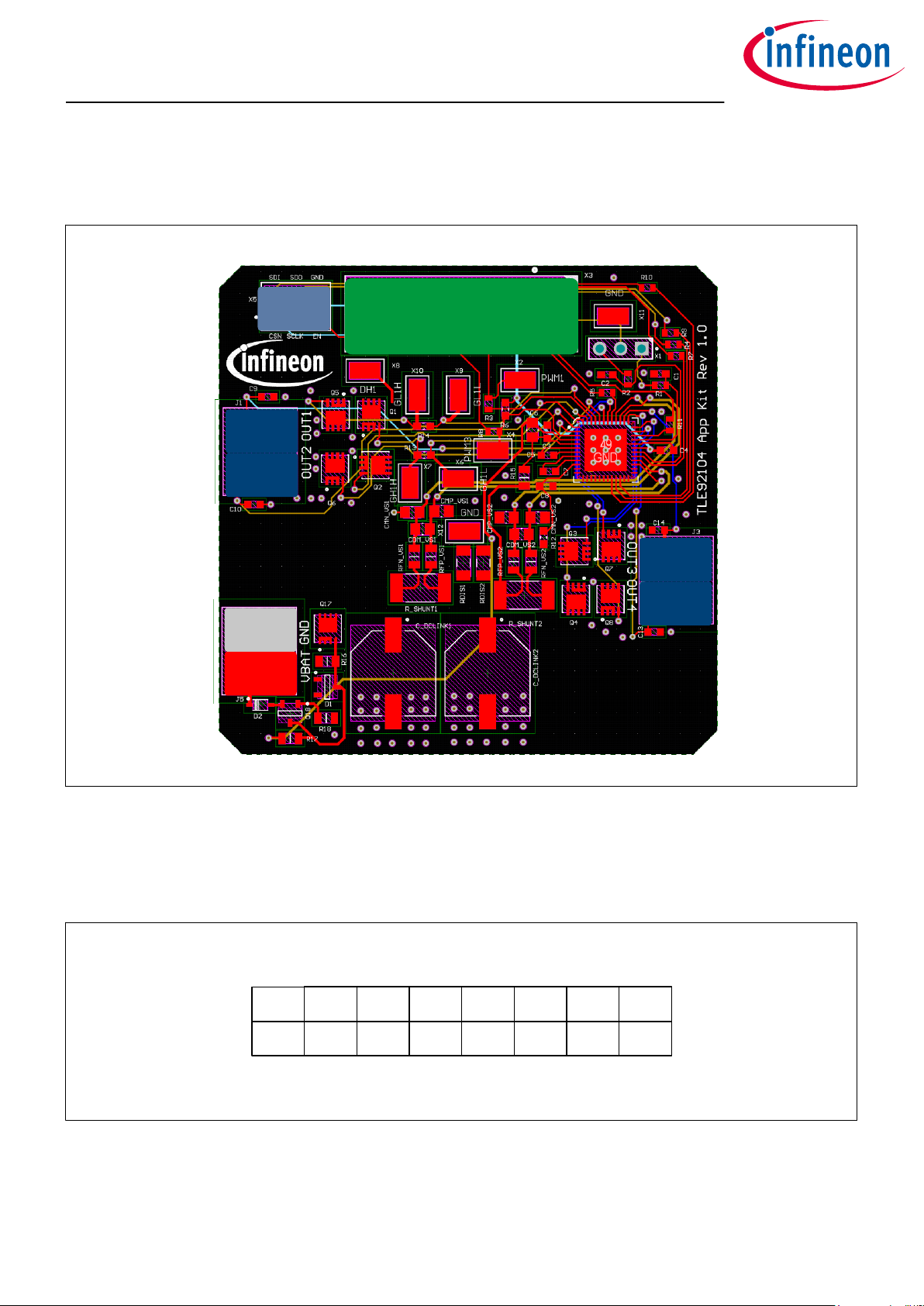
Several external connections are available on the TLE92104 APPKIT.
SPI
header
uIO-stick
interface
OUT 1
OUT 2
OUT 3
OUT 4
Ground
VBAT
Figure 3 Connections
uIO-stick interface
The uIO-stick interface can be used to establish communication with the TLE92104 for programming of the SFRs
and motor control. Setting up the interface can be found in APPKIT setup. The pinout is shown in Figure 4.
SDI SDO SCLK CSN N.C. N.C. N.C. NC.
15 13 11 9 7 5 3 1
16 14 12 10 8 6 4 2
CSOx EN PWM3 PWM2 PWM1 N.C. VDD GND
Figure 4 Pin configuration of uIO-stick
User Manual 6 v1.0
2020-12-28
Page 7
TLE92104 APPKIT
3 Connections
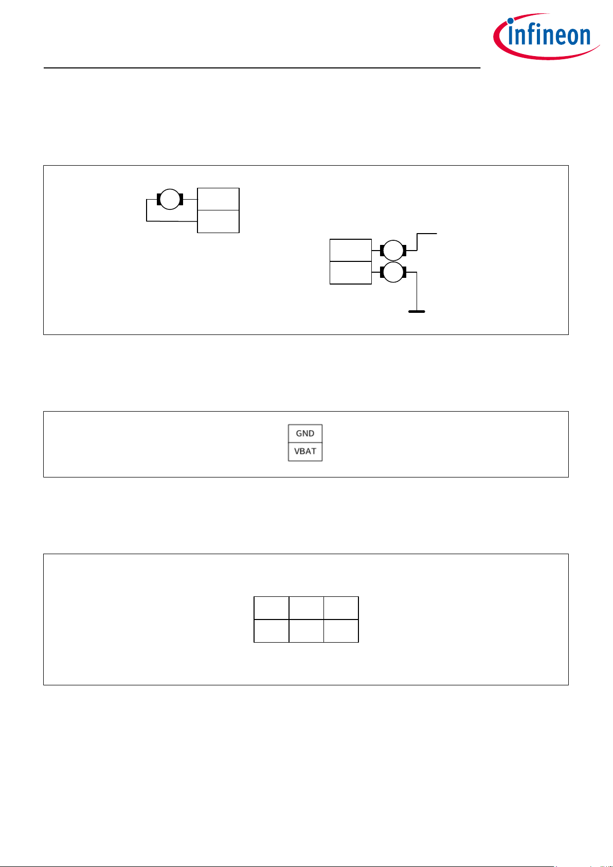
Motor connectors
The screw terminal blocks can be used to connect DC motors in multiple topologies, some examples are shown
in Figure 5.
M
Out 1
Out 2
Out 3
M
VS
Out 4
M
Figure 5 Motor connectors and topologies
Power connector
The screw terminal blocks are used to connect the supply voltage to VBAT and ground to GND.
Figure 6 Power connector
SPI header
The 3 × 2 header can be used for SPI debugging. The pinout is shown in Figure 7.
SDI SDO GND
2 4 6
1 3 5
CSN SCLK EN
Figure 7 SPI header pinout
User Manual 7 v1.0
2020-12-28
Page 8
TLE92104 APPKIT
4 Current Sense Output (CSO) jumper setting
4
Current Sense Output (CSO) jumper setting
The Current Sense Output jumper selects which IC current sense output is connected to the uIO interface. The
signal is routed to the uIO-stick interface pin 16. The pinout is shown in Figure 9.
CSO selection jumper
Figure 8 Current Sense Output selection jumper
CSO2 CSOx CSO1
Figure 9 CSO selection jumper pinout
User Manual 8 v1.0
2020-12-28
Page 9
TLE92104 APPKIT
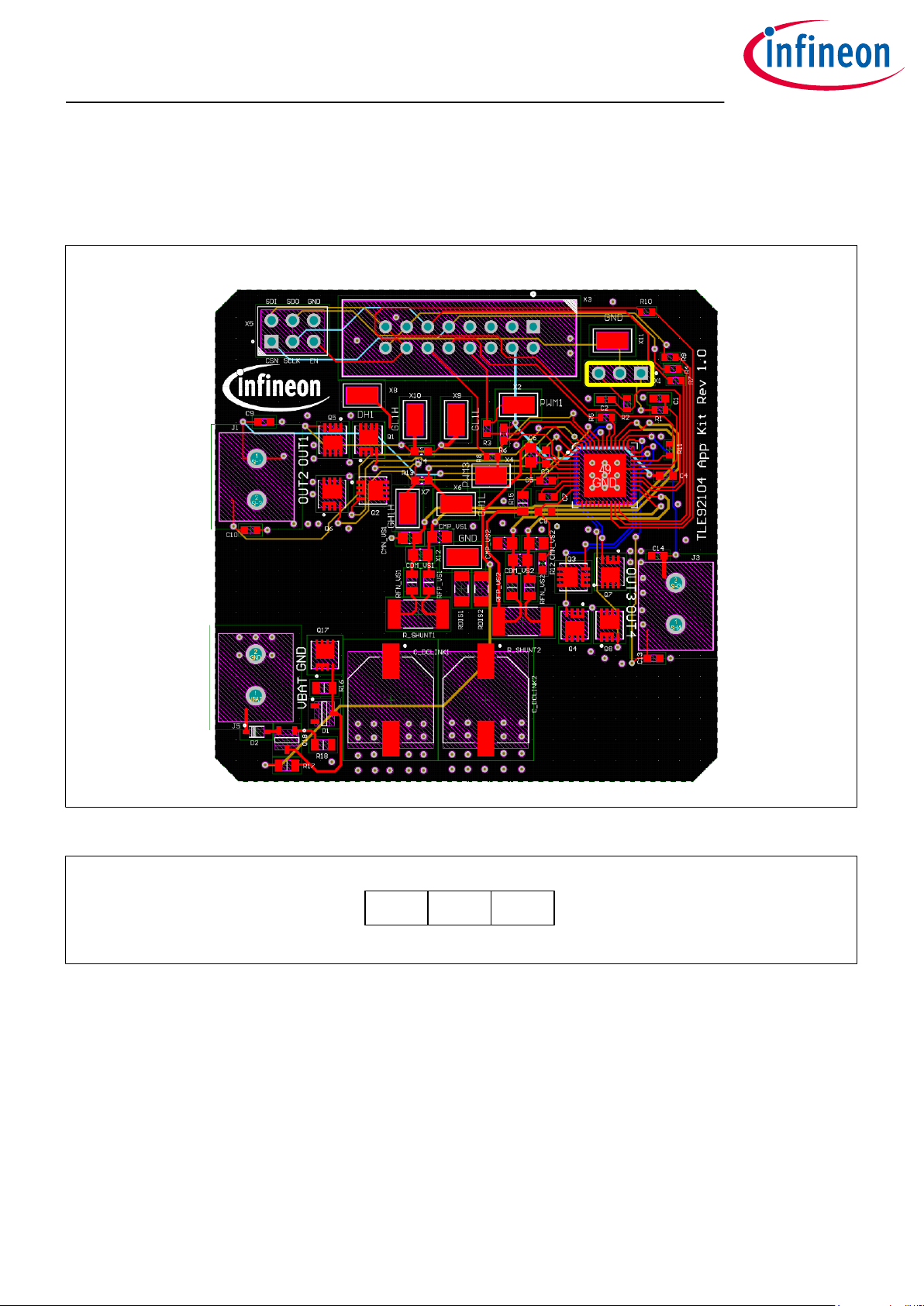
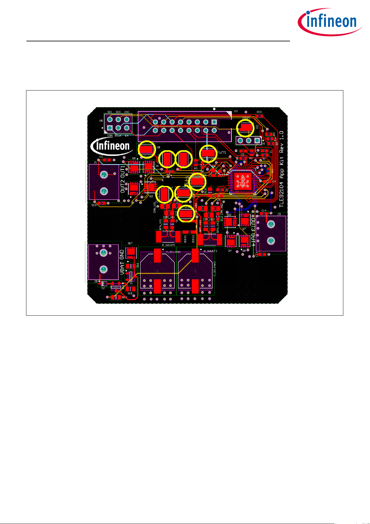
5 SMD test points
5
SMD test points
The TLE92104 APPKIT provides 9 SMD test points for evaluation and testing.
GND
DH
GL1
GH1
PWM 1
PWM 3
GND
Figure 10 SMD test points
The TLE92104 APPKIT includes test points for:
• 2× GND
• 1× VDH
• 2× GL1
• 2× GH1
• 1× PWM1
• 1× PWM3
User Manual 9 v1.0
2020-12-28
Page 10

TLE92104 APPKIT
6 Bill of material
6
Bill of material
Table 1 Bill of material
Designator Value
C1, C2 100 pF
C3, C4, C8 100 nF
C5, C7 220 nF
C6 470 nF
C9, C10, C13, C14 22 nF
C_DCLINK1, C_DCLINK2 560 uF
CDM_VS1, CDM_VS2 1.50 nF
CMN_VS1, CMN_VS2, CMP_VS1, CMP_VS2 22 nF
D1 BZX84C16LT1G
D2 BAS21
J1, J3, J5 20020316-G021B01LF
Q1, Q2, Q3, Q4, Q5, Q6, Q7, Q8 IPZ40N04S5-3R1
Q17 BCR141
Q18 IPZ40N04S5L-2R8
R1, R2, R3, R4, R5, R7, R8, R9, R10, R11 1 kR
R6 47 kR
R12 2 R
R13, R14 10 R
R15 2.20 R
R16 100 kR
R17 4.7 kR
R18 47 kR
R_SHUNT1, R_SHUNT2 5 mR
RDIS1, RDIS2 15 kR
RFN_VS1, RFN_VS2, RFP_VS1, RFP_VS2 4.70 R
U1 TLE92104-233QX
X1 Header 3
X2, X4, X6, X7, X8, X9, X10, X11, X12 connector_1_f
X3 Header 8X2
X5 Header 3X2A
User Manual 10 v1.0
2020-12-28
Page 11

TLE92104 APPKIT
7 TLE92104-232 pinout
7
TLE92104-232 pinout
The TLE92104 comes in a space saving 7 × 7 mm2 VQFN 48 pin package and is AEQ-Q100 qualified up to a
junction temperature TJ of 150°C.
Figure 11 TLE92104 pinout
User Manual 11 v1.0
2020-12-28
Page 12

TLE92104 APPKIT
8 APPKIT setup
8
APPKIT setup
The APPKIT can be controlled with the uIO-stick which provides an interface between the PC GUI and the
APPKIT's uIO connector is able to translate message between the APPKIT and the GUI available for PC.
8.1 Installing the GUI
The GUI is installed the Infineon Toolbox following the steps below:
1. Go to: www.infineon.com/toolbox.
2. Follow the instructions provided on the toolbox installation webpage. Also see the “Download Getting
Started Infineon Toolbox Guide” link for additional user information.
3. Launch the Infineon Toolbox on your PC:
4. Select Manage Tools.
5. Search and install the tool: Config Wizard for Multi MOSFET Driver.
6.
Start the
Config Wizard for Multi MOSFET Driver
.
7. Click on TLE92104 APPKIT.
8.2 Establishing communication
To establish communication between the GUI and the TLE92104 APPKIT you must:
• Connect the TLE92104 Appkit to a power-supply.
• Connect the uIO-stick to the TLE92104 APPKIT.
• Connect the uIO-stick to a USB port of your PC.
• Turn on the power supply.
• Start the GUI.
Note: The GUI requires the uIO-sticks'-firmware to be of version 2.21 or above.
The GUI can be used to update the uIO-stick firmware to the latest version:
1. Open the GUI.
2. Click Extras.
3. Click Update uIO ….
4. A window will pop up, click Yes.
5. Select uIO_v221.hex or above.
6. Click Open.
Note: It is recommended to remove and reinsert the uIO-stick to reboot the uIO hardware.
User Manual 12 v1.0
2020-12-28
Page 13

TLE92104 APPKIT
8 APPKIT setup
8.3
Using the GUI
The GUI consists of three panels/tabs:
•
Motor Control
• Detailed Settings
• PWM and Diagnostic
Figure 12 TLE92104 APPKIT GUI
Additionally the status of the USB connection, bridge driver and diagnostic read is shown on the top of the
display:
Everything is up and running.
There seems to be a problem.
The GUI provides buttons to Clear Diagnosis, to Clear Status Registers and to RESET the device.
Motor Control
In this panel it is possible to:
• Configure the PWM channels 1-3 with 0-100% DC and up to 25 kHz which are generated by the uIO-stick.
• Map the PWM to half-bridges 1-4.
• Set the HB state in either cascade or H bridge configuration.
• Select and disable the CSAs and see the current VCSOx output.
• See the General Status register and Global Status byte.
• Perform off-state diagnosis.
User Manual 13 v1.0
2020-12-28
Page 14

TLE92104 APPKIT
8 APPKIT setup
Detailed Settings
In this panel it is possible to:
• Enable and configure the charge pump and set OV and UV thresholds.
• Configure passive mode settings.
• Configure the CSAs and enable OC shutdown.
• Configure gate driver timings (cross-current-protection and blank time), hold and static currents.
• Configure DS overvoltage.
• Map gate drive timings and static currents to half-bridge.
PWM and Diagnostic
In this panel it is possible to:
• Enable adaptive MOSFET control, set filter, enable generator mode detection or deep adaption.
• Set dis/charge currents for active and free-wheeling MOSFET, configure adaptive currents, set target turn-
on delay and pre dis/charge time for PWM channel 1-3.
• Read PWM switching characteristics.
• Check Global Status Byte, General Status register, PWM mapping error and drain-source overvoltage.
User Manual 14 v1.0
2020-12-28
Page 15

TLE92104 APPKIT
9 How to use the GUI (examples)
9
How to use the GUI (examples)
9.1 Example - PWM DC motor control using half-bridge 1 and 2
In this example a DC motor will be controlled by half-bridge 1 and 2. The half-bridge 1 output will be configured
for 20 kHz PWM with 50% DC and the load current can be monitored using CSA1.
Setup
Before you configure the GUI you will need to:
• Connect a DC motor to OUT1 and OUT2.
• Establish communication between the Appkit and the GUI as described in Establishing communication.
Configure the GUI
3
4
2
1
Figure 13 Control your first DC motor
To start the motor you will need to:
1. Set PWM 1 to 20 kHz and 50% DC (default values).
2. Map PWM 1 to HB1.
3. CSA1/2 are on and CSA 1 is selected by default. The PCB on-board jumper should connect CSO1 and
CSO1/2 as described in Current Sense Output (CSO) jumper setting. For correct current sensing the
value of RSHUNT should be set to 5 mΩ to match the PCB hardware.
4. Set Motor 1 to HS1/LS2 on.
The motor should start running with 20 kHz HS PWM at 50%.
The output of CSO1 can be seen in the CSA window (3).
User Manual 15 v1.0
2020-12-28
Page 16

TLE92104 APPKIT
9 How to use the GUI (examples)
The load current can be calculated accordingly:
I
Load
=
V
CSOx
− V
REF
R
SHUNT
× GAIN
Table 2 CSA V
REF
Unidirectional mode Bidirectional mode
VREF VDD/5 VDD/2
Table 3 CSA GAIN
GENCTRL1.CSAGx GAIN
b00 10
b01 20
b10 40
b11 80
The VCSO output depends on the CSA configuration (Uni- or Bidirectional) and the Gain setting. The CSA can
be configured as follows:
1. Go to Detailed Settings.
2. Set CSA Level, Gain, Unidirectional Threshold, Bidirectional Threshold and Overcurrent Filter
(overcurrent detection filter time). (See datasheet for overcurrent monitoring and protection details).
1
2
Figure 14 Configure CSA and overcurrent detection
User Manual 16 v1.0
2020-12-28
Page 17

TLE92104 APPKIT
9 How to use the GUI (examples)
9.2
Example - Enabling Adaptive MOSFET Control
One of the main features of the TLE92104 is Adaptive MOSFET Control. It can easily be configured as shown
below. See the datasheet for a detailed description of operation and configuration options.
1. Go to PWM and Diagnostic.
2. Configure Adaptive Gate Control settings. Here features like deep adaption or generator mode
detection can be enabled.
3. Set the desired turn-on/off delay and MOSFET gate drive characteristics.
1
2
3
Figure 15 Enable Adaptive MOSFET Control
User Manual 17 v1.0
2020-12-28
Page 18

TLE92104 APPKIT
9 How to use the GUI (examples)
9.3 Example - Setting blanking, cross-current protection and drain-
source monitoring
The TLE92014 has several active protection features cross-current protection and VDS overvoltage protection.
1. Go to Detailed Settings.
2. Configure Active CCP and FW CCP and make sure it is mapped to the correct half-bridge.
3. Configure Active Blank Time and FW Blank Time and make sure it is mapped to the correct half-bridge.
4. Configure Drain-source Monitoring Filter Time and set the Drain-source Overvoltage Threshold for
the addressed half-bridge.
1
2
4
2
2
4
2
3
3
4
Figure 16 TCCP, TBLANK and VDS monitoring
User Manual 18 v1.0
2020-12-28
Page 19

TLE92104 APPKIT
9 How to use the GUI (examples)
9.4
Example - Off-state diagnostics on half-bridge 1 and 2
Off-state diagnostics can be used to detect short to battery/ground or open wire without activating the motor.
Note: The Drain-Source Overvoltage threshold (as shown in Example - Setting blanking, cross-current
protection and drain-source monitoring.) for the addressed half-bridge must be set to 2.0 V for
proper detection.
1. Go to Motor Control.
2. Set Motor 1 to High Imped.
3. Enable pull-down current sources for HB1 and HB2
Refer to the Off-state diagnostics Application Note for a detailed description of diagnosis operation.
1
2
3
Figure 17 Off-state diagnostics
User Manual 19 v1.0
2020-12-28
Page 20

TLE92104 APPKIT
10 Schematics and layout
10
Schematics and layout
10.1 Schematics
Figure 18 Schematic page 1
User Manual 20 v1.0
2020-12-28
Page 21

TLE92104 APPKIT
10 Schematics and layout
Figure 19 Schematic page 2
User Manual 21 v1.0
2020-12-28
Page 22

TLE92104 APPKIT
10 Schematics and layout
Figure 20 Schematic page 3
User Manual 22 v1.0
2020-12-28
Page 23

TLE92104 APPKIT
10 Schematics and layout
Figure 21 Schematic page 4
User Manual 23 v1.0
2020-12-28
Page 24

TLE92104 APPKIT
10 Schematics and layout
Figure 22 Schematic page 5
User Manual 24 v1.0
2020-12-28
Page 25

TLE92104 APPKIT
10 Schematics and layout
Figure 23 Schematic page 6
User Manual 25 v1.0
2020-12-28
Page 26

TLE92104 APPKIT
10 Schematics and layout
10.2
Layout
Figure 24 Top layer
Figure 25 Layer 2
User Manual 26 v1.0
2020-12-28
Page 27

TLE92104 APPKIT
10 Schematics and layout
Figure 26 Layer 3
Figure 27 Bottom layer
User Manual 27 v1.0
2020-12-28
Page 28

TLE92104 APPKIT
11 Revision history
11 Revision history
Revision Date Changes
v1.0 2020-12-28 Initial creation.
User Manual 28 v1.0
2020-12-28
Page 29

Trademarks
All referenced product or service names and trademarks are the property of their respective owners.
Edition 2020-12-28
Published by
Infineon Technologies AG
81726 Munich, Germany
©
2020 Infineon Technologies AG
All Rights Reserved.
Do you have a question about any
aspect of this document?
Email: erratum@infineon.com
Document reference IFX-
nyd1600680666936
IMPORTANT NOTICE
The information given in this document shall in no
event be regarded as a guarantee of conditions or
characteristics (“Beschaffenheitsgarantie”).
With respect to any examples, hints or any typical
values stated herein and/or any information regarding
the application of the product, Infineon Technologies
hereby disclaims any and all warranties and liabilities
of any kind, including without limitation warranties of
non-infringement of intellectual property rights of any
third party.
In addition, any information given in this document is
subject to customer’s compliance with its obligations
stated in this document and any applicable legal
requirements, norms and standards concerning
customer’s products and any use of the product of
Infineon Technologies in customer’s applications.
The data contained in this document is exclusively
intended for technically trained staff. It is the
responsibility of customer’s technical departments to
evaluate the suitability of the product for the intended
application and the completeness of the product
information given in this document with respect to such
application.
WARNINGS
Due to technical requirements products may contain
dangerous substances. For information on the types
in question please contact your nearest Infineon
Technologies office.
Except as otherwise explicitly approved by Infineon
Technologies in a written document signed by
authorized representatives of Infineon Technologies,
Infineon Technologies’ products may not be used in
any applications where a failure of the product or
any consequences of the use thereof can reasonably
be expected to result in personal injury.
 Loading...