

Page 1
User Manual BMS Demo Kit 1 Rev. 1.0
www.infineon.com 2020-06-04
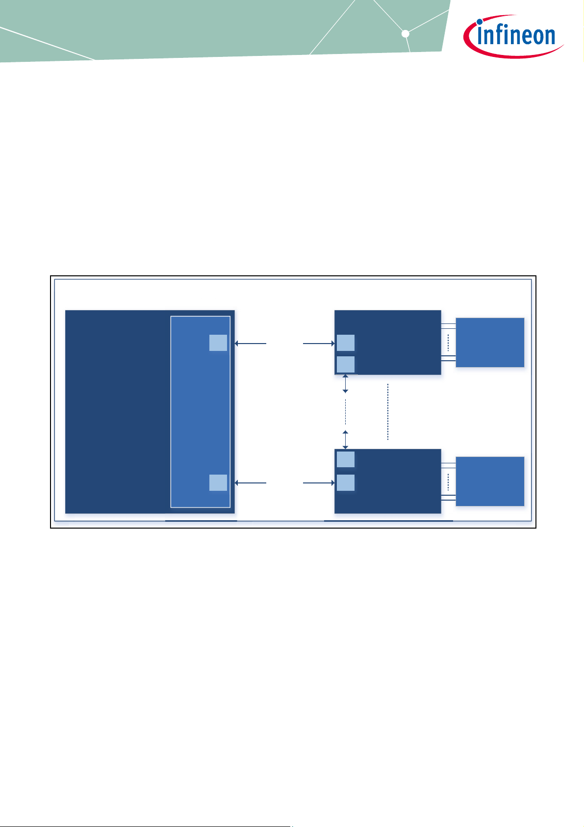
TLE9012
12- Channel
BMS Board
TLE9012AQU_DTR_
BMS2
TLE9012
12- Channel
BMS Board
TLE9012AQU_DTR_
BMS2
Aurix Application Kit
TC2xx
KIT_AURIX_TC265_TFT/
KIT_AURIX_TC397_TFT
Transceiver
Demo Board
TLE9015
TLE9015QU_
TRX_BRG
iso UART
iso UART
12 Cells/
Resistor ladder
12 Cells/
Resistor ladder
HS
LS
LS
HS
HS
LS
Infineon BMS Demo Kit TLE9012AQU
User Manual Demo Kit TLE9012AQU & TLE9015QU
User Manual Demo Kit
Li-Ion Battery Monitoring and Balancing IC
About this document
User Manual for multi-cell monitoring and balancing ICs TLE9012AQU & TLE9015QU evaluation kits designed
for Li-ion battery packs used in hybrid electric vehicles (HEV), plug-in hybrid electric vehicles (PHEV), battery
electric vehicles (BEV) as well as in stationary Lithium-Ion batteries.
Figure 1 Demo Kit BMS
Page 2

User Manual Demo Kit TLE9012AQU & TLE9015QU
Table of Contents
About this document . . . . . . . . . . . . . . . . . . . . . . . . . . . . . . . . . . . . . . . . . . . . . . . . . . . . . . . . . . . . . . 1
Table of Contents . . . . . . . . . . . . . . . . . . . . . . . . . . . . . . . . . . . . . . . . . . . . . . . . . . . . . . . . . . . . . . . . . 2
1 Getting started . . . . . . . . . . . . . . . . . . . . . . . . . . . . . . . . . . . . . . . . . . . . . . . . . . . . . . . . . . . . . . . . . . . 3
1.1 Hardware elements of the Demo Kit . . . . . . . . . . . . . . . . . . . . . . . . . . . . . . . . . . . . . . . . . . . . . . . . . . . . . . . . 3
1.2 Hardware connection . . . . . . . . . . . . . . . . . . . . . . . . . . . . . . . . . . . . . . . . . . . . . . . . . . . . . . . . . . . . . . . . . . . . . 3
1.3 13 wire setup . . . . . . . . . . . . . . . . . . . . . . . . . . . . . . . . . . . . . . . . . . . . . . . . . . . . . . . . . . . . . . . . . . . . . . . . . . . . . 4
1.4 Flashing the AURIX
1.4.1 DAS tool . . . . . . . . . . . . . . . . . . . . . . . . . . . . . . . . . . . . . . . . . . . . . . . . . . . . . . . . . . . . . . . . . . . . . . . . . . . . . . . 5
1.4.2 Memtool . . . . . . . . . . . . . . . . . . . . . . . . . . . . . . . . . . . . . . . . . . . . . . . . . . . . . . . . . . . . . . . . . . . . . . . . . . . . . . . 5
1.4.3 Flash the AURIX
2 Terminal . . . . . . . . . . . . . . . . . . . . . . . . . . . . . . . . . . . . . . . . . . . . . . . . . . . . . . . . . . . . . . . . . . . . . . . 10
TM
hardware kit . . . . . . . . . . . . . . . . . . . . . . . . . . . . . . . . . . . . . . . . . . . . . . . . . . . . . . . . . 5
TM
. . . . . . . . . . . . . . . . . . . . . . . . . . . . . . . . . . . . . . . . . . . . . . . . . . . . . . . . . . . . . . . . . . . . . . . 5
3 Revision History . . . . . . . . . . . . . . . . . . . . . . . . . . . . . . . . . . . . . . . . . . . . . . . . . . . . . . . . . . . . . . . . . 12
User Manual BMS Demo Kit 2 Rev. 1.0
2020-06-04
Page 3
LS
HS
User Manual Demo Kit TLE9012AQU & TLE9015QU
Getting started
1 Getting started
1.1 Hardware elements of the Demo Kit
Note: All different versions of the evaluation boards are compatible to each other and can be used in the same
daisy chain.
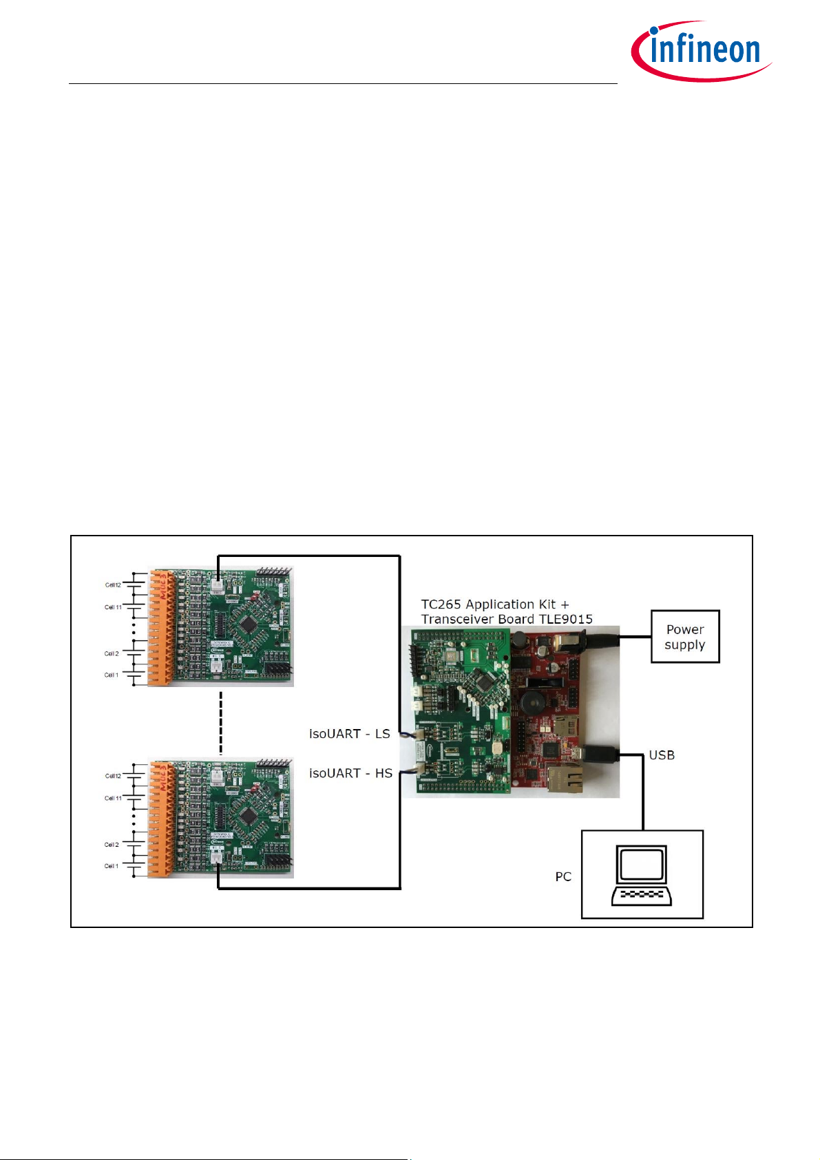
The following hardware is necessary to start with the TLE9012AQU Demo Kit:
• TLE9012AQU Demo Board
• at least 1x iso UART cable
• 1x resistor ladder (not necessary in evaluation board V5)
• TLE9015QU Transceiver Board
TM
• AURIX
• 12 V power supply
•USB cable
TC265 TFT Application Kit
• Power supply for resistor ladder (5 V - 60 V)
• optional: 12 Li-Ion cells (instead of resistor ladder)
Figure 2 Demo Kit BMS
1.2 Hardware connection
The hardware is connected as follow:
• The TLE9015QU transceiver board is plugged onto the AURIX
User Manual BMS Demo Kit 3 Rev. 1.0
TM
board (orientation as is Figure 2/Figure 3)
2020-06-04
Page 4
User Manual Demo Kit TLE9012AQU & TLE9015QU
Getting started
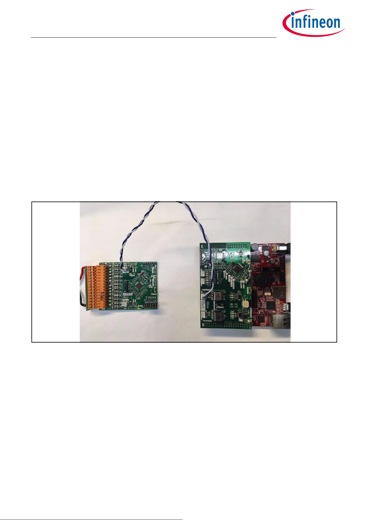
• Resistor ladder (cable with orange connector) is connected to the TLE9012AQU demo board (orange
connector) as shown in Figure 3 on the left side. In V5 of the evaluation kit, the resistor ladder is included
on the PCB and connected through a solder bump.
• Supply the resistor ladder with a voltage between 5 V - 60 V
• Supply the AURIX
• Use the iso UART cable (blue/white) cable to connect the transceiver board with the sensing board as
shown in Figure 3
Note: The sensing IC board can be connected either to cells or to a power supply with provided resistor ladder
(orange connector with red/black cable). If a resistance divider is used, an open load error is detected and
the corresponding bit in the diagnostsis register (GEN_DIAG) is set (because of that also cell balancing
ca nnot b e activ ated) . This is be cause the in terna l re sista nce of Li- Ion ce lls is muc h sm aller than t hat of the
resistors on the resistor divider. All other functions such as cell voltage measurement, temperature etc.
are possible without restriction.
TM
board with the 12 V power supply and connector it via the USB cable with the PC
Figure 3 Hardware setup
1.3 13 wire setup
The BMS sensing board can be used in a 13 wire or 15 wire setup (see details in App Note HW). For a 13 wire
setup, solder R13 and R29 with a 0 Ω resistor (0603 package) as descibed in Figure 4.
User Manual BMS Demo Kit 4 Rev. 1.0
2020-06-04
Page 5

User Manual Demo Kit TLE9012AQU & TLE9015QU
Getting started
Figure 4 13 wire setup
1.4 Flashing the AURIXTM hardware kit
The following steps are required to setup the frameword for the Demo Kit.
1.4.1 DAS tool
The DAS tool is a USB driver software provided by Infineon. It is required to connect the AURIXTM hardware kit
to the PC environment.
The latest version v7.1.8 can be found here:
Link to DAS tool
To start the installation, administrator privileges are requirement and the terms of use need to be accepted.
After successful installation of DAS, the PC should be able to detect the AURIX
in the device manager.
1.4.2 Memtool
The Memtool is a software from Infineon for on-chip flash programming.
The latest version v4.8.1 can be found here:
Link to Memtool
Click “Accept & Open” to download the software and run the installation afterwards.
TM
kit under the com port settings
1.4.3 Flash the AURIX
The AURIXTM kit needs to be connected to a 12 V power supply. A USB cable connects the board to the PC.
User Manual BMS Demo Kit 5 Rev. 1.0
TM
2020-06-04
Page 6

User Manual Demo Kit TLE9012AQU & TLE9015QU
Getting started
TM
Figure 5 AURIX
Press “START” button to initialize.
power supply and USB connection
TM
Figure 6 AURIX
Open the device manager and expand “Universal Serial Bus controllers”. Right click on “Infineon DAS JDS
COM” to open the properties. Select the tab “Advanced”, check “Load VCP” and click “OK”.
initialize
User Manual BMS Demo Kit 6 Rev. 1.0
2020-06-04
Page 7

User Manual Demo Kit TLE9012AQU & TLE9015QU
Getting started
Figure 7 Configuration of the COM port
Disconnect the USB cable and power supply and reconnect. After pressing “START”, check the COM port
number in the device manager by expandi ng “Por ts (COM &LPT)” . A port number is assi gned to th e AURIX
TM
kit.
Figure 8 Infineon DAS JDS COM port
Open the Memtool got to “Target” -> “Change...”.
Figure 9 Select Target Configuration
Click on “New” and select “Use a default target configuration”. Expand “TriCore Aurix” -> “Application Kits
(DAS)”. Select “Application Kit with TC267D B-Step(DAS)” as shown in Figure 10.
User Manual BMS Demo Kit 7 Rev. 1.0
2020-06-04
Page 8

User Manual Demo Kit TLE9012AQU & TLE9015QU
Getting started
Figure 10 Create or use default
Click “Finish” and save the target configuration file then select “OK”. After selecting the target configuration,
click on “Connect”. If connection is successful, you will be able to see this message “ready for Memtool
Command”. Click on “Open File ...”.
Figure 11 Memtool
Select the *.hex file “TLE9015QU_TLE9012AQU_Aurix1G_v3_Tricore.hex” stored on the USB stick. Click
“Select All” and afterwards “Add Sel”. To flash the AURIX
the message shown in Figure 12.
User Manual BMS Demo Kit 8 Rev. 1.0
TM
select “Program all”. Once successful, you can see
2020-06-04
Page 9

User Manual Demo Kit TLE9012AQU & TLE9015QU
Getting started
Figure 12 Execute Memtool command
Note: For further details or support on how to flash the AURIX
https://www.infineon.com/aurix
TM
TFT kit, please refer to
User Manual BMS Demo Kit 9 Rev. 1.0
2020-06-04
Page 10

User Manual Demo Kit TLE9012AQU & TLE9015QU
Terminal
2 Terminal
A terminal program (e.g. TeraTerm) can be used to communicate with the BMS IC. The configuration of the
serial port is shown in Figure 13.
Figure 13 Serial port setup
After successful configuration, a user manual is available by sending “?”.
Figure 14 User manual
There is the possibility to load a script into the terminal, which will perform several lines of commands. Drag
& drop can be used to load the script in the terminal. A script, which reads out all the cell voltage is provided
on the USB stick “TC265TFT_BMS_init_CVM_1_Slave_Terminal.txt”.
User Manual BMS Demo Kit 10 Rev. 1.0
2020-06-04
Page 11

User Manual Demo Kit TLE9012AQU & TLE9015QU
Terminal
Figure 15 Terminal script to read out all CVMs
The result registers can be copied into an Excel sheet to calculate the cell voltages (in mV) out of the hex
register values. Therefore, the lines shown in Figure 15 need to be marked and copied by selecting “Edit” ->
“Copy table”.
Based on the “C265TFT_BMS_init_CVM_1_Slave_Terminal.txt” file is an Excel sheet on the USB stick available
to calculate the voltages in mV. The Excel sheet is shown in Figure 16.
Figure 16 TLE9012AQU_CVM.xlsx Excel sheet to calculate the cell voltages in mV
User Manual BMS Demo Kit 11 Rev. 1.0
2020-06-04
Page 12

User Manual Demo Kit TLE9012AQU & TLE9015QU
Revision History
3 Revision History
Revision Date Changes
1.0 2020-06-04 Initial User Manual
User Manual BMS Demo Kit 12 Rev. 1.0
2020-06-04
Page 13

Trademarks of Infineon Technologies AG
All referenced product or service names and trademarks are the property of their respective owners.
IMPORTANT NOTICE
Edition 2020-06-04
Published by
Infineon Technologies AG
81726 Munich, Germany
© 2020 Infineon Technologies AG.
All Rights Reserved.
Do you have a question about any
aspect of this document?
Email: erratum@infineon.com
Document reference
The information contained in this application note is
given as a hint for the implementation of the product
only and shall in no event be regarded as a description
or warranty of a certain functionality, condition or
quality of the product. Before implementation of the
product, the recipient of this application note must
verify any function and other technical information
given herein in the real application. Infineon
Technologies hereby disclaims any and all warranties
and liabilities of any kind (including without limitation
warranties of non-infringement of intellectual
property rights of any third party) with respect to any
and all information given in this application note.
The data contained in this document is exclusively
intended for technically trained staff. It is the
responsibility of customer’s technical departments to
evaluate the suitability of the product for the intended
application and the completeness of the product
information given in this document with respect to
such application.
For further information on technology, delivery terms
and conditions and prices, please contact the nearest
Infineon Technologies Office (www.infineon.com).
WARNINGS
Due to technical requirements products may contain
dangerous substances. For information on the types
in question please contact your nearest Infineon
Technologies office.
Except as otherwise explicitly approved by Infineon
Technologies in a written document signed by
authorized representatives of Infineon Technologies,
Infineon Technologies’ products may not be used in
any applications where a failure of the product or any
consequences of the use thereof can reasonably be
expected to result in personal injury.
 Loading...