

Page 1

TLE5x09A16(D) Evaluation Kit
Analog AMR/GMR Angle Sensor Evaluation Kit
About this document
Scope and purpose
This document describes the Evaluation Kit for the TLE5x09A16(D) angle sensor. The purpose of this manual is
to describe the soware installation process and how to use the TLE5x09A16(D) angle sensor Evaluation Kit.
Intended audience
This document is intended for anyone who wants to use the TLE5x09A16(D) Evaluation Kit
Evaluation Kit Please read the Important Notice and Warnings at the end of this document Rev. 1.0
www.infineon.com 2020-06-12
Page 2

TLE5x09A16(D) Evaluation Kit
Analog AMR/GMR Angle Sensor Evaluation Kit
Table of contents
Table of contents
About this document . . . . . . . . . . . . . . . . . . . . . . . . . . . . . . . . . . . . . . . . . . . . . . . . . . . . . . . . . . . . . . . . . . . 1
Table of contents . . . . . . . . . . . . . . . . . . . . . . . . . . . . . . . . . . . . . . . . . . . . . . . . . . . . . . . . . . . . . . . . . . . . . . . 2
1 General description . . . . . . . . . . . . . . . . . . . . . . . . . . . . . . . . . . . . . . . . . . . . . . . . . . . . . . . . . . . . . . . . . . . . .3
2 Installation . . . . . . . . . . . . . . . . . . . . . . . . . . . . . . . . . . . . . . . . . . . . . . . . . . . . . . . . . . . . . . . . . . . . . . . . . . . . .4
3 Evaluation Kit for Angle Sensors . . . . . . . . . . . . . . . . . . . . . . . . . . . . . . . . . . . . . . . . . . . . . . . . . . . . . . . . .6
3.1 Connection to PC and starting the application . . . . . . . . . . . . . . . . . . . . . . . . . . . . . . . . . . . . . . . . . . . . . . 6
3.2 Connecting to the device . . . . . . . . . . . . . . . . . . . . . . . . . . . . . . . . . . . . . . . . . . . . . . . . . . . . . . . . . . . . . . . . . 6
3.3 TLE5x09A16(D) sensor panel . . . . . . . . . . . . . . . . . . . . . . . . . . . . . . . . . . . . . . . . . . . . . . . . . . . . . . . . . . . . . .7
3.4 Calibration panel . . . . . . . . . . . . . . . . . . . . . . . . . . . . . . . . . . . . . . . . . . . . . . . . . . . . . . . . . . . . . . . . . . . . . . . . 7
3.5 TLE5x09A16(D) sensor panel . . . . . . . . . . . . . . . . . . . . . . . . . . . . . . . . . . . . . . . . . . . . . . . . . . . . . . . . . . . . .10
3.6 Sensor config panel . . . . . . . . . . . . . . . . . . . . . . . . . . . . . . . . . . . . . . . . . . . . . . . . . . . . . . . . . . . . . . . . . . . . .11
3.7 TLE5x09A16(D) saved sensor acquired data . . . . . . . . . . . . . . . . . . . . . . . . . . . . . . . . . . . . . . . . . . . . . . . 11
Revision history . . . . . . . . . . . . . . . . . . . . . . . . . . . . . . . . . . . . . . . . . . . . . . . . . . . . . . . . . . . . . . . . . . . . . . . 13
Disclaimer . . . . . . . . . . . . . . . . . . . . . . . . . . . . . . . . . . . . . . . . . . . . . . . . . . . . . . . . . . . . . . . . . . . . . . . . . . . . 14
Evaluation Kit 2 Rev. 1.0
2020-06-12
Page 3

TLE5x09A16(D) Evaluation Kit
Analog AMR/GMR Angle Sensor Evaluation Kit
1 General description
1 General description
This kit is based on XMC™4700 platform. The kit is equipped with the TLE5x09A16(D) dual die angle sensor and a
FTDI chip that implements a high baud rate communication.
The EvalKit consists of:
• Dual Die Angle Sensors Evaluation Board
• Rotation knob (3D printed) with magnet (MTS SD-6x2.5-NI-N35SH)
The EvalKit does not contain:
• micro USB cable
Figure 1 Dual Die Angle Sensors Eval Kit with XMC™ 4700
Figure 2 Rotation knob with TLE5x09A16(D) angle sensor below
The Evaluation Kit includes a GUI soware application that can be downloaded from the Evaluation Kit product
page
Evaluation Kit 3 Rev. 1.0
2020-06-12
Page 4
TLE5x09A16(D) Evaluation Kit
Analog AMR/GMR Angle Sensor Evaluation Kit
2 Installation
2 Installation
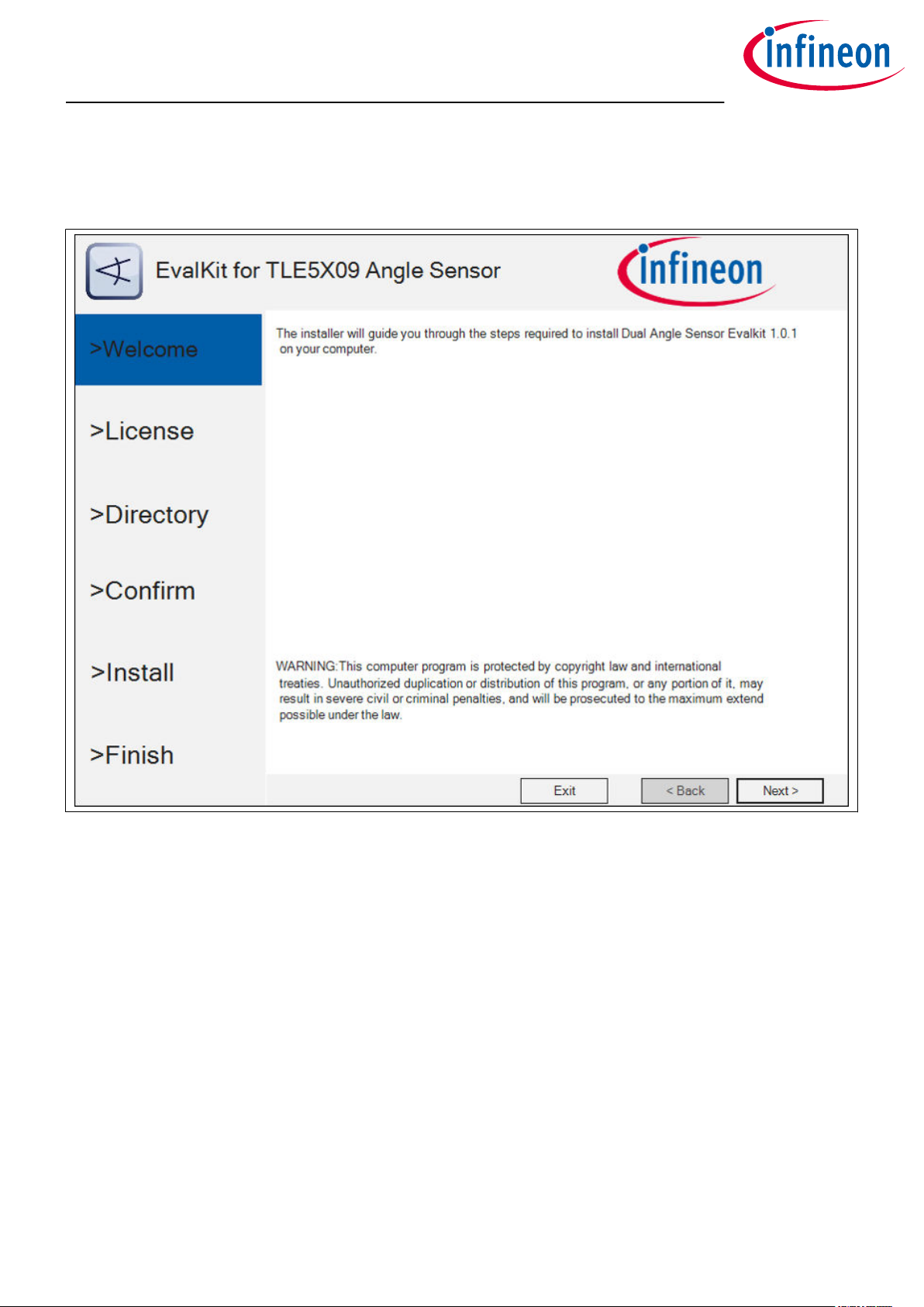
This is the installer entry point.
Figure 3 Installer entry point
1. Click Next to go forward with the process
2. Please read the license agreement
a. Check the “I accept the terms in the License Agreement” checkbox
b. The “Next” button activates only aer agreeing with the terms
3. Directory for the soware installation
a. You may select the installation folder – recommended is to leave the default installation path
b. You may select if a desktop icon is generated or not
c. The hardware device may only operate on a computer that has the FTDI driver installed
d. The Soware GUI is built in .NET environment 4.5. A check is being done for compatibility and you
may choose to install (if not already installed) the .NET framework 4.7 (web installer – requires
connection to internet)
4. Confirm the installation process
5. Beginning of the installation process
a. Windows UAC (user access control) will prompt for access confirmation
b. Depending on the security settings, you may need administration rights on the installation
machine
c. Wait for the installation process to finish
6. Beginning ot the FTDI driver installation process
Evaluation Kit 4 Rev. 1.0
2020-06-12
Page 5

TLE5x09A16(D) Evaluation Kit
Analog AMR/GMR Angle Sensor Evaluation Kit
2 Installation
7. Device driver installation Wizard
a. This wizard helps you install the soware drivers that some computers devices need in order to
work
b. Click next to continue
8. Please read the license agreement and check the “I accept this agreement” checkbox. The “Next” button
activates only aer agreeing with the terms
9. Finalize the installation by clicking Finish
a. Check the message provided by the installer. In case of errors, the Soware will not be available
for running
Evaluation Kit 5 Rev. 1.0
2020-06-12
Page 6

1
2
3
TLE5x09A16(D) Evaluation Kit
Analog AMR/GMR Angle Sensor Evaluation Kit
3 Evaluation Kit for Angle Sensors
3 Evaluation Kit for Angle Sensors
3.1 Connection to PC and starting the application
Connect the hardware to PC using a USB to Micro-USB cable
Start the application (via shortcut on desktop or Start → All Programs → Infineon Technologies → Dual Angle
Sensor Evalkit)
1: This GUI component will show any connected
devices. You may select the device and open a
connection / flash the device.
Note: Press the ´Connect´Button to go on. There
are three buttons available: Connect,
disconnect, refresh
2: You may select the sensor type via the combo-box
and start/stop acquisition.
3: Sensor panel – will be displayed aer valid sensor is
being selected by the user.
3.2 Connecting to the device
While connecting to the device, the animated picture
with rotating gears will appear.
The soware will check the firmware version and flash
if it needs to be updated.
The picture will disappear when the process is
complete and the device is ready.
Evaluation Kit 6 Rev. 1.0
2020-06-12
Page 7

TLE5x09A16(D) Evaluation Kit
Analog AMR/GMR Angle Sensor Evaluation Kit
3 Evaluation Kit for Angle Sensors
3.3 TLE5x09A16(D) sensor panel
Aer selecting the sensor from the drop down list, the
sensor panel will appear.
You can now start the data acquisition. All controls
(Settings, Calibration Panel, Save, Clear) become
available only if data acquisition is stopped.
3.4 Calibration panel
The raw signals of the analog angle sensor TLE5x09A16(D) have to be calibrated to achieve high angle accuracy.
A calibration of amplitude, oset and non-orthogonality has to be done when the sensor is used the first time
(end-of-line calibration).
When the panel opens the final parameters used for angle calibration are read from the microcontroller.
In this panel the user can start the sensor calibration procedure. Every start will reset the existing calibration
parameters stored on the microcontroller.
Below the circle quadrants, instruction messages are displayed.
Evaluation Kit 7 Rev. 1.0
2020-06-12
Page 8

TLE5x09A16(D) Evaluation Kit
Analog AMR/GMR Angle Sensor Evaluation Kit
3 Evaluation Kit for Angle Sensors
Press Start to beginn.
Rotate the knob slowly counter clockwise.
Rotate the knob slowly clockwise.
Calibration finished.
Evaluation Kit 8 Rev. 1.0
2020-06-12
Page 9

TLE5x09A16(D) Evaluation Kit
Analog AMR/GMR Angle Sensor Evaluation Kit
3 Evaluation Kit for Angle Sensors
Aer the calibration process is complete, the user can read and save the calibration parameters stored on the
microcontroller.
In the panel are displayed only the final parameters used for angle calibration. By clicking “Open Last File”, the
user can access the full parameters list stored on a csv file at every “Read and Save”.
The example in Figure 4 shows the calibration parameters amplitude, oset and non-orthogonality of
TLE5309(D) sensor. The X value corresponds to the cosine output while the Y value corresponds to the sine.
The GMR sensor is placed on the top and the AMR sensor on the bottom of the package. The bottom sensor is in
flipped configuration compared to the top sensor in TLE5x09A16(D) dual die variants.
Figure 4 Calibration panel
Files are saved in the computer: “C:\Users\<user>\AppData\Local\InfineonDualAnalogAngleTemp”
The calibration procedure is done on the microcontroller with the “Library for One Time Calibration &
Compensation”.
Evaluation Kit 9 Rev. 1.0
2020-06-12
Page 10

TLE5x09A16(D) Evaluation Kit
Analog AMR/GMR Angle Sensor Evaluation Kit
3 Evaluation Kit for Angle Sensors
Figure 5 Parameter list of calibration process
3.5 TLE5x09A16(D) sensor panel
The TLE5x09A16(D) eval kit displays real-time angle values.
Aer the sensor is fully calibrated, the calibrated angle value will be displayed.
The user can click and pin a cursor in the signal chart. If the checkbox “Enable Cursor Snap” is checked, the
cursor will point to the nearest signal value. The cursor value is displayed in the right corner box.
The user can also zoom into the chart by using mouse scroll.
Evaluation Kit 10 Rev. 1.0
2020-06-12
Page 11

TLE5x09A16(D) Evaluation Kit
Analog AMR/GMR Angle Sensor Evaluation Kit
3 Evaluation Kit for Angle Sensors
Figure 6 Sensor panel
3.6 Sensor config panel
This panel can be accessed while data acquisition is stopped at Settings → Sensor Config.
The user can select a predefined acquisition rate for the sensor data read. Lowering the rate will reduce the
required processing power (on the microcontroller and computer).
Figure 7 Sensor confi panel
3.7 TLE5x09A16(D) saved sensor acquired data
All sensor acquired data can be saved in a csv file, by pressing “Save” button from the sensor panel.
Evaluation Kit 11 Rev. 1.0
2020-06-12
Page 12

TLE5x09A16(D) Evaluation Kit
Analog AMR/GMR Angle Sensor Evaluation Kit
3 Evaluation Kit for Angle Sensors
Figure 8 Sensor acquired data
Evaluation Kit 12 Rev. 1.0
2020-06-12
Page 13

TLE5x09A16(D) Evaluation Kit
Analog AMR/GMR Angle Sensor Evaluation Kit
Revision history
Revision history
Revision Date Changes
Rev. 1.0 2020-06-17 • Initial creation
Evaluation Kit 13 Rev. 1.0
2020-06-12
Page 14

Trademarks
All referenced product or service names and trademarks are the property of their respective owners.
Edition 2020-06-12
Published by
Infineon Technologies AG
81726 Munich, Germany
©
2020 Infineon Technologies AG
All Rights Reserved.
Do you have a question about any
aspect of this document?
Email: erratum@infineon.com
Document reference
IFX-lpa1591258043489
IMPORTANT NOTICE
The information given in this document shall in no
event be regarded as a guarantee of conditions or
characteristics (“Beschaenheitsgarantie”) .
With respect to any examples, hints or any typical values
stated herein and/or any information regarding the
application of the product, Infineon Technologies
hereby disclaims any and all warranties and liabilities of
any kind, including without limitation warranties of
non-infringement of intellectual property rights of any
third party.
In addition, any information given in this document is
subject to customer’s compliance with its obligations
stated in this document and any applicable legal
requirements, norms and standards concerning
customer’s products and any use of the product of
Infineon Technologies in customer’s applications.
The data contained in this document is exclusively
intended for technically trained sta. It is the
responsibility of customer’s technical departments to
evaluate the suitability of the product for the intended
application and the completeness of the product
information given in this document with respect to such
application.
WARNINGS
Due to technical requirements products may contain
dangerous substances. For information on the types
in question please contact your nearest Infineon
Technologies oice.
Except as otherwise explicitly approved by Infineon
Technologies in a written document signed by
authorized representatives of Infineon Technologies,
Infineon Technologies’ products may not be used in
any applications where a failure of the product or
any consequences of the use thereof can reasonably
be expected to result in personal injury
 Loading...