

Page 1
TLE493D-A2B6 MS2GO
3D Magnetic Sensor 2 Go evaluation kit
User Manual
About this document
Scope and purpose
This document provides an introduction to the 3D Magnetic Sensor 2 Go kit and should enable the reader to
eiciently carry out own evaluations with the 3D magnetic sensor TLE493D-A2B6.
Intended audience
This document is aimed at everyone who wants to work with the 3D Magnetic Sensor 2 Go evaluation kit.
User Manual Please read the Important Notice and Warnings at the end of this document 1.2
www.infineon.com 2019-09-06
Page 2

TLE493D-A2B6 MS2GO
3D Magnetic Sensor 2 Go evaluation kit
Table of contents
Table of contents
User Manual . . . . . . . . . . . . . . . . . . . . . . . . . . . . . . . . . . . . . . . . . . . . . . . . . . . . . . . . . . . . . . . . . . . . . . . . . . . .1
About this document . . . . . . . . . . . . . . . . . . . . . . . . . . . . . . . . . . . . . . . . . . . . . . . . . . . . . . . . . . . . . . . . . . . 1
Table of contents . . . . . . . . . . . . . . . . . . . . . . . . . . . . . . . . . . . . . . . . . . . . . . . . . . . . . . . . . . . . . . . . . . . . . . . 2
1 Introduction . . . . . . . . . . . . . . . . . . . . . . . . . . . . . . . . . . . . . . . . . . . . . . . . . . . . . . . . . . . . . . . . . . . . . . . . . . . 3
1.1 Hardware overview . . . . . . . . . . . . . . . . . . . . . . . . . . . . . . . . . . . . . . . . . . . . . . . . . . . . . . . . . . . . . . . . . . . . . . 3
1.2 Soware . . . . . . . . . . . . . . . . . . . . . . . . . . . . . . . . . . . . . . . . . . . . . . . . . . . . . . . . . . . . . . . . . . . . . . . . . . . . . . . .3
1.3 Hardware extensions . . . . . . . . . . . . . . . . . . . . . . . . . . . . . . . . . . . . . . . . . . . . . . . . . . . . . . . . . . . . . . . . . . . . 4
2 EvalBoard description . . . . . . . . . . . . . . . . . . . . . . . . . . . . . . . . . . . . . . . . . . . . . . . . . . . . . . . . . . . . . . . . . . 7
2.1 Optional external power supply . . . . . . . . . . . . . . . . . . . . . . . . . . . . . . . . . . . . . . . . . . . . . . . . . . . . . . . . . . . 7
2.2 Pin header connector . . . . . . . . . . . . . . . . . . . . . . . . . . . . . . . . . . . . . . . . . . . . . . . . . . . . . . . . . . . . . . . . . . . . 8
2.3 EvalBoard schematics . . . . . . . . . . . . . . . . . . . . . . . . . . . . . . . . . . . . . . . . . . . . . . . . . . . . . . . . . . . . . . . . . . . .9
3 Soware installation . . . . . . . . . . . . . . . . . . . . . . . . . . . . . . . . . . . . . . . . . . . . . . . . . . . . . . . . . . . . . . . . . . 13
3.1 Driver installation . . . . . . . . . . . . . . . . . . . . . . . . . . . . . . . . . . . . . . . . . . . . . . . . . . . . . . . . . . . . . . . . . . . . . . 16
4 3D magnetic sensor evaluation . . . . . . . . . . . . . . . . . . . . . . . . . . . . . . . . . . . . . . . . . . . . . . . . . . . . . . . . .20
4.1 Getting started . . . . . . . . . . . . . . . . . . . . . . . . . . . . . . . . . . . . . . . . . . . . . . . . . . . . . . . . . . . . . . . . . . . . . . . . .20
4.2 Graph View . . . . . . . . . . . . . . . . . . . . . . . . . . . . . . . . . . . . . . . . . . . . . . . . . . . . . . . . . . . . . . . . . . . . . . . . . . . . 21
4.3 Joystick view . . . . . . . . . . . . . . . . . . . . . . . . . . . . . . . . . . . . . . . . . . . . . . . . . . . . . . . . . . . . . . . . . . . . . . . . . . 22
4.4 Rotation view . . . . . . . . . . . . . . . . . . . . . . . . . . . . . . . . . . . . . . . . . . . . . . . . . . . . . . . . . . . . . . . . . . . . . . . . . . 22
4.5 Linear movement . . . . . . . . . . . . . . . . . . . . . . . . . . . . . . . . . . . . . . . . . . . . . . . . . . . . . . . . . . . . . . . . . . . . . . 23
4.6 Out of sha . . . . . . . . . . . . . . . . . . . . . . . . . . . . . . . . . . . . . . . . . . . . . . . . . . . . . . . . . . . . . . . . . . . . . . . . . . . . 24
5 Example code for developers . . . . . . . . . . . . . . . . . . . . . . . . . . . . . . . . . . . . . . . . . . . . . . . . . . . . . . . . . . .26
6 XMC for Arduino . . . . . . . . . . . . . . . . . . . . . . . . . . . . . . . . . . . . . . . . . . . . . . . . . . . . . . . . . . . . . . . . . . . . . . . 27
Revision history . . . . . . . . . . . . . . . . . . . . . . . . . . . . . . . . . . . . . . . . . . . . . . . . . . . . . . . . . . . . . . . . . . . . . . . 28
Disclaimer . . . . . . . . . . . . . . . . . . . . . . . . . . . . . . . . . . . . . . . . . . . . . . . . . . . . . . . . . . . . . . . . . . . . . . . . . . . . 29
User Manual 2 1.2
2019-09-06
Page 3
TLE493D-A2B6 MS2GO
3D Magnetic Sensor 2 Go evaluation kit
Introduction
1 Introduction
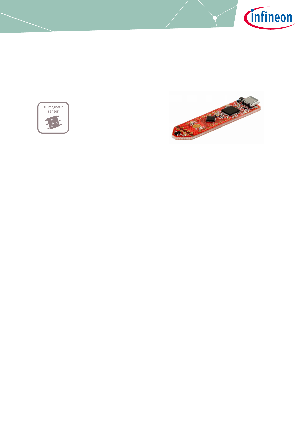
Infineon’s 3D Magnetic Sensor 2 Go is a compact evaluation kit to familiarize the user with the 3D Hall sensor
TLE493D-A2B6. In a short time the board is set up and own 3D magnetic measurements can be executed. All
required hardware is included and the soware can be downloaded for free from the Infineon web page.
This user manual describes the dierent parts of the board, the soware installation process and clarifies how
the Graphical User Interface (GUI) can be used to do first evaluations. Further it is shown where to find example
code and an Arduino library as a easy starting point for own developments.
1.1 Hardware overview
The 3D Magnetic Sensor 2 Go kit contains:
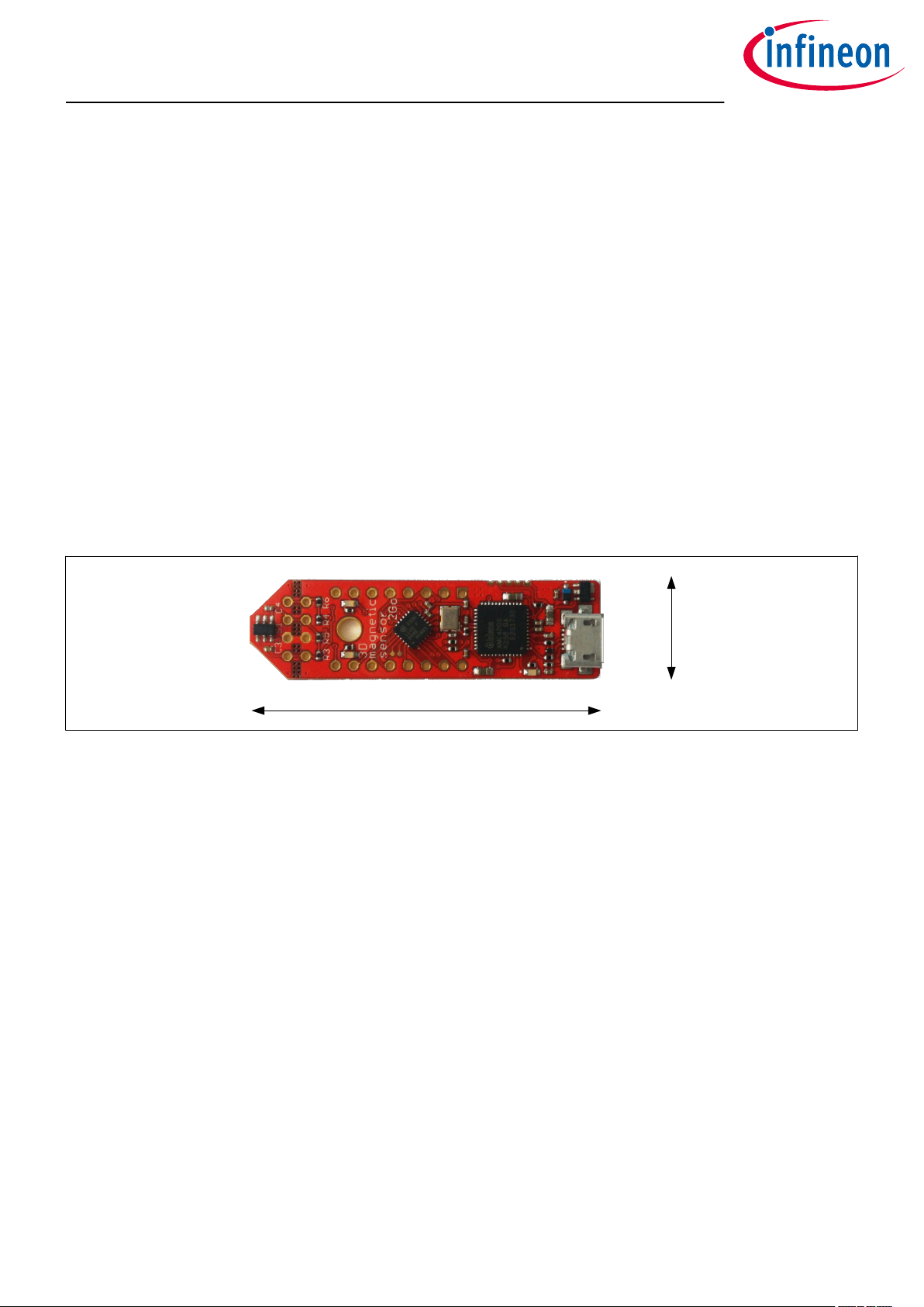
• The 3D evaluation board (EvalBoard) as shown in Figure 1, a ready-to-use printed circuit board (PCB) with
the 3D Hall sensor. The EvalBoard is based on the XMC2Go-Kit. More technical documents and detailed
description can be found at http://www.infineon.com/xmc2go
• A standalone 7x7x5 mm ferrite block magnet
To use the 3D Magnetic Sensor 2 Go kit the user has to acquire a USB cable with a micro USB connection-end for
the EvalBoard side and a conventional USB connection for the PC side.
14mm
50mm
Figure 1 3D Magnetic Sensor 2 Go EvalBoard
1.2
The required soware to run the kit can be found at the Infineon web site. For further information refer to the
chapter Soware installation.
The soware package contains:
• A Graphical User Interface (GUI) for sensor evaluation.
• Firmware to be flashed into the XMC microcontroller for the low level communication with the sensor.
• USB driver J-Link from Segger which is necessary to establish the USB connection.
This soware was designed to be used with Windows 7 and Windows 10. It is compatible with both 32-bit and
64-bit system types. Backward compatibility with older Windows versions is ensured only by the .NET platform
as specific tests were not conducted on older operating systems.
The USB protocols capabilities are defined by the Segger driver. Versions USB 2.0 and USB 3.0 are compatible.
The GUI is used to enable a communication between the sensor and the PC. The user can configure the sensor
to operate in dierent modes. In those modes the update rate of the magnetic field measured (X, Y and Z
components) and current consumption vary.
Soware
User Manual 3 1.2
2019-09-06
Page 4
TLE493D-A2B6 MS2GO
3D Magnetic Sensor 2 Go evaluation kit
Introduction
1.3 Hardware extensions
Additionally to the provided standalone magnet there are several dedicated extensions available that can be
mounted to the 3D Magnetic Sensor 2 Go kit.
Table 1 3D Magnetic Sensor 2 Go extensions
Type Orderable part number (OPN)
Joystick JOYSTICKFOR3D2GOKITTOBO1
Rotation knob ROTATEKNOB3D2GOKITTOBO1
Linear slider LINEARSLIDER2GOTOBO1
Out of sha OUTOFSHAFTFOR3D2GOTOBO1
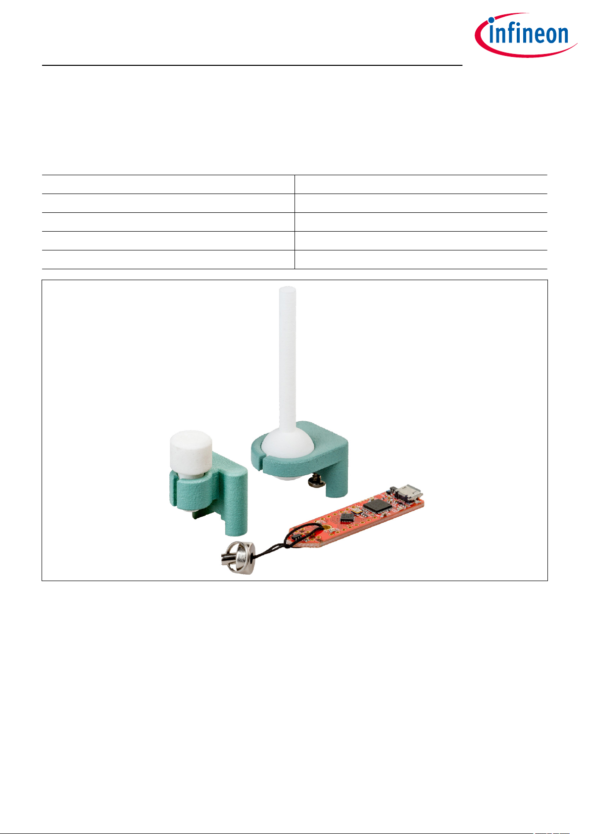
Figure 2 Joystick and rotation knob extensions for the 3D Magnetic Sensor 2 Go kit
Joystick
The magnet used in the joystick extension is an axial magnetized magnet as shown in Figure 3. The magnet
material is ferrite, of class Y35, which is equivalent to a remanence of between 400 mT and 410 mT. The magnet
disk has a size of 5 mm diameter and 5 mm thickness. For more information about the magnet, please follow
this link:
https://www.supermagnete.de/eng/disc-magnets-ferrite/disc-magnet-5mm-5mm_FE-S-05-05
User Manual 4 1.2
2019-09-06
Page 5
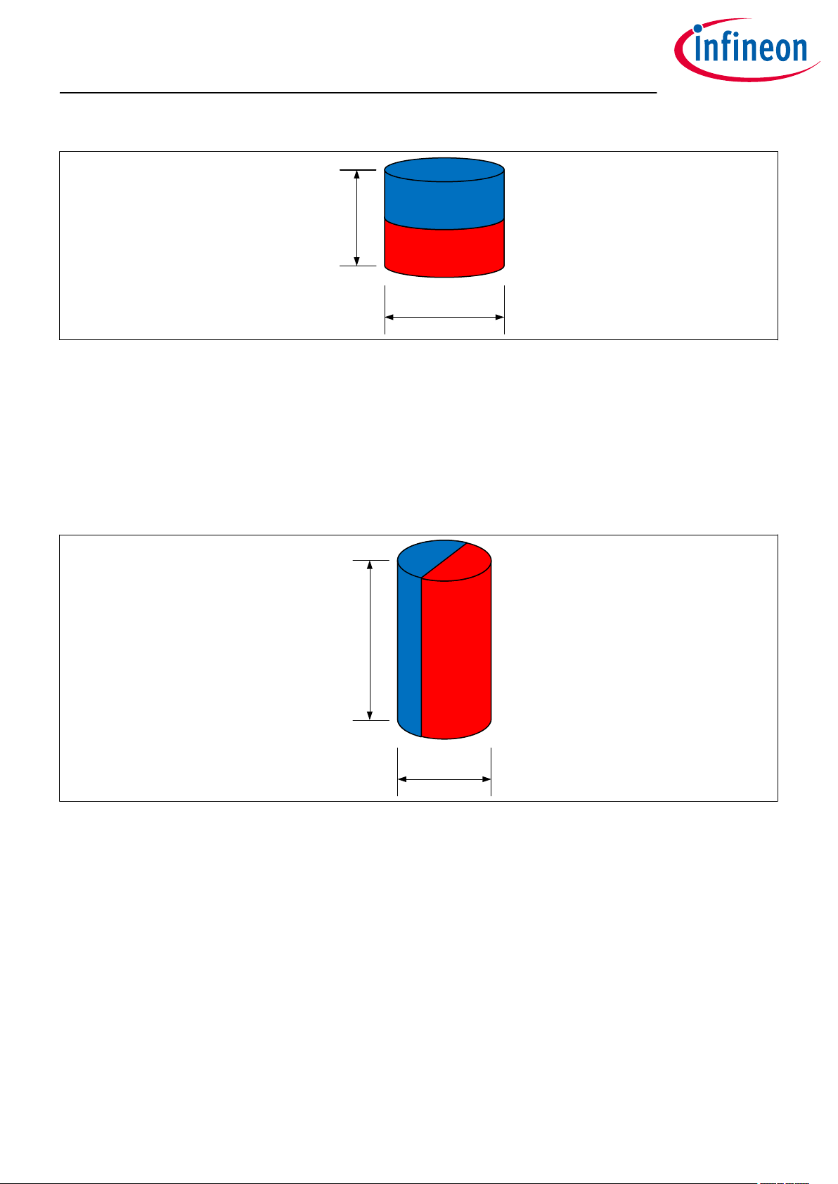
5 mm
5 mm
10 mm
4 mm
TLE493D-A2B6 MS2GO
3D Magnetic Sensor 2 Go evaluation kit
Introduction
Figure 3 Magnet used in the Joystick extension
Rotation knob
The magnet used in the rotate knob extension is a diametrically magnetized magnet as shown in Figure 4. The
magnet material is Neodymium Iron Boron (NdFeB) of class N45. The magnet is protected against corrosion
with Nickel coating (Ni-Cu-Ni). The magnet size is 4 mm diameter and 10 mm thickness. For more information
about the magnet, please follow this link:
https://www.supermagnete.de/eng/rod-magnets-neodymium/rod-magnet-diameter-4mm-height-10mmneodymium-n45-nickel-plated_S-04-10-DN
Figure 4 Magnet used in the rotation knob extension
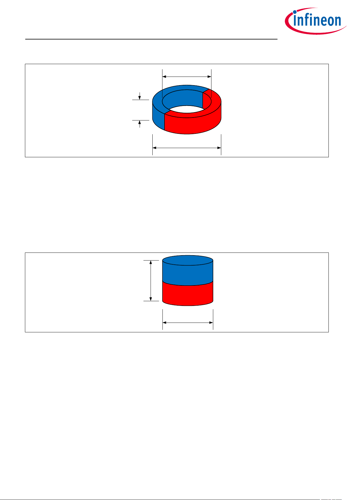
Out of sha
The magnet used in the out of sha extension is a diametrically magnetized ring magnet as shown in Figure 5 .
The magnet material is Neodymium Iron Boron (NdFeB) of class N45. The magnet is protected against corrosion
with Nickel coating (Ni-Cu-Ni). The magnet size is 10 mm outer diameter, 7 mm inner diameter and 3 mm
thickness. For more information about the magnet, please follow this link:
https://www.supermagnete.de/eng/ring-magnets-neodymium/ring-magnet-10mm-7mm-3mm_R-10-07-03DN
User Manual 5 1.2
2019-09-06
Page 6
10 mm
7 mm
3 mm
5 mm
5 mm
TLE493D-A2B6 MS2GO
3D Magnetic Sensor 2 Go evaluation kit
Introduction
Figure 5 Magnet used in the out of sha extension
Linear slider
The linear slider extension comes with two axial magnetized magnets of the same size as shown in Figure 6. The
first magnet material is Neodymium Iron Boron (NdFeB) of class N45. The magnet is protected against corrosion
with Nickel coating (Ni-Cu-Ni). The second magnet material is ferrite, of class Y35, which is equivalent to a
remanence of between 400 mT and 410 mT. Both magnet disk has a size of 5 mm diameter and 5 mm thickness.
For more information about the magnets, please follow this links:
https://www.supermagnete.de/eng/disc-magnets-neodymium/disc-magnet-5mm-5mm_S-05-05-N
https://www.supermagnete.de/eng/disc-magnets-ferrite/disc-magnet-5mm-5mm_FE-S-05-05
Figure 6 Magnet used in the linear slider extension
User Manual 6 1.2
2019-09-06
Page 7
TLE493D-A2B6 MS2GO
3D Magnetic Sensor 2 Go evaluation kit
EvalBoard description
2 EvalBoard description
The evaluation board (EvalBoard) is a ready-to-use printed circuit board (PCB) which contains:
• The 3D magnetic sensor TLE493D-A2B6. For the availability of 3D Magnetic Sensor 2 Go kits with dierent
sensor variants check the Infineon web page: https://www.infineon.com/cms/en/product/sensor/
magnetic-sensors/magnetic-position-sensors/3d-magnetics/
• XMC1100 microcontroller based on ARM Cortex™-M0 at 48 MHz frequency connected to the 3D sensor.
• XMC4200 microcontroller based on ARM Cortex™-M4 at 144 MHz frequency used for debugging and USB
communication.
• Micro USB connector for power supply and communication with the Graphical User Interface (GUI).
• LED for indication of power supply and debugging.
• Two LEDs for user configuration.
• Voltage regulator, reverse current protection diode and ESD protection diode.
• Pin headers to access data lines (e.g. via oscilloscope, external microcontroller).
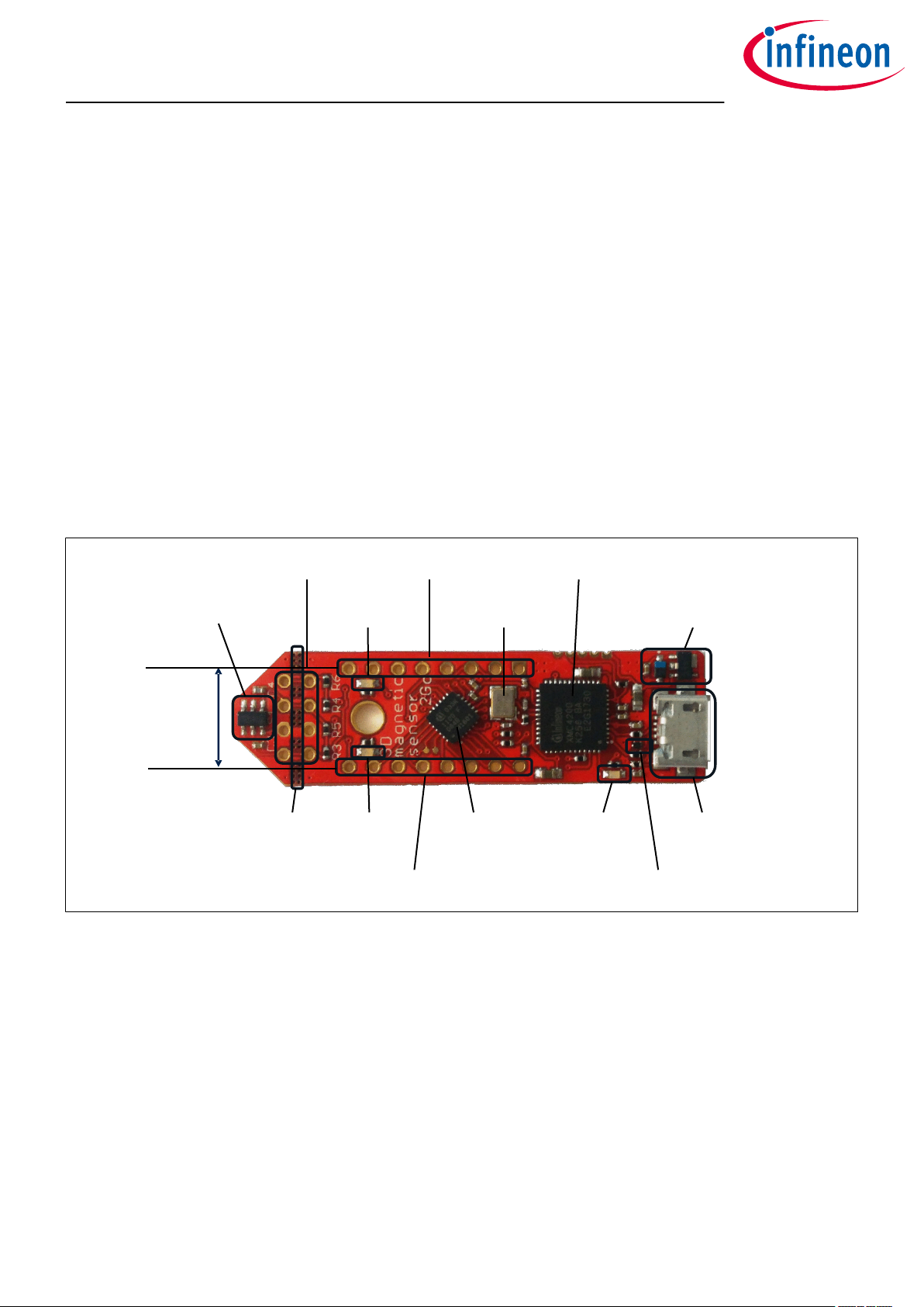
The dierent components and its location are shown in Figure 7. The 3D magnetic sensor can be separated
from the rest of the EvalBoard by cutting the break line.
TLE493D-A2B6
pin header
distance fits
to breadbord
pin header X3
user LED2
break
line
user LED1
pin header X1
@P1.1
@P0.12
pin header X2
crystal for
debug IC
XMC 1100
mircocontroller
Figure 7 Main components of the EvalBoard
2.1 Optional external power supply
XMC4200 debug IC and
UART to USB bridge
voltage regulator and reverse
current protection diode
power and
debug LED
ESD protection
diode
mirco USB
connector
The 3D Magnetic Sensor 2 Go EvalBoard is supplied via the USB cable. It is also possible to provide an external
power supply. If this is the case, a few considerations must be taken into account as described below.
The 3D Magnetic Sensor 2 Go EvalBoard must be supplied by external 5 Volt DC power supply connected to the
micro USB plug. The voltage regulator shis the voltage level to 3.3 V for the microcontrollers and the 3D
magnetic sensor. The Power & Debug LED indicates that the presence of the generated 3.3 V supply voltage.
Out of the box with the pre-programmed application and the on-board debugger in operation the EvalBoard
typically draws about 75 mA. This current can be delivered via the USB plug of a PC, which is specified to deliver
up to 500 mA. An on-board reverse current protection diode will ensure safe operation and protects the USB
port of the Laptop/PC in case power is provided through the pin header X1.
User Manual 7 1.2
2019-09-06
Page 8
TLE493D-A2B6 MS2GO
3D Magnetic Sensor 2 Go evaluation kit
EvalBoard description
It is not recommended to apply an additional power supply to the VDD pin of X1 (3.3 V) when the board is
powered via USB, because the 3.3 V supply could drive against the on-board power supply. The VDD pin can be
used to power an external circuit. But care must be taken not to draw more current than 150 mA, which is the
maximum current the on-board voltage regulator can deliver. Aer power-up the Debug LED starts blinking. In
case there is connection to a PC with correctly installed drivers, the Debug LED will turn from blinking to
constant illumination.
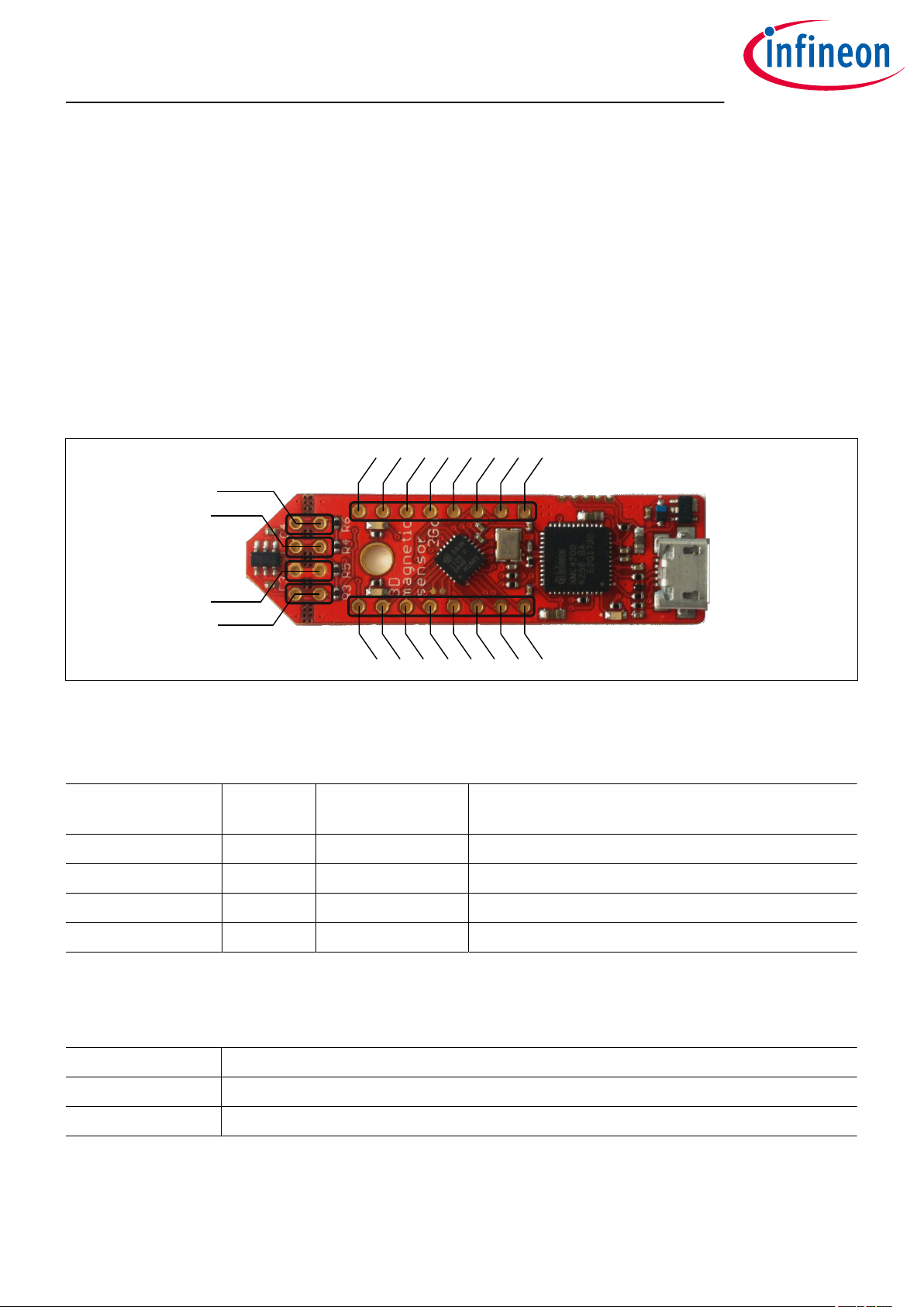
2.2 Pin header connector
The pin headers X1 and X2 can be used to extend the evaluation board or to perform measurements on the
XMC1100. The order of pins available at X1 and X2 corresponds to the pinning schema of the XMC1100
microcontroller in the TSSOP-16 pin package. The pinning table is also printed onto the bottom side of the PCB
(depending on the version). The pin header X3 can be used to access directly the 3D magnetic sensor pins.
P2.9
SDA (P2.10)
SCL (P2.11)
X3
X1
P0.5
P0.0
3.3 V
GND
P2.11
P2.10
P2.7
GND
V
DD
(P1.0)
X2
P0.6
P0.7
P0.8
P0.9
P0.14
P0.15
P2.0
P2.6
Figure 8 EvalBoard pin header connectors
The 3D Hall sensor pins can be accessed via the pin headers as shown in Table 2.
Table 2 Pin header description for the 3D magnetic sensor (X3)
TLE493D-A2B6 pin
number
Pin name
on board
XMC1100 port pin Sensor pin description
1 SCL P2.11 Interface clock and \INT pin, open drain
3 GND GND Ground pin
4 +3V3 P1.0 Supply pin
6 SDA P2.10 Interface data pin, open drain
The XMC1100 port pins P0.12 and P1.1 are connected the two user LEDs and are not available on the pin
headers.
Table 3 Pins used for the user LEDs
LED XMC1100 port pin
LED1 P0.12
LED2 P1.1
User Manual 8 1.2
2019-09-06
Page 9
TLE493D-A2B6 MS2GO
3D Magnetic Sensor 2 Go evaluation kit
EvalBoard description
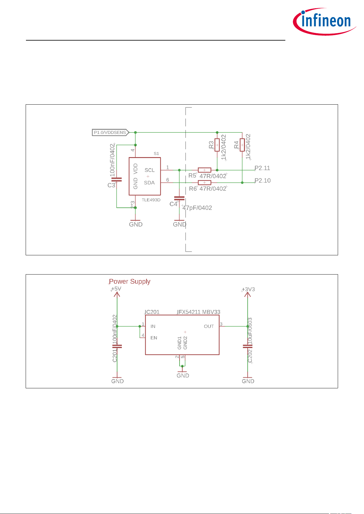
2.3 EvalBoard schematics
The schematics of the dierent blocks from the EvalBoard of the3D Magnetic Sensor 2 Go kit are provided in
this chapter. They can be used to design customized PCBs. The user (integrator) is responsible for the correct
functioning on system level as well as for the validation and testing.
Figure 9 EvalBoard schematic: 3D magnetic sensor
Figure 10 EvalBoard schematic: the voltage regulator (for the power supply)
User Manual 9 1.2
2019-09-06
Page 10

TLE493D-A2B6 MS2GO
3D Magnetic Sensor 2 Go evaluation kit
EvalBoard description
Figure 11 EvalBoard schematic: the LEDs for user configuration (connected to XMC1100 pins)
Figure 12 EvalBoard schematic: the XMC1100 microcontroller and pin headers
User Manual 10 1.2
2019-09-06
Page 11

TLE493D-A2B6 MS2GO
3D Magnetic Sensor 2 Go evaluation kit
EvalBoard description
Figure 13 Sketch of the debug connection
User Manual 11 1.2
2019-09-06
Page 12

TLE493D-A2B6 MS2GO
3D Magnetic Sensor 2 Go evaluation kit
EvalBoard description
Figure 14 EvalBoard schematic: the XMC4200 microcontroller and micro USB connector
User Manual 12 1.2
2019-09-06
Page 13

TLE493D-A2B6 MS2GO
3D Magnetic Sensor 2 Go evaluation kit
Soware installation
3 Soware installation
The following description guides through the installation procedure of the free evaluation soware for the 3D
Magnetic Sensor 2 Go kit.
Steps
1. Download the soware.
Follow the link below to reach the Sensor 2 Go information page on the Infineon website. As shown in
Figure 15, you can find the download link for the latest version of the 3D Magnetic Sensor 2 Go GUI on
the right hand side.
https://www.infineon.com/cms/en/product/promopages/sensors-2go/
Figure 15 Download the "3D Magnetic Sensor 2 Go" soware from the Infineon web
page
2. Start the installation process.
Browse to your download folder and extract the downloaded .zip file. Aerwards, double click on
the .msi file to start the installer. The window in Figure 16 pops up. Click "Next".
User Manual 13 1.2
2019-09-06
Page 14

TLE493D-A2B6 MS2GO
3D Magnetic Sensor 2 Go evaluation kit
Soware installation
Figure 16 Start the soware installation
3. Read the license agreement carefully and tick the box to accept the terms. Click Next.
Figure 17 Accept the license agreement
4. Choose your installation path. The soware requires the SEGGER J-Link driver and .NET framework
version 4.5 or later to be installed on your PC. If not yet available, check the respective items. Click Next
User Manual 14 1.2
2019-09-06
Page 15

TLE493D-A2B6 MS2GO
3D Magnetic Sensor 2 Go evaluation kit
Soware installation
Figure 18 Select you installation folder
5. Confirm the installation settings by clicking on Install.
Figure 19 Confirm the installation
6. Once the installation is complete, click on Finish to close the installer.
User Manual 15 1.2
2019-09-06
Page 16

TLE493D-A2B6 MS2GO
3D Magnetic Sensor 2 Go evaluation kit
Soware installation
Figure 20 Installation finished
7. You can now start the evaluation soware. Open the start menu, browse to Infineon Technologies > 3D
Sensor 2go Kit and open the application by clicking on 3D 2Go.
Figure 21 Shortcut to the 3D Magnetic 2Go evaluation soware (GUI)
3.1 Driver installation
To enable the communication between the 3D Magnetic Sensor 2 Go kit it is necessary to install the J-Link driver
on your PC.
The driver is included in the GUI installer and will start automatically within the installation progress. In case of
issues, you can directly download the latest version from the SEGGER homepage:
https://www.segger.com/downloads/jlink
Steps
1. Start the installation. Invoke your downloaded driver executable or wait for the 3D Magnetic Sensor 2 Go
installer to open the window shown in Figure 22. Click on Next.
User Manual 16 1.2
2019-09-06
Page 17

TLE493D-A2B6 MS2GO
3D Magnetic Sensor 2 Go evaluation kit
Soware installation
Figure 22 J-Link driver setup
2. Read and accept the license agreement. Click on I Agree.
Figure 23 J-Link license agreement
3. Check that the "Install USB Driver for J-Link" option is active. Click on Next.
User Manual 17 1.2
2019-09-06
Page 18

TLE493D-A2B6 MS2GO
3D Magnetic Sensor 2 Go evaluation kit
Soware installation
Figure 24 J-Link installation options
4. Choose the installation folder. It is recommend to keep the default settings. Click on Install. Now the
installation should be executed.
Figure 25 J-Link choose install location
5. Once the installation is completed, close the installer by clicking on Finish.
User Manual 18 1.2
2019-09-06
Page 19

TLE493D-A2B6 MS2GO
3D Magnetic Sensor 2 Go evaluation kit
Soware installation
Figure 26 J-Link installation complete
User Manual 19 1.2
2019-09-06
Page 20

TLE493D-A2B6 MS2GO
3D Magnetic Sensor 2 Go evaluation kit
3D magnetic sensor evaluation
4 3D magnetic sensor evaluation
This chapter describes how the GUI can be used to make first evaluations with Infineon's 3D magnetic sensor.
4.1 Getting started
Once the soware is installed, the following steps are necessary to do the first magnetic measurements.
Steps
1. Connect the EvalBoard to the PC via the USB cable. Use the micro USB port for the EvalBoard and USB
port for the PC. The power LED on the EvalBoard will switch on, indicating the EvalBoard is supplied with
enough power.
2. Open the 3D 2Go GUI by clicking the shortcut in the start menu. On the top le side you should find the
XMC2Go board in the list. If not, check that the EvalBoard is correctly connected to the PC and the J-Link
driver is installed. Click on the Connect to selected programmer button which is marked in Figure 27 to
establish the connection with the 3D Magnetic Sensor 2 Go kit. The first time you connect the board, a
firmware will be downloaded to the XMC1100 which takes short time. This is indicated by the blinking
power LED on the EvalBoard.
Figure 27 Establish the connection to the EvalBoard
3. The GUI automatically detects the sensor type on the 3D Magnetic Sensor 2 Go kit. Dierent
configuration modes can be selected which are briefly described in Table 4 . For details refer to the
TLE493D-A2B6 data sheet and user manual. Aer you have selected the mode, click on Start to begin
with the measurements.
Table 4 Sensor modes
Sensor mode Description
Low power mode Cyclic sensor measurements with a configurable update rate. The GUI
sets the sensor to the default update rate of 770 Hz (typ.). Between the
measurements, the sensor stays in power down mode, which reduces the
power consumption.
Fast mode Sensor measurements are running continuously. Fastest update rate.
User Manual 20 1.2
2019-09-06
Page 21

TLE493D-A2B6 MS2GO
3D Magnetic Sensor 2 Go evaluation kit
3D magnetic sensor evaluation
Table 4 Sensor modes (continued)
Sensor mode Description
Master controlled
mode
Sensor measurements are triggered by the microcontroller, which
enables high flexibility.
4.2 Graph View
The graph view displays the magnetic field measurements in X, Y and Z direction.
Figure 28 shows the graph view window. On the le hand side there are three histograms which plot the
magnetic field for each measured sample. On the right a table displays all measured data, including the
temperature. With the save button it is possible to export the measurement data into a .csv file. This is
especially helpful for processing the data aerwards. .
If a new mode should to be evaluated click the Stop button on the le control panel. Save the data and Clear it.
Select a new configuration and click again on Start to begin the new evaluation.
Figure 28 Graph view
User Manual 21 1.2
2019-09-06
Page 22

TLE493D-A2B6 MS2GO
3D Magnetic Sensor 2 Go evaluation kit
3D magnetic sensor evaluation
4.3 Joystick view
The joystick view is a virtual representation of a real joystick with an attached magnet, mounted above the 3D
magnetic sensor.
It is intended to be used with the Joystick adapter available for the 3D Magnetic Sensor 2 Go kit. For order
details and information about the used magnet refer to section Hardware extensions .
The soware measures the magnetic field in all three dimensions and calculates the angles necessary to
determine the joystick position. Further information is given in the application note "Infineon 3D Magnetic
Sensor - How to Make a Magnetic Design for Joystick" which can be found on the Infineon home page.
Figure 29 Joystick view
4.4 Rotation view
In this view the calculated spherical coordinates of the magnetic field are displayed. Additionally it includes a
graphical presentation of the 3D Magnetic Sensor 2 Go rotary knob attachment .
The polar coordinates consist of the radius r as well as the angles Phi and Theta. They are calculated out of the
measured three dimensional magnetic field with following equations:
r = Bx2+ By2+ Bz
Phi = arccos
Theta = arctan
Below the polar coordinates a virtual rotation knob can be found. It can be used with the rotary knob
attachment described in Hardware extensions. When the user turns the hardware knob, also the indicator in
the GUI turns. This is achieved by measuring the magnetic field and calculating the angle between Bx and By as
described above. Also a push functionality is implemented depending on the radius r of the magnetic field.
User Manual 22 1.2
2
Bz
r
By
Bx
2019-09-06
Page 23

TLE493D-A2B6 MS2GO
3D Magnetic Sensor 2 Go evaluation kit
3D magnetic sensor evaluation
Figure 30 Polar coordinates
4.5 Linear movement
This view is meant to be used with the linear slider extension. It allows to measure the position of the magnet in
a slide by configuration.
For details have a look on the video "3D magnetic sensor linear slider adapter for sensor 2GO Kits" on the
following page:
https://www.infineon.com/cms/en/product/promopages/sensors-2go/#Add-ons-3D-Magnetic-2GO
User Manual 23 1.2
2019-09-06
Page 24

TLE493D-A2B6 MS2GO
3D Magnetic Sensor 2 Go evaluation kit
3D magnetic sensor evaluation
Figure 31 Linear movement view
4.6 Out of sha
This view is meant to be used with the out of sha extension. It allows to measure the angle of the magnet while
the sensor is placed at the side of it.
For details have a look on the video "3D magnetic sensor out of sha adapter angle measurement" on the
following page:
https://www.infineon.com/cms/en/product/promopages/sensors-2go/#Add-ons-3D-Magnetic-2GO
User Manual 24 1.2
2019-09-06
Page 25

TLE493D-A2B6 MS2GO
3D Magnetic Sensor 2 Go evaluation kit
3D magnetic sensor evaluation
Figure 32 Out of sha view
User Manual 25 1.2
2019-09-06
Page 26

TLE493D-A2B6 MS2GO
3D Magnetic Sensor 2 Go evaluation kit
Example code for developers
5 Example code for developers
Additionally to the graphical user interface a low level library is provided as a quick entry point for own
developments with the 3D magnetic sensor. It can be downloaded from the link below.
https://www.infineon.com/cms/de/product/sensor/magnetic-sensors/magnetic-position-sensors/3dmagnetics/#!tools
The library comes with a generic C code example as well as a specific implementation for the XMC based 3D
Magnetic Sensor 2 Go kit. An comprehensive documentation can be found under the respective "doc" folder.
For the html version open the "index.html" file with your browser.
User Manual 26 1.2
2019-09-06
Page 27

TLE493D-A2B6 MS2GO
3D Magnetic Sensor 2 Go evaluation kit
XMC for Arduino
6 XMC for Arduino
Finally, the 3D Magnetic Sensor 2 Go kit can be used in combination with the Arduino IDE. A library is provided
to enable a fast evaluation in the individual application. More details and the download can be found at the link
below:
https://github.com/Infineon/TLE493D-3DMagnetic-Sensor
User Manual 27 1.2
2019-09-06
Page 28

TLE493D-A2B6 MS2GO
3D Magnetic Sensor 2 Go evaluation kit
Revision history
Revision history
Document
version
1.0 2018-05-16 Initial version
1.1 2018-10-12 Title page updated
1.2 2019-09-06 Updated section Hardware extensions
Date of
release
Description of changes
Added new view descriptions to the section 3D magnetic sensor evaluation
Added XMC for Arduino
Added Example code for developers
Various editorial changes
User Manual 28 1.2
2019-09-06
Page 29

Trademarks
All referenced product or service names and trademarks are the property of their respective owners.
Edition 2019-09-06
Published by
Infineon Technologies AG
81726 Munich, Germany
©
2019 Infineon Technologies AG
All Rights Reserved.
Do you have a question about any
aspect of this document?
Email: erratum@infineon.com
Document reference
IFX-hda1518789688364
IMPORTANT NOTICE
The information given in this document shall in no
event be regarded as a guarantee of conditions or
characteristics (“Beschaenheitsgarantie”) .
With respect to any examples, hints or any typical values
stated herein and/or any information regarding the
application of the product, Infineon Technologies
hereby disclaims any and all warranties and liabilities of
any kind, including without limitation warranties of
non-infringement of intellectual property rights of any
third party.
In addition, any information given in this document is
subject to customer’s compliance with its obligations
stated in this document and any applicable legal
requirements, norms and standards concerning
customer’s products and any use of the product of
Infineon Technologies in customer’s applications.
The data contained in this document is exclusively
intended for technically trained sta. It is the
responsibility of customer’s technical departments to
evaluate the suitability of the product for the intended
application and the completeness of the product
information given in this document with respect to such
application.
WARNINGS
Due to technical requirements products may contain
dangerous substances. For information on the types
in question please contact your nearest Infineon
Technologies oice.
Except as otherwise explicitly approved by Infineon
Technologies in a written document signed by
authorized representatives of Infineon Technologies,
Infineon Technologies’ products may not be used in
any applications where a failure of the product or
any consequences of the use thereof can reasonably
be expected to result in personal injury
 Loading...