

Page 1
User Manual Please read the Important Notice and Warnings at the end of this document Rev.1.00
www.infineon.com page 1 of 12 2020-06-05
TLD5190 VOLT DEMO evaluation board
User Manual
About this document
Product description
TLD5190: H-Bridge buck-boost DC-DC controller designed for high power, high efficiency automotive
applications
• Constant current (LED driver) and constant voltage regulation
• EMC optimized device: Spread spectrum
Scope and purpose
Scope of this user manual is to provide to the audience instructions on usage of the TLD5190 VOLT DEMO
evaluation board schematic version V3.1, PCB version R2.
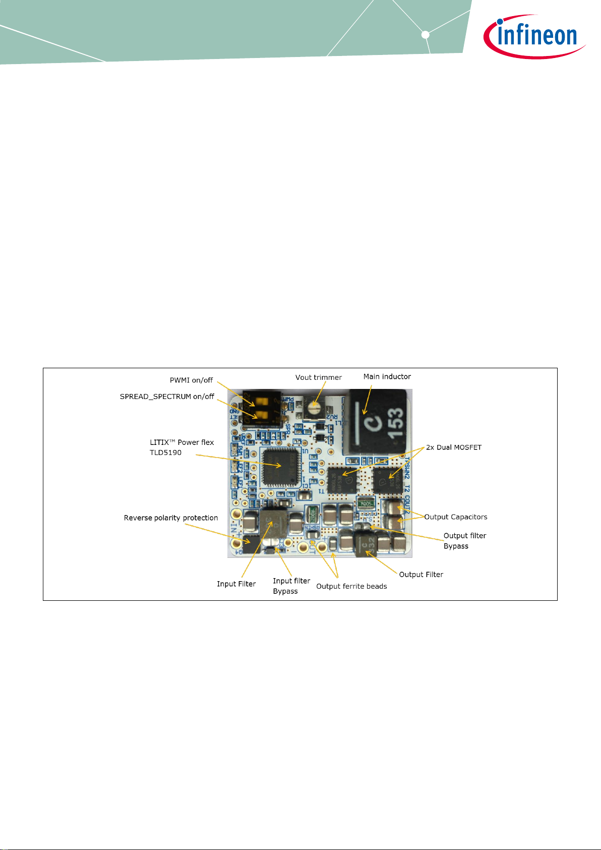
The TLD5190 VOLT DEMO is an evaluation platform for the TLD5190 set as compact voltage regulator.
Figure 1 TLD5190 VOLT DEMO evaluation board
Intended audience
Hardware engineers, system architects
Page 2

User Manual 2 of 12 Rev.1.00
2020-06-05
TLD5190 VOLT DEMO evaluation board
User Manual
Table of contents
1 Table of contents
About this document ......................................................................................................................... 1
1 Table of contents ...................................................................................................................... 2
2 Description .............................................................................................................................. 3
3 Quick start procedure ............................................................................................................... 4
4 Operating range and power derating ......................................................................................... 6
5 Electrical characteristics ........................................................................................................... 7
6 PCB - component placement ..................................................................................................... 8
7 Schematic ................................................................................................................................ 9
8 BOM .......................................................................................................................................10
Revision history ...............................................................................................................................11
Page 3
User Manual 3 of 12 Rev.1.00
2020-06-05
TLD5190 VOLT DEMO evaluation board
User Manual
Description
2 Description
The H-Bridge architecture is among the most efficient buck-boost topologies for high current applications. The
TLD5190 can be configured as voltage regulator or LED driver.
The TLD5190 VOLT DEMO is an evaluation platform for the TLD5190 as voltage regulator. The PCB is extremely
compact and can fit in to small applications enclosures for fast prototyping.
Note: The board has been designed as voltage pre-regulator for rear lighting applications, so it will
startup correctly only with output current > 100 mA. In case of startup with no load the soft-start
capacitor has to be dimensioned accordingly with the application conditions (input and output
voltage).
The soft start enables DCM (Discontinuous Conduction Mode), this may prevent exact regulation at startup with
no load. In case of startup without load the output voltage may rise above the target and the Comp capacitor to
be discharged. After the soft start expires, the TLD5190 applies CCM, and the output voltage would be discharged
producing a short circuit detection.
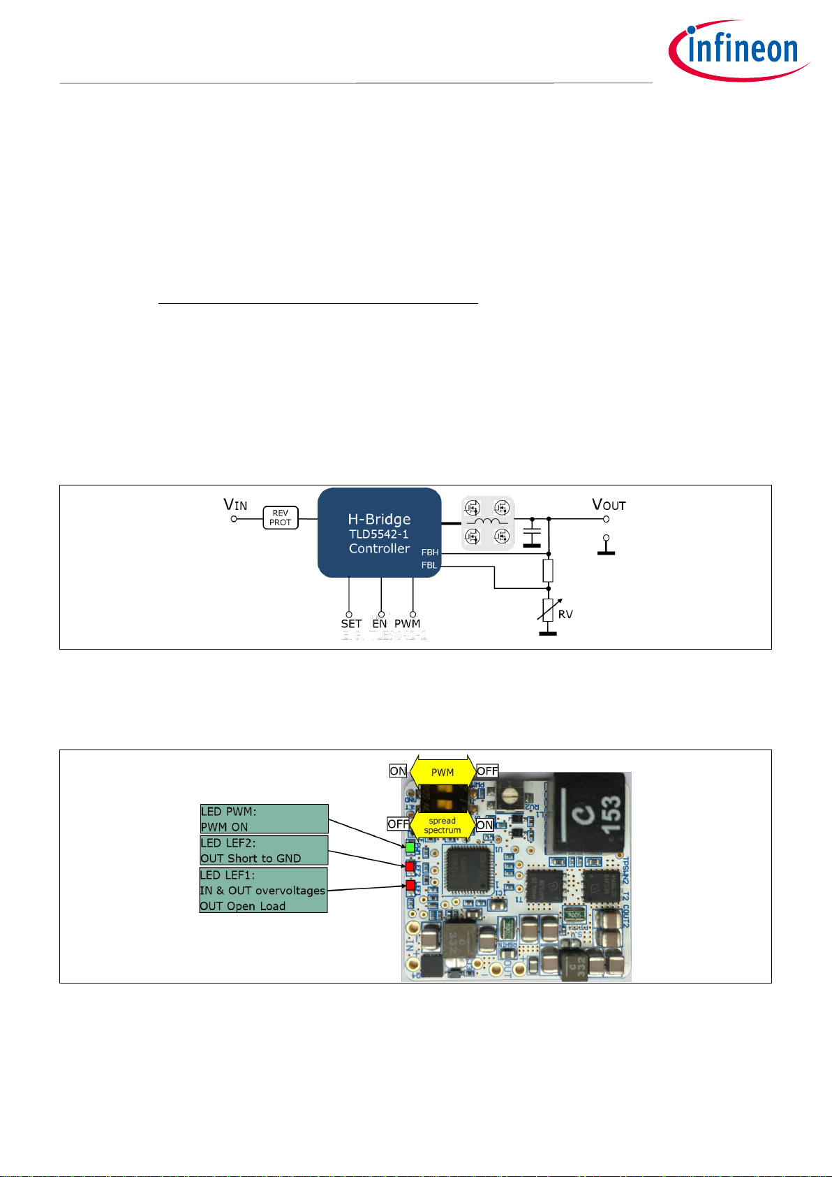
Figure 2 TLD5190 as voltage regulator
On the board, in addition there are 3 LEDs to indicate PWMI and error flags status, and 2 switches to activate
spread spectrum and PWMI.
Figure 3 TLD5190 VOLT DEMO LEDs signals
Page 4
User Manual 4 of 12 Rev.1.00
2020-06-05
TLD5190 VOLT DEMO evaluation board
User Manual
Quick start procedure
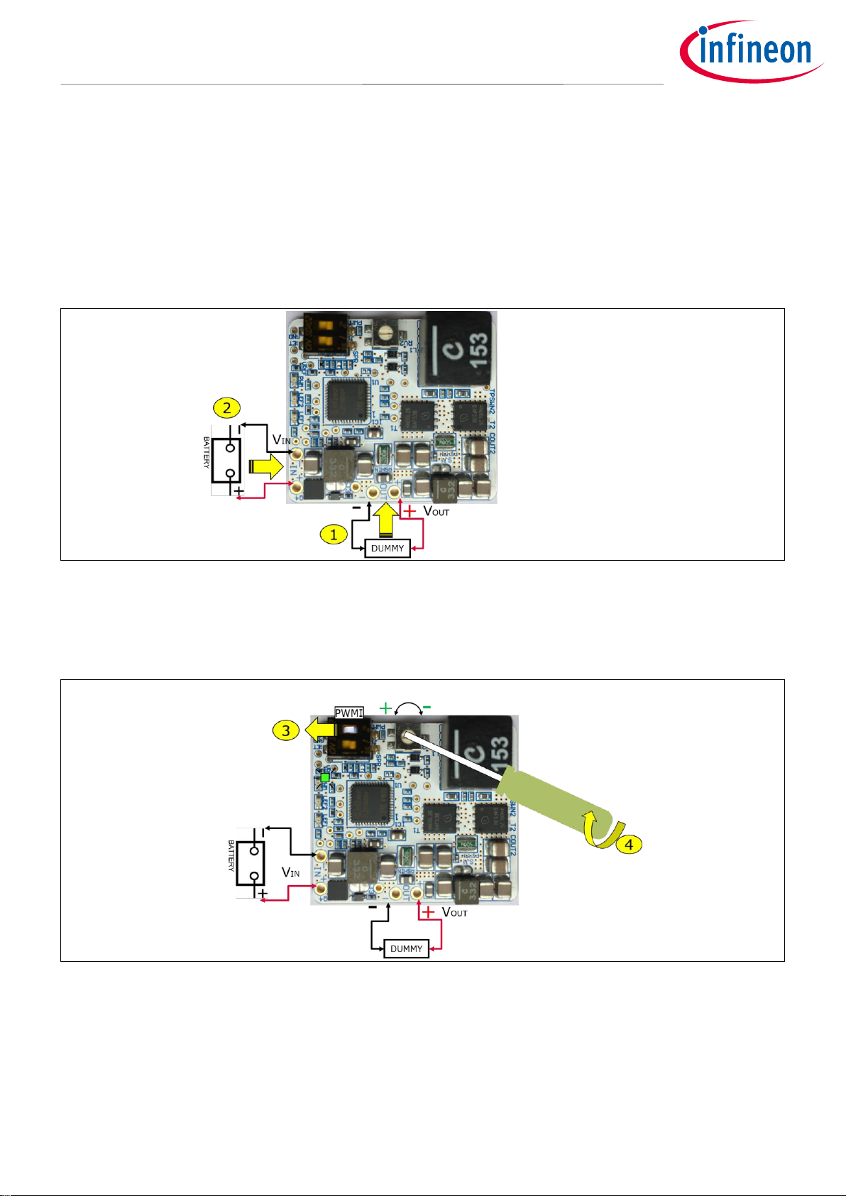
3 Quick start procedure
Below, step by step procedures are laid out for setup and running the TLD5190 VOLT DEMO.
1. Connect a dummy load at the OUT terminals which could withstand the Max V
OUT
a. Example: 10W 47 Ω resistor
2. Connect the power supply at the IN terminals
Figure 4 Connect the load and the power supply
3. Set J1-PWMI DIP switch to ON → the green PWMI LED should light up
4. Set the output voltage to the desired value by rotating RV2
Figure 5 Set PWMI to ON and trim V
OUT
to the desired value
5. Now that V
OUT
has been trimmed to the right value, connect the real load at the OUT terminals
Page 5

User Manual 5 of 12 Rev.1.00
2020-06-05
TLD5190 VOLT DEMO evaluation board
User Manual
Quick start procedure
Figure 6 Connect the real load
Page 6

User Manual 6 of 12 Rev.1.00
2020-06-05
TLD5190 VOLT DEMO evaluation board
User Manual
Operating range and power derating
4 Operating range and power derating
The TLD5190 VOLT DEMO has very high efficiency, so it can deliver up to 40 W at the output without a heat sink
at TA = 25°C, VIN = 12 V I
OUT
< 3 A (see Figure 7 for power-derating curve).
Note: The module does not implement thermal protection, so ensure proper cooling when output power
exceeds the power-derating curve. The heat sink has to be positioned below the switching
MOSFETs.
P
out
[W]
6
9
29 V
IN
[V]
40
20
12
30
TA=25°C
Figure 7 Output power derating curve (T
A
= 25°C, I
OUT
< 3 A)
Page 7

User Manual 7 of 12 Rev.1.00
2020-06-05
TLD5190 VOLT DEMO evaluation board
User Manual
Electrical characteristics
5 Electrical characteristics
Table 1 TLD5190 VOLT DEMO schematic version V3.1 – Electrical characteristics
Figure 8 TLD5190 VOLT DEMO Efficiency
87
89
91
93
95
97
99
0 5 10 15 20 25
Efficiency %
P
OUT
(W)
TLD5190 MiniVDemo Efficiency V
IN
= 12 V, V
OUT
= 9 V. I
OUT
: from 0.4 A to 2.1 A
with filters
without filters
Parameter
Symbol
Value
Unit
Note/Test Condition
Min.
Typ.
Max.
Input voltage
VIN
5 – 29 V –
Output voltage
V
OUT
3 – 21
V
RV2 trimmer could set V
OUT
as low as 1.5 V , but
short to GND would be detected
Output current
I
OUT
0 – 3 A –
Input current limit
I
IN_MAX
– 7 –
A
–
Output power
P
OUT
– 40 – W
V
IN
12 V to 28 V, I
OUT
< 3 A, TA = 25°C
see Figure 7 for power derating curve
Switching
frequency
Switching
frequency
–
290 – kHz
Spread spectrum deviation is present
System efficiency
Eff – 94 – %
–
Page 8

User Manual 8 of 12 Rev.1.00
2020-06-05
TLD5190 VOLT DEMO evaluation board
User Manual
PCB - component placement
6 PCB - component placement
Figure 9 PCB dimensions and component placement - top view
Page 9

User Manual 9 of 12 Rev.1.00
2020-06-05
TLD5190 VOLT DEMO evaluation board
User Manual
Schematic
7 Schematic
Figure 10 Schematic
Page 10

User Manual 10 of 12 Rev.1.00
2020-06-05
TLD5190 VOLT DEMO evaluation board
User Manual
About this document
8 BoM
Table 2 BoM TLD5190 microVBoard
BoM: TLD5190 - microVBoard R2
Configuration: Voltage mode
Designator
Comment
Footprint
C6
15nF 16V X7R
C0402
C9,C21,CIN1,CIN2,COUT1,COUT2,COUT3,COUT4,COUT5
10uF 50V 1210
C1210
C50
100n 0402
C0402
C55
1uF 50V X7R 0603
C0805
C66
nm
C0402
C67
nm
C0402
C69
10n 50V 0402
C0402
CBS1,CBS2,CIN3,CREF
100nF 50V
C0402
CIN_FILT
220nF 6.3V 0402
C0402
CIVCC
10uF 6.3V 0805
C0805
CSNUB2,CSNUB3
680pF
C0402
CSOFTSTART
22nF 16V
C0402
DBS1,DBS2
NXP_BAT46WJ
SOD323F
DZ3
ZENER 10V
SOD323
FB1, FB2
IND 220R/100MHz
IND SMD 0805
J1
A6S-2104-H
DIP SW 2 SMD SDA02H0SB
L1
XAL1010-153
IND SMD XAL1010+XAL8080
L3
XAL4030-332
IND SMD XAL4030
LEF1,LEF2
RED LED
LED 0603 RED
L_IN
XAL5030-332
IND SMD XAL5030
PWM
GREEN LED
LED 0603 GREEN
Q4
BSZ08P03NS3
PG-TSDSON-8 SGD
R26
10k 1% 0402
R0402
R34,R35,R45
1k5
R0402
R58,R59,R61
10kΩ1%
R0402
R60
1k5
R0402
R111
50Ω
R0402
Rcomp
1k 1% 0402
R0402
REN3
10kΩ 0402
R0402
RFH
150
R0402
RFL
1k5
R0402
RFREQ
39kΩ 0402
R0402
RG1,RG2,RG3,RG4
10 Ω
R0402
RSHIN
7mΩ 0612
R0612
RSHSW
5mΩ 0612
R0612
RSNUB2,RSNUB3
5.1Ω
R0603
RUV1
14.3k 1% 0402
R0402
RUV2
6.2k 1% 0402
R0402
RUV3
1k5 1% 0402
R0402
RV2
20k TRIM
TRIMMER SMD 23B
RVFBH
33k 1%
R0402
RVFBH2
14.3k 1%
R0402
RVFBL
1k5
R0402
SJ1,SJ2
SOLDER JUMP
T1,T2
IFX_IPG20N06S4L-26
PG-TDSON-8-4
U1
TLD5190QV
VQFN48 7X7 P05
Page 11

User Manual 11 of 12 Rev.1.00
2020-06-05
TLD5190 VOLT DEMO evaluation board
User Manual
Revision history
Revision history
Document
version
Date of release
Description of changes
Rev. 1.00
2020-06-05
Initial User Manual
Page 12

Published by
Infineon Technologies AG
81726 München, Germany
© 2020 Infineon Technologies AG.
All Rights Reserved.
Do you have a question about this
document?
Email: erratum@infineon.com
Document reference
IMPORTANT NOTICE
The information given in this document shall in no
event be regarded as a guarantee of conditions or
characteristics (“Beschaffenheitsgarantie”) .
With respect to any examples, hints or any typical
values stated herein and/or any information
regarding the application of the product, Infineon
Technologies hereby disclaims any and all
warranties and liabilities of any kind, including
without limitation warranties of non-infringement of
intellectual property rights of any third party.
In addition, any information given in this document
is subject to customer’s compliance with its
obligations stated in this document and any
applicable legal requirements, norms and standards
concerning customer’s products and any use of the
product of Infineon Technologies in customer’s
applications.
The data contained in this document is exclusively
intended for technically trained staff. It is the
responsibility of customer’s technical departments
to evaluate the suitability of the product for the
intended application and the completeness of the
product information given in this document with
respect to such application.
For further information on the product, technology,
delivery terms and conditions and prices please
contact your nearest Infineon Technologies office
(www.infineon.com).
WARNINGS
Due to technical requirements products may contain
dangerous substances. For information on the types
in question please contact your nearest Infineon
Technologies office.
Except as otherwise explicitly approved by Infineon
Technologies in a written document signed by
authorized representatives of Infineon
Technologies, Infineon Technologies’ products may
not be used in any applications where a failure of the
product or any consequences of the use thereof can
reasonably be expected to result in personal injury.
Edition 2020-06-05
UM TLD5190 VOLT DEMO
Trademarks
All referenced product or service names and trademarks are the property of their respective owners.
 Loading...