

Page 1
Marketing Information
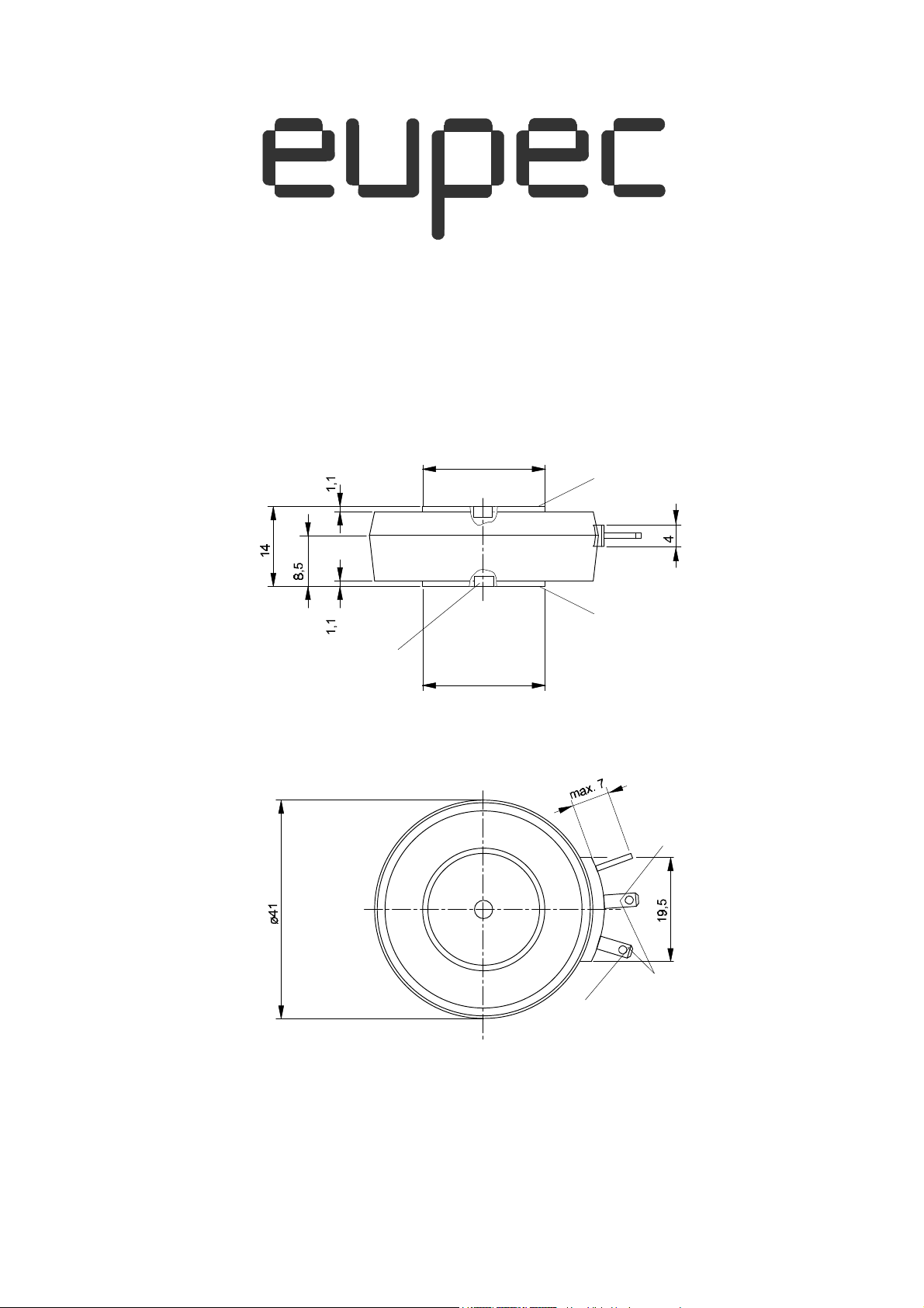
T 178 N
European PowerSemiconductor and
Electronics Company
ø3,5 x 2 deep
on both sides
ø23
C
A
ø23
HK
plug
G
2,8 x 0,8
VWK Aug. 1996
Page 2

T 178 N
Elektrische Eigenschaften
Electrical properties
Höchstzulässige Werte
Maximum rated values
Periodische Vorwärts- und Rückwärts-
600 800 1000 1200
600 800 1000 1200
700 900 1100 1300
Charakteristische Werte
Characteristic values
Thermische Eigenschaften
Thermal properties
Mechanische Eigenschaften
Mechanical properties
Spitzensperrspannung
repetitive peak forward off-state and
reverse voltages
tvj = -40°C...t
vj max
V
DRM
, V
RRM
1400 1600 1800
V
Vorwärts-Stoßspitzensperrspannung non-repetitive peak forward off-state
voltage
Rückwärts-Stoßspitzensperrspannung non-repetitive peak reverse voltage tvj = +25°C...t
tvj = -40°C...t
vj max
vj max
Durchlaßstrom-Grenzeffektivwert RMS on-state current I
Dauergrenzstrom average on-state current tc = 85°C I
tc = 81°C 190 A
Stoßstrom-Grenzwert surge current tvj = 25°C, tp = 10 ms I
tvj = t
, tp = 10 ms 2600 A
vj max
Grenzlastintegral
I2 t-value
Kritische Stromsteilheit critical rate of rise of on-state current
tvj = 25°C, tp = 10 ms
tvj = t
, tp = 10 ms 34000
vj max
vD ≤ 67%, v
, f = 50 Hz
DRM
vL=10 V, iGM= 0,75 A, diG/dt =0,75 A/µs
Kritische Spannungssteilheit critical rate of rise of off-state voltage tvj = t
, vD = 67% V
vj max
DRM
Durchlaßspannung on-state voltage tvj = t
Schleusenspannung threshold voltage tvj = t
Ersatzwiderstand slope resistance tvj = t
, iT = 600 A v
vj max
vj max
vj max
Zündstrom gate trigger current tvj = 25 °C, vD = 6 V I
Zündspannung gate trigger voltage tvj = 25 °C, vD = 6 V V
Nicht zündender Steuerstrom gate non-trigger current tvj = t
Nicht zündende Steuerspannung gate non-trigger voltage tvj = t
Haltestrom holding current
Einraststrom latching current
, vD = 6 V I
vj max
, vD = 0,5 V
vj max
DRM
tvj = 25 °C, vD = 6 V, RA = 5 Ω
tvj = 25 °C,vD = 6 V, RGK ≥ 10 Ω
iGM =0,75 A, diG /dt =0,75 A/µs, tg = 20 µs
Vorwärts- und Rückwärts-Sperrstrom forward off-state and reverse currents tvj = t
vj max, vD
= V
DRM
, vR = V
RRM
Zündverzug gate controlled delay time tvj=25°C, iGM =0,75 A,diG/dt =0,75 A/µs t
Freiwerdezeit circuit commutated turn-off time siehe Techn.Erl./see Techn. Inf. t
V
DSM
V
RSM
TRMSM
TAVM
TSM
I2 t
(diT/dt)
(dv/dt)
T
V
T(TO)
r
T
GT
GT
GD
V
GD
I
H
I
L
iD, i
R
gd
q
= V
= V
DRM
RRM
1400 1600 1800
1500 1700 1900
V
V
300 A
178 A
3000 A
45000
A2s
A2s
cr
cr
150 A/µs
1000 V/µs
max. 1,9 V
0,92 V
1,5
mΩ
max. 150 mA
max. 2 V
max. 10 mA
max. 0,25 V
max. 200 mA
max. 800 mA
max. 25 mA
max. 4,5 µs
typ. 180 µs
Innerer Wärmewiderstand für beidseitige
thermal resistance, junction to case for
Θ =180° el, sin
R
thJC
max. 0,141 °C/W
DC max. 0,133 °C/W
für anodenseitige Kühlung for anode-sided cooling
Θ =180° el, sin
R
thJC(A)
max. 0,224 °C/W
DC max. 0,216 °C/W
für kathodenseitige Kühlung for cathode-sided cooling
Θ =180° el, sin
R
thJC(K)
max. 0,344 °C/W
DC max. 0,336 °C/W
Übergangs-Wärmewiderstand thermal resistance, case to heatsink beidseitig/two-sided max. 0,015 °C/W
einseitig/one-sided max. 0,030 °C/W
Höchstzul.Sperrschichttemperatur max. junction temperature t
Betriebstemperatur operating temperature t
Lagertemperatur storage temperature t
vj max
c op
stg
125 °C
-40...+125 °C
-40...+140 °C
Si-Elemente mit Druckkontakt Si-pellet with pressure contact
Anpreßkraft clamping force F 2,5...5 kN
Gewicht weight G typ. 70 g
Kriechstrecke creepage distance 17 mm
Feuchteklasse humidity classification DIN 40040 C
Schwingfestigkeit vibration resistance f = 50 Hz 50 m/s²
Maßbild, anliegend outlines, attached DIN 41814-151A4
Page 3
T 178 N
i
[A]
T
1500
tvj = +25°C
1000
500
0
T 178 N / 1
a
b
1 2 3 4
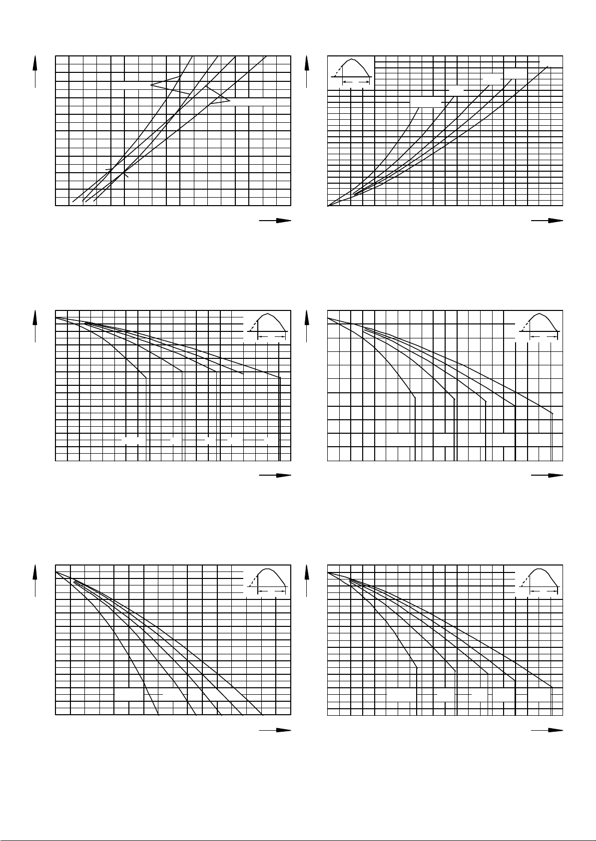
Bild / Fig. 1
Durchlaßkennlin ien / On-state characteristics iT = f(vT)
a -Typis che Kennlin ien / typical characteris tic s
b -Grenzkennl inien / limiting c haracteristic s
120
100
t
C
[°C]
80
300
90°
tvj = +125°C
P
[W]
TAV
250
0 Θ
60°
Θ = 3 0°
200
150
100
50
0
vT [V]
0
T 178 N / 2
50 100 150 200
Bild / Fig. 2
Durchlaßverlustle istung / O n-state power loss P
Parameter: Stromflußwink el / Current conduction angle θ
TAV
= f(I
120
0 Θ 0 Θ
100
t
C
[°C]
80
I
TAV
TAV
180°
120°
[A]
)
60
40
20
0
T 178 N / 3
Θ = 3 0° 60° 90° 120° 180°
50 100 150 200
I
Bild / Fig. 3
Höchstzuläs sige Gehä use tempe ratur / Max. allowable c ase temperature
tC = f(I
Bei dseitege Kühlung / Two-sided cooling
TAVM
)
Parameter: Stromflu ßwink el / Current conduction angle θ
120
100
t
A
[°C]
80
60
40
Θ = 30° 60° 9 0° 120° 180°
TAVM
[A]
60
40
20
0
T 178 N / 4
Θ = 30° 60° 90° 120° 180°
50 100 150 200
I
[A]
TAVM
Bild / Fig. 4
Höchstz ulässi ge Gehäusetemperatur / Max. all owable case temperature
tC = f(I
Anodenseitige Kühlu ng / Anode-sided cooling
TAVM
)
Parameter: Stromflußwink el / Current conduction angle θ
120
Θ
0
100
t
A
[°C]
Θ
0
80
60
40
Θ = 3 0° 60° 90° 120° 180°
20
0
T 178 N / 5
50 100 150
I
[A]
TAVM
Bild / Fig. 5
Höchstzuläs sige Kühlmitteltemperatur / Max. allowable c ooling mediu m
temperatur tA = f(I
Luftselbstk ühlung / Natural ai r-cooling
TAVM
)
Kühlkö rper / Heatsi nk: K0. 36S
Parameter: Stromflu ßwink el / Current conduction angle θ
20
0
T 178 N / 6
50 100 150 200
I
[A]
TAVM
Bild / Fig. 6
Höchstz ulässi ge Kühlmitte ltempe ratur / Max. allowable cooling medi um
temperatur tA = f(I
Verstärkte Luftkühlu ng / Forced air cool ing
TAVM
)
Kühlkörper / Heatsink: K0.12F, VL = 50 l/s
Parameter: Stromflußwink el / Current conduction angle θ
Page 4

T 178 N
400
0 Θ
P
[W]
TAV
300
Θ = 30°
60°
90°
120°
200
100
0
0 200
T 178 N / 7
100
Bild / Fig. 7
Durchlaßverlustl eistun g / On-state power los s P
Parameter: Stromflu ßwink el / Current conduction angle θ
120
100
t
C
[°C]
80
180°
TAV
= f(I
I
TAV
TAV
[A]
)
0 Θ
DC
300
120
100
t
C
[°C]
80
60
40
20
0
T 178 N / 8
Θ = 3 0°
60°
90°
120° 180° DC
100 200 300
Bild / Fig. 8
Höchstz ulässi ge Gehäusetemperatur / Max. all owable case temperature
tC = f(I
Beid sei tige Kühlung / Two-sided coo li ng
TAVM
)
Parameter: Stromflußwink el / Current conduction angle θ
120
100
t
A
[°C]
80
I
TAVM
0 Θ
[A]
0 Θ
60
40
20
0 200
T 178 N / 9
Θ = 3 0° 60° 90° 120° 180° D C
100
I
Bild / Fig. 9
Höchstzuläs sige Gehä use tempe ratur / Max. allowable c ase temperature
tC = f(I
Anodenseitige Kühlung / Anode-sided c ooling
TAVM
)
Parameter: Stromflu ßwink el / Current conduction angle θ
120
100
t
A
[°C]
80
60
40
20
0
T 178 N / 11
Θ = 30° 60° 90° 120° 180° DC
100 200 300
I
Bild / Fig. 11
Höchstzuläs sige Kühlmitteltemperatur / Max. allowable c ooling m ediu m
temperatur tA = f(I
Verstärkte Luftkühlk ühlung / forced air cool ing
TAVM
)
Kühlkö rper / Heatsi nk: K0. 12F, VL = 50 l/s
Parameter: Stromflu ßwink el / Current conduction angle θ
TAVM
TAVM
[A]
[A]
0 Θ
300
60
40
20
0
T 178 N / 10
Θ = 30° 60° 90° 120° 180° D C
50 100 150 200
I
[A]
TAVM
Bild / Fig. 10
Höchstz ulässig e Kühlmitteltem peratur / Max. all owa ble co oling m edium
temperatur tA = f(I
Luftselbstk ühlung / Natural air-cooling
TAVM
)
Kühlkörper / Heatsink: K0.36S
Parameter: Stromflußwink el / Current conduction angle θ
3
I
TAV(vor) =
2
0
25A
I
T(0V)
[kA]
50A
75A
1
100A
0,6
0,4
0,3
10 20 40 100 20 04 00 1 2 4 10 20 40 1 2 4 10 20 4 01h
T 178 N / 12
ms
s
Bild / Fig. 12
Überstrom / Overload on-state current I
Luftselbstk ühlung / Natural air-cooling tA = 45°C
T(OV)
= f(t)
Kühlkörper / Heatsink: K0.36S
Parameter: Vorlaststrom / Pre-load current I
TAV(vor)
min
K 0,3 5
tA=45°
t
Page 5

T 178N
3
I
TAV(vor)=
2
40A
1
60
120A
160A
0
A
I
T(0V)
[kA]
0,6
0,4
0,3
10 20 40 100 2 00 400 1 2 4 10 20 401 2 4 10 20 401h
T 178 N / 13
ms s min
Bild / Fig. 13
Überstrom / Overload on-state current I
Verstärkte Luftkühlu ng / Forced air-cooli ng, tA= 35 °C
T(OV )
= f(t)
Kühlkö rper / Heatsi nk: K0. 12F, VL = 50 l/s
Parameter: Vorlaststrom / Pre-load current I
600
500
1min
I
TIN T
[A]
I
TAV
(vor)=0
4min
10
min
300
40min
2h
200
100
0,1 0,2 0,4 1 2 4 10 20 40100 200 400 500
T 178 N / 15
0,4s1s4s20s
ED [%]
SD =
0,1 s
TAV(vor)
I
TAV(vor)
100A 120A
SD
I
TAV(vor) =
100 300 600
I
[A]
TI NT
Bild / Fig. 15
Höchstzuläs siger Durchlaßstrom bei Aus setzbetrieb / Max. al lowable
on-stat e current at intermittent operation I
Verstärkte Luftkühlu ng / Forced air-cooli ng, tA= 35 °C
TI NT
= f(ED)
Kühlkö rper / Heatsi nk: K0. 12F, VL = 50 l/s
Parameter: Spi eldauer / Cycle durati on SD
Vorlaststrom / Pre-load cu rrent I
TAV(vor)
20
10
8
6
v
G
4
[V]
2
1,0
0,8
0,6
0,4
0,2
0,1
1
10
T 178 N / 17
2 4 6
10
2
2 4 6
10
3
2 4 6
iG [mA]
Bild / Fig. 17
Steuercharakteristik mit Zündbereic hen / Gate characterist ic with triggin g
areas vG = f(iG), VD = 6 V
Parameter: a b c
––––––––––––– –––––––––––––––––––– –––––––––––––––––––––––––
Steuerimpuls dauer / trigge r puls duratio n tg [ms] 10 1 0,5
––––––––––––– –––––––––––––––––––– –––––––––––––––––––––––––
Höchstzuläs sige Spit z ensteuerverlus tl eistung /
Max . rated peak gate power di ssi pation [W] 20 40 60
––––––––––––– –––––––––––––––––––– –––––––––––––––––––––––––
t
80A
1
K 0,1 2F
vL=50 l/s
tA=35°C
40A
I
2
TINT
3
600
500
I
TIN T
[A]
I
TAV
(vor)=0
300
200
100
4s20s
1s
0,4s
1min
4min
10
min
40min
2h
0,1 0,2 0,4 1 2 4 10 20 40100 200 400 500
T 178 N / 14
ED [%]
SD=
0,1s
100 300 600
TAV(vor)=
100A 80A
I
TAV(vor)
I
TI NT
SD
[A]
I
030A60AI
TINT
Bild / Fig. 14
Höchstz ulässi ger Durchlaßstrom bei Aus setzbetrieb / Max. allo wabl e
on-state current at intermittent operation I
Luftselbstk ühlung / Natural air-cooling, tA = 45°C
TIN T
= f(ED)
Kühlkörper / Heatsink: K0.36S
Parameter: Spie ldauer / Cycl e duration SD
Vorlaststrom / Pre-load current I
0
a
2
I
T(0V)M
[kA]
K0,36S tA=45°C
b
1
0
10 20 40 60 100 200 400 600 1 2 4 6 10
T 178 N / 16
K0,36S tA=45°C
ms s
TAV(vo r)
K0,12F; vL=50 l/s
tA=35°C
K0,12F; vL=50 l/s
tA=35°C
t
Bild / Fig. 16
Grenzs trom / Max. overl oad on-state current I
Luftselbstk ühlung / Natural air-cooling , tA = 45°C
Kühlkörper / Heatsink: K0.36S
Verstärkte Luftkühlu ng / Forced air-cooli ng, tA= 35°C
Kühlkörper / Heatsink: K0.12F
Bela stung aus / Surge current occ urs:
a - Leerlauf / No-load co ndit ions
b - Betrieb mit Dauergrenzstrom / During operation at max. average on-state
current I
3
10
TAVM
= f(t), vRM = 0,8 V
T(OV)M
RRM
4
t
2
gd
10
[µs]
40
20
10
6
4
2
1
0,4
0,2
0,1
4
10
10 20 40 60 100 200 400 1 2 4 6 10 20 40 60 100
T 178 N / 18
mA A
a
b
tvj=25°C
i
GM
Bild / Fig. 18
Zündverzug / Gate controlled dela y time tgd = f(iGM)
tvj = 25 °C, diG/dt = iGM/1µs
a - Maximale r Verlauf / Limiting c haracteristic
b - Typischer Verla uf / Typic al characteris tic
Page 6

4
10
8
6
4
Q
r
[µAs ]
2
3
10
8
6
4
2
2
10
0 2 3 4 5 6 7 8101 2 3 4 5 6 7 8102
10
T 178 N / 19
iTM=
200A
100A
-di/dt [A/µs ]
50A
20A
Bild / Fig. 19
Sperrverzögerungsladung / Recovered charg e Qr = f(di/dt)
tvj = t
Parameter: Durchlaßstrom / On-state current i
vj max
, vR = 0,5 V
, vRM = 0,8 V
RRM
RRM
TM
500A
T 178 N
0,32
0,28
0 Θ
Z
(th )JC
[°C/W]
0,20
0,16
0,12
Θ=
30°
0,08
60°
90°
0,04
120°
180°
0
10 20 40 60 100 200 400 1 2 4 6 10 20 40 60 100
T 178 N / 20
Bi ld / Fig. 20
Transienter innerer Wärmewiderstand / Transient thermal imped ance
Z
= f(t)
thJ C
Parameter: Stromf lußwin kel / current conduc tion angle θ
ms
Anodenseitige Kühlung / Anode-sided c ooli ng
Beids eitige Kühlu ng / Two-sided c ooling
s
t
0,3
0 Θ
Z
(th )J C
[°C/W]
0,2
Θ=
0,1
0
1 2 4 10 20 40 100 200 400 1 2 4
T 178 N / 21
30°
60°
90°
120°
180°
DC
Bild / Fig. 21
Transienter inne rer Wä rmewiderstand / Transient thermal impedance
Z
= f(t)
thJ C
Anodenseitige Kühlung / Anode-side d c ooli ng
Beids eitige Kühlu ng / Two-sided c ooling
Parameter: Stromf lußwi nkel / current condu ction ang le θ
Analy tische Ele me nte de s trans ienten Wärmewiderstandes Z
Analy tical el ements of transient thermal impe dance Z
t hJC
pro Zweig für DC
thJ C
per arm for DC
Beids eitig / Two-sided
Pos. n 1 2 3 4 5 6 7
R
τ
thn
[s]
n
[°C/W]
0,0069 4 0 ,0131 0,023 0,0335 0 ,0552 0,0011
0,000727 0,00909 0,0281 0,134 0 ,52 9 2,27
Anodenseiti g / Anode-sid ed
Pos. n 1 2 3 4 5 6 7
R
τ
thn
[s]
n
[°C/W]
0,0075 5 0 ,0246 0,0215 0,0799 0,0683 0,0141
0,000812 0,0132 0,064 0,412 1,88 10,8
Kathoden se itig / Cathode-sided
Pos. n 1 2 3 4 5 6 7
10
sms
t
10020 40
R
[°C/W]
thn
τ
[s]
n
0,0078 4 0 ,0277 0,022 0,0947 0,115 0,0691
0,000855 0,0143 0,123 0,473 2,17 10
Analy tische Funktion / Analytical function:
n
Z
t hJC
max
= R
Σ
n=1
(1-e )
thn
t
-
τ
n
Page 7

Nutzungsbedingungen
Die in diesem Produktdatenblatt enthaltenen Daten sind ausschließlich für technisch geschultes Fachpersonal bestimmt. Die
Beurteilung der Geeignetheit dieses Produktes für die von Ihnen anvisierte Anwendung sowie die Beurteilung der Vollständigkeit der
bereitgestellten Produktdaten für diese Anwendung obliegt Ihnen bzw. Ihren technischen Abteilungen.
In diesem Produktdatenblatt werden diejenigen Merkmale beschrieben, für die wir eine liefervertragliche Gewährleistung
übernehmen. Eine solche Gewährleistung richtet sich ausschließlich nach Maßgabe der im jeweiligen Liefervertrag enthaltenen
Bestimmungen. Garantien jeglicher Art werden für das Produkt und dessen Eigenschaften keinesfalls übernommen.
Sollten Sie von uns Produktinformationen benötigen, die über den Inhalt dieses Produktdatenblatts hinausgehen und
insbesondere eine spezifische Verwendung und den Einsatz dieses Produktes betreffen, setzen Sie sich bitte mit dem für Sie
zuständigen Vertriebsbüro in Verbindung (siehe www.eupec.com, Vertrieb&Kontakt). Für Interessenten halten wir Application
Notes bereit.
Aufgrund der technischen Anforderungen könnte unser Produkt gesundheitsgefährdende Substanzen enthalten. Bei Rückfragen
zu den in diesem Produkt jeweils enthaltenen Substanzen setzen Sie sich bitte ebenfalls mit dem für Sie zuständigen Vertriebsbüro
in Verbindung.
Sollten Sie beabsichtigen, das Produkt in gesundheits- oder lebensgefährdenden oder lebenserhaltenden Anwendungsbereichen
einzusetzen, bitten wir um Mitteilung. Wir weisen darauf hin, dass wir für diese Fälle
- die gemeinsame Durchführung eines Risiko- und Qualitätsassessments;
- den Abschluss von speziellen Qualitätssicherungsvereinbarungen;
- die gemeinsame Einführung von Maßnahmen zu einer laufenden Produktbeobachtung dringend empfehlen und gegebenenfalls die
Belieferung von der Umsetzung solcher Maßnahmen abhängig machen.
Soweit erforderlich, bitten wir Sie, entsprechende Hinweise an Ihre Kunden zu geben.
Inhaltliche Änderungen dieses Produktdatenblatts bleiben vorbehalten.
Terms & Conditions of usage
The data contained in this product data sheet is exclusively intended for technically trained staff. You and your technical
departments will have to evaluate the suitability of the product for the intended application and the completeness of the product
data with respect to such application.
This product data sheet is describing the characteristics of this product for which a warranty is granted. Any such warranty is
granted exclusively pursuant the terms and conditions of the supply agreement. There will be no guarantee of any kind for the
product and its characteristics.
Should you require product information in excess of the data given in this product data sheet or which concerns the specific
application of our product, please contact the sales office, which is responsible for you (see www.eupec.com, sales&contact). For
those that are specifically interested we may provide application notes.
Due to technical requirements our product may contain dangerous substances. For information on the types in question please
contact the sales office, which is responsible for you.
Should you intend to use the Product in health or live endangering or life support applications, please notify. Please note, that for
any such applications we urgently recommend
- to perform joint Risk and Quality Assessments;
- the conclusion of Quality Agreements;
- to establish joint measures of an ongoing product survey,
and that we may make delivery depended on the realization
of any such measures.
If and to the extent necessary, please forward equivalent notices to your customers.
Changes of this product data sheet are reserved.
 Loading...