

N
A
Datenblatt / Data sheet
Netz-Thyristor
Phase Control Thyristor
Elektrische Eigenschaften / Electrical properties
Höchstzulässige Werte / Maximum rated values
Periodische Vorwärts- und Rückwärts-Spitzensperrspannung
enndaten
repetitive peak forward off-state and reverse voltages
Vorwärts-Stossspitzensperrspannung
non-repetitive peak forward off-state voltage
Rückwärts-Stossspitzensperrspannung
non-repetitive peak reverse voltage
Durchlassstrom-Grenzeffektivwert
maximum RMS on-state current
Dauergrenzstrom
average on-state current
Dauergrenzstrom
average on-state current
Durchlaßstrom-Effektivwert
RMS on-state current
Stossstrom-Grenzwert
surge current
Grenzlastintegral
I²t-value
Kritische Stromsteilheit
critical rate of rise of on-state current
Kritische Spannungssteilheit
critical rate of rise of off-state voltage
Elektrische Eigenschaften
T1220N
= -40°C... T
T
vj
Tvj = -40°C... T
Tvj = +25°C... T
V
vj max
V
vj max
V
vj max
I
TC = 85 °C
DRM,VRRM
DSM
RSM
TRMSM
I
TAVM
TC = 55 °C, θ = 180°sin, tP = 10 ms I
I
T
= 25 °C °C, tP = 10 ms
vj
= T
T
vj
, tP = 10 ms
vj max
Tvj = 25 °C, tP = 10 ms
T
= T
vj
, tP = 10 ms
vj max
DIN IEC 60747-6
f = 50 Hz, i
Tvj = T
5.Kennbuchstabe / 5
= 1 A, diG/dt = 1 A/µs
GM
, vD = 0,67 V
vj max
DRM
th
letter F
TAVM
TRMS
I
TSM
I²t
(di
(dv
/dt)cr
T
D
/dt)cr
2000
2200
2000
2200
2100
2300
2400
2600
2800
2400
2600
2800
2500
2700
2900
2625 A
1220 A
1740 A
2740 A
25000
22500
3125
2531
150 A/µs
1000 V/µs
V
V
V
V
V
V
V
V
V
A
A
10³ A²s
10³ A²s
Charakteristische Werte / Characteristic values
Durchlassspannung
on-state voltage
Schleusenspannung
threshold voltage
Ersatzwiderstand
slope resistance
Durchlasskennlinie 300 A ≤ iT ≤ 6100 A
on-state characteristic
TTT
Zündstrom
gate trigger current
Zündspannung
gate trigger voltage
Nicht zündender Steuerstrom
gate non-trigger current
Nicht zündende Steuerspannung
gate non-trigger voltage
Haltestrom
holding current
Einraststrom
latching current
Vorwärts- und Rückwärts-Sperrstrom
forward off-state and reverse current
Zündverzug
gate controlled delay time
Tvj = T
T
= T
vj
Tvj = T
Tvj = T
= T
T
vj
, iT = 3,5 kA
vj max
, iT = 1,0 kA
vj max
V
vj max
r
vj max
A=
vj max
v
T
(TO)
T
max.
max.
1,0 V
B=
iD1)i(lnCiBAv ⋅++⋅+⋅+=
T
C=
D=
2,13
1,38V V
0,275 mΩ
9,687E-01
2,165E-04
-9,652E-03
8,131E-03
Tvj = 25 °C, vD = 12V IGT max. 250 mA
Tvj = 25 °C, vD = 12V VGT max. 2 V
Tvj = T
T
vj
Tvj = T
= T
, vD = 12V
vj max
, vD = 0,5 V
vj max
, vD = 0,5 V
vj max
max.
I
DRM
V
DRM
GD
max. 0,25 V
GD
max.
105mA
mA
Tvj = 25°C, vD = 12V IH max. 500 mA
Tvj = 25°C, vD = 12V, RGK ≥ 10 Ω
i
= 1 A, diG/dt = 1 A/µs, tg = 20 µs
GM
Tvj = T
v
D
= V
vj max
DRM
, vR = V
RRM
DIN IEC 60747-6
T
= 25 °C, iGM = 1 A, diG/dt = 1 A/µs
vj
max. 2500 mA
I
L
, iR max. 200 mA
i
D
max. 4,5 µs
t
gd
prepared by:
approved by: M.Leifeld
H.Sandmann date of publication: 2008-09-19
revision: 1.0
IFBIP D AEC, 2008-09-19, H.Sandmann
54/08 1/10 Seite/page
N
A
g
Datenblatt / Data sheet
Netz-Thyristor
Phase Control Thyristor
Elektrische Eigenschaften / Electrical properties
Charakteristische Werte / Characteristic values
Freiwerdezeit
circuit commutated turn-off time
Thermische Eigenschaften
Mechanische Eigenschaften
Thermische Eigenschaften / Thermal properties
Innerer Wärmewiderstand
thermal resistance, junction to case
Übergangs-Wärmewiderstand
thermal resistance, case to heatsink
Höchstzulässige Sperrschichttemperatur
maximum junction temperature
Betriebstemperatur
operating temperature
Lagertemperatur
storage temperature
T1220N
th
letter O
DRM
t
q
R
thJC
R
thCH
vj max
-40...+125 °C
c op
-40...+150 °C
stg
T
= T
vj
vRM = 100 V, vDM = 0,67 V
dv
4.Kennbuchstabe / 4
Kühlfläche / cooling surface
beidseitig / two-sided, θ = 180°sin
beidseitig / two-sided, DC
Anode / anode, θ = 180°sin
Anode / anode, DC
Kathode / cathode, θ = 180°sin
Kathode / cathode, DC
Kühlfläche / cooling surface
beidseitig / two-sides
einseiti
T
T
T
, iTM = I
vj max
/dt = 20 V/µs, -diT/dt = 10 A/µs
D
/single-sides
TAVM
typ. 350 µs
max.
0,0184
max.
0,0170
max.
0,0344
max.
0,0330
max.
0,0364
max.
0,0350
0,0035
max.
0,0070
max.
125 °C
°C/W
°C/W
°C/W
°C/W
°C/W
°C/W
°C/W
°C/W
Mechanische Eigenschaften / Mechanical properties
Gehäuse, siehe Anlage
case, see annex
Si-Element mit Druckkontakt
Si-pellet with pressure contact
Anpresskraft
clamping force
Steueranschlüsse
control terminals
Gewicht
weight
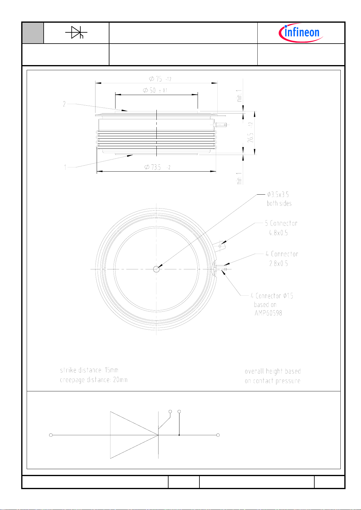
Kriechstrecke
creepage distance
Schwingfestigkeit
vibration resistance
Seite 3
page 3
F 20...45 kN
Gate (flat)
Gate (round, based on AMP 60598)
Kathode / cathode
G typ. 600 g
20 mm
f = 50 Hz 50 m/s²
A 2,8x0,5
A 4,8x0,5
Ø 1,5
mm
mm
mm
IFBIP D AEC, 2008-09-19, H.Sandmann
54/08 2/10 Seite/page
N
A
Datenblatt / Data sheet
Netz-Thyristor
Phase Control Thyristor
Massbild
T1220N
12
IFBIP D AEC, 2008-09-19, H.Sandmann
4 5
1: Anode / Anode
2: Kathode / Cathode
4: Gate
5: Hilfskathode/
54/08 3/10 Seite/page
Auxiliary Cathode

N
A
−
=
τ
Datenblatt / Data sheet
Netz-Thyristor
Phase Control Thyristor
Analytische Elemente des transienten Wärmewiderstandes Z
R,t – Werte
Diagramme
Kühlung /
Diagramme
Cooling
beidseitig
two-sided
anodenseitig
anode-sided
kathodenseitig
cathode-sided
Analytische Funktion / Analytical function:
Analytical elements of transient thermal impedance Z
Pos. n 1 2 3 4 5 6 7
R
[°C/W] 0,00022 0,00110 0,00102 0,00283 0,00608 0,00575 -
thn
τ
[s]
n
R
[°C/W] 0,00065 0,0019 0,00239 0,00381 0,00425 0,02 -
thn
τ
[s]
n
R
[°C/W] 0,00055 0,00206 0,00604 0,00551 0,02084 - -
thn
τ
[s]
n
T1220N
für DC
thJC
n
max
Σ
n=1
thJC
for DC
thnthJC
-t
n
e1RZ
Trans. Wärmewid. beidseitig
0,00136 0,00306 0,01390 0,06620 0,51200 1,49000 -
0,00160 0,0091 0,07910 0,26000 1,73600 7,21 -
0,00140 0,00857 0,15400 2,58000 7,00700 - -
0,04
0,03
0,02
[°C/W]
thJC
Z
0,01
0,00
0,001 0,01 0,1 1 10 100
Transienter innerer Wärmewiderstand für DC / Transient thermal impedance for DC
Z
thJC
a - Anodenseitige Kühlung / Anode-sided cooling
b - Beidseitige Kühlung / Two-sided cooling
c - Kathodenseitige Kühlung / Cathode-sided cooling
t [s]
= f(t)
c
a
b
IFBIP D AEC, 2008-09-19, H.Sandmann
54/08 4/10 Seite/page

N
A
Datenblatt / Data sheet
Netz-Thyristor
Phase Control Thyristor
Erhöhung des Z
Rise of Z
th DC
Kühlung / Cooling Θ = 180° Θ = 120° Θ = 90° Θ = 60° Θ = 30°
beidseitig
two-sided
anodenseitig
anode-sided
kathodenseitig
cathode-sided
bei Sinus und Rechteckströmen mit unterschiedlichen Stromflusswinkeln Θ
th DC
for sinewave and rectangular current with different current conduction angles Θ
∆Z
th Θ rec
[°C/W]
∆Z
th Θ sin
[°C/W]
∆Z
th Θ rec
[°C/W]
∆Z
th Θ sin
[°C/W]
∆Z
th Θ rec
[°C/W]
∆Z
th Θ sin
[°C/W]
Durchlasskennlinie
0,00188 0,00316 0,00413 0,00547 0,00745
0,00135 0,00198 0,00282 0,00416 0,00646
0,00185 0,00302 0,00393 0,00523 0,00727
0,00131 0,00187 0,00263 0,00388 0,00622
0,00185 0,00302 0,00390 0,00517 0,00724
0,00132 0,00186 0,00259 0,00381 0,00614
T1220N
∆Z
th Θ rec
/ ∆Z
th Θ sin
[A]
T
i
Z
Z
7.000
6.000
5.000
4.000
3.000
2.000
1.000
0
1 1,2 1,4 1,6 1,8 2 2,2 2,4 2,6 2,8 3
th Θ rec
th Θ sin
= Z
= Z
V
T
th DC
th DC
[V]
+ ∆Z
+ ∆Z
th Θ rec
th Θ sin
Tvj = T
vj max
Grenzdurchlasskennlinie / Limiting on-state characteristic i
IFBIP D AEC, 2008-09-19, H.Sandmann
= f(vT)
T
T
= Tvj
vj
max
54/08 5/10 Seite/page
N
A
Datenblatt / Data sheet
Netz-Thyristor
Phase Control Thyristor
4000
3500
[W]
TAV
P
3000
2500
2000
1500
1000
500
0
0°
0 200 400 600 800 1000 1200 1400 160 0 1800
T1220N
Durchlassverluste
90°
TAV
60°
[A]
0
180°
θ = 30°
I
120°
180°
Durchlassverlustleistung / On-state power loss P
Parameter: Stromflusswinkel Θ / Current conduction angle Θ
Sinusförmiger Strom / Sinusoidal current
TAV
= f(I
TAV
)
140
120
0°
0
100
80
[°C]
C
T
60
40
20
0 200 400 600 800 1000 1200 1400 1600 1800
[A]
I
TAV
180°
180°120°90°60°θ = 30°
Höchstzulässige Gehäusetemperatur / Maximum allowable case temperature T
Parameter: Stromflusswinkel Θ / Current conduction angle Θ
IFBIP D AEC, 2008-09-19, H.Sandmann
Sinusförmiger Strom / Sinusoidal current
Beidseitige Kühlung / Two-sided cooling
54/08 6/10 Seite/page
= f(I
C
TAV
)
N
A
Datenblatt / Data sheet
Netz-Thyristor
Phase Control Thyristor
5000
4000
3000
[W]
TAV
P
2000
1000
0°
0
0 500 1000 1500 2000 2500 3000
0
θ = 30°
180°
T1220N
Tc
60°
90°
I
TAV
DC
180°
120°
[A]
= f(I
Durchlassverlustleistung / On-state power loss P
TAV
TAV
)
Rechteckförmiger Strom / Rectangular current
Parameter: Stromflusswinkel Θ / Current conduction angle Θ
140
120
0°
0
100
80
[°C]
C
T
60
40
DC180°120°90°60°θ = 30°
20
0 500 1000 1500 2000 2500 3000
[A]
I
TAV
Höchstzulässige Gehäusetemperatur / Maximum allowable case temperature T
Rechteckförmiger Strom / Rectangular current
Beidseitige Kühlung / Two-sided cooling
Parameter: Stromflusswinkel Θ / Current conduction angle Θ
= f(I
C
TAV
)
180°
IFBIP D AEC, 2008-09-19, H.Sandmann
54/08 7/10 Seite/page

N
A
Datenblatt / Data sheet
Netz-Thyristor
Phase Control Thyristor
10
T1220N
Steuerkennlinie
[V]
G
v
1
=
vj max
T
+125°C
=
vj
T
+25°C
=
vj
T
-4 0 °C
0,1
10 100 1000 10000
i
[mA]
G
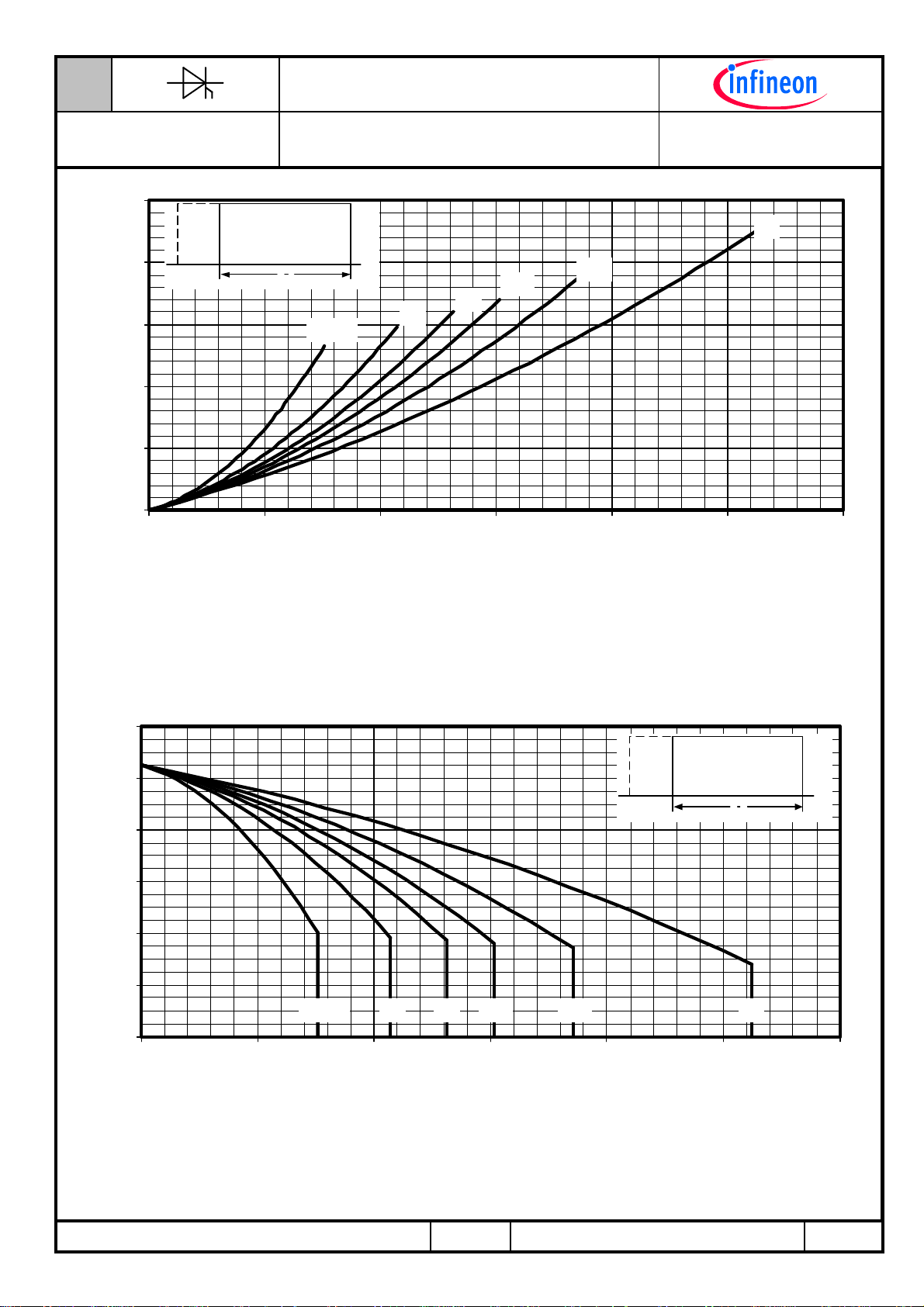
Höchstzulässige Spitzensteuerverlustleistung / Maximum rated peak gate power dissipation P
Steuercharakteristik v
Gate characteristic v
a - 20W / 10ms b - 40W / 1ms c - 60W / 0,5ms
= f (iG) mit Zündbereichen für VD = 12 V
G
= f (iG) with triggering area for VD = 12 V
G
Zündverzug
10000
[µAs]
r
Q
a
= f (tg) :
GM
iTM = 2000A
1000A
c
b
500A
200A
100A
50A
20A
1000
1 10 100
Sperrverzögerungsladung / Recovered charge Q
Parameter: Durchlassstrom / On-state current iTM
IFBIP D AEC, 2008-09-19, H.Sandmann
Tvj= T
, vR ≤ 0,5 V
vjmax
54/08 8/10 Seite/page
-di/dt [A/µs]
, V
RRM
RM
= 0,8 V
RRM
= f(di/dt)
r
N
A
Datenblatt / Data sheet
Netz-Thyristor
Phase Control Thyristor
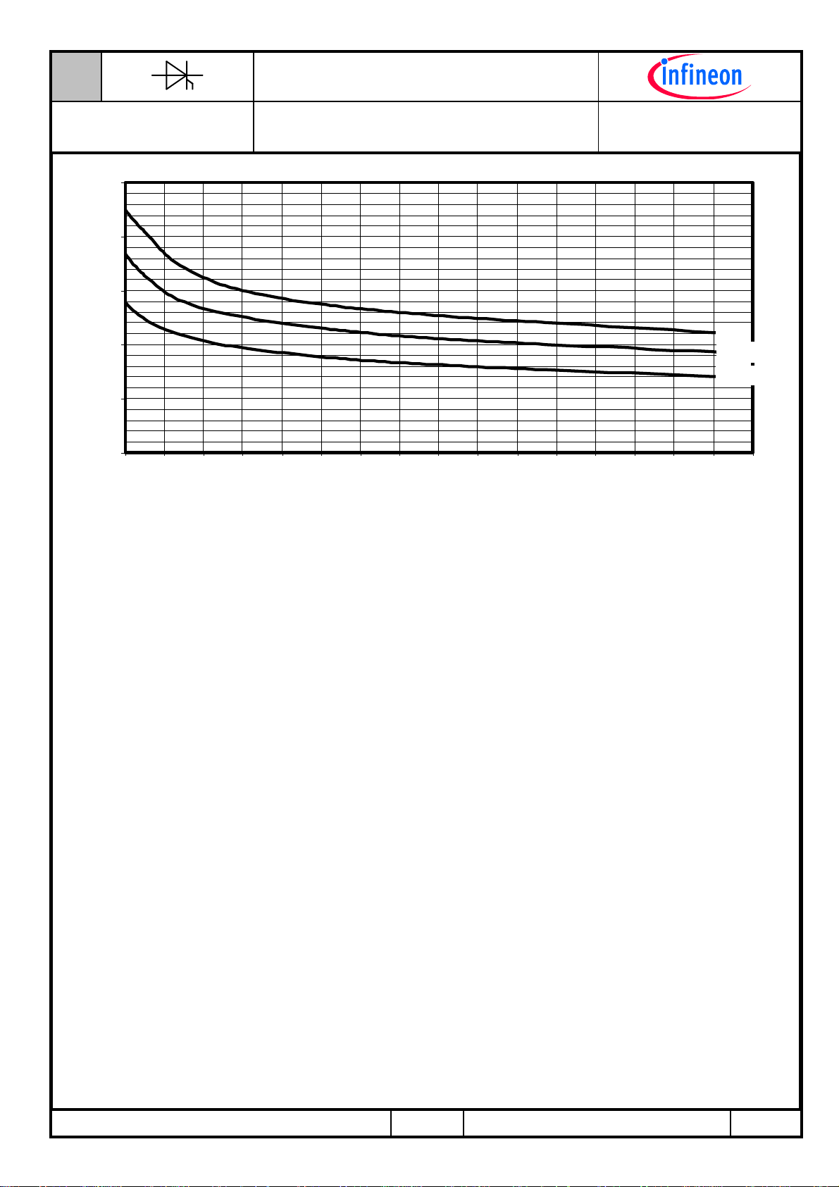
25
20
15
[kA]
T(OV)M
I
10
5
0
1234567891011121314151617
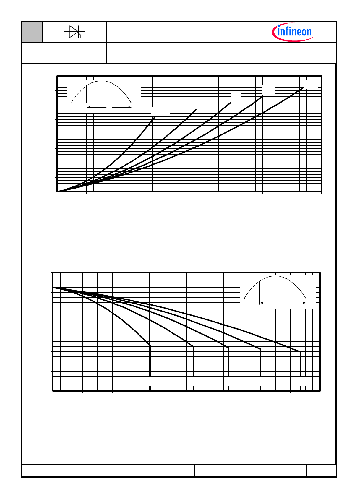
Typische Abhängigkeit des Grenzstromes I
Typical dependency of maximum overload on-state current I
sinusoidal half waves at 50Hz. Parameter: peak reverse voltage V
T1220N
Anzahl Pulse bei 50Hz Sinus Halbwellen
Number of pulses for 50Hz sinusoidal half waves
von der Anzahl für eine Folge von Sinus
Halbwellen bei 50Hz. Parameter: Rückwärtsspannung V
I
= f (pulses, VRM) ; Tvj = T
T(OV)M
T(OV)M
as a number of a sequence of
T(OV)M
vjmax
RM
0-50 V
0,33 VRRM
0,67 VRRM
RM
IFBIP D AEC, 2008-09-19, H.Sandmann
54/08 9/10 Seite/page

N
A
Datenblatt / Data sheet
Netz-Thyristor
Phase Control Thyristor
Nutzungsbedingungen
Die in diesem Produktdatenblatt enthaltenen Daten sind ausschließlich für technisch geschultes Fachpersonal bestimmt. Die
Beurteilung der Geeignetheit dieses Produktes für die von Ihnen anvisierte Anwendung sowie die Beurteilung der
Vollständigkeit der bereitgestellten Produktdaten für diese Anwendung obliegt Ihnen bzw. Ihren technischen Abteilungen.
In diesem Produktdatenblatt werden diejenigen Merkmale beschrieben, für die wir eine liefervertragliche Gewährleistung
übernehmen. Eine solche Gewährleistung richtet sich ausschließlich nach Maßgabe der im jeweiligen Liefervertrag enthaltenen
Bestimmungen. Garantien jeglicher Art werden für das Produkt und dessen Eigenschaften keinesfalls übernommen.
Sollten Sie von uns Produktinformationen benötigen, die über den Inhalt dieses Produktdatenblatts hinausgehen und
insbesondere eine spezifische Verwendung und den Einsatz dieses Produktes betreffen, setzen Sie sich bitte mit dem für Sie
zuständigen Vertriebsbüro in Verbindung (siehe www.infineon.com). Für Interessenten halten wir Application Notes bereit.
Aufgrund der technischen Anforderungen könnte unser Produkt gesundheitsgefährdende Substanzen enthalten. Bei
Rückfragen zu den in diesem Produkt jeweils enthaltenen Substanzen setzen Sie sich bitte ebenfalls mit dem für Sie
zuständigen Vertriebsbüro in Verbindung.
Sollten Sie beabsichtigen, das Produkt in Anwendungen der Luftfahrt, in gesundheits- oder lebensgefährdenden oder
lebenserhaltenden Anwendungsbereichen einzusetzen, bitten wir um Mitteilung. Wir weisen darauf hin, dass wir für diese Fälle
- die gemeinsame Durchführung eines Risiko- und Qualitätsassessments;
- den Abschluss von speziellen Qualitätssicherungsvereinbarungen;
- die gemeinsame Einführung von Maßnahmen zu einer laufenden Produktbeobachtung dringend
empfehlen und gegebenenfalls die Belieferung von der Umsetzung solcher Maßnahmen abhängig
machen.
Soweit erforderlich, bitten wir Sie, entsprechende Hinweise an Ihre Kunden zu geben.
Inhaltliche Änderungen dieses Produktdatenblatts bleiben vorbehalten.
Terms & Conditions of usage
The data contained in this product data sheet is exclusively intended for technically trained staff. You and your technical
departments will have to evaluate the suitability of the product for the intended application and the completeness of the product
data with respect to such application.
This product data sheet is describing the characteristics of this product for which a warranty is granted. Any such warranty is
granted exclusively pursuant the terms and conditions of the supply agreement. There will be no guarantee of any kind for the
product and its characteristics.
Should you require product information in excess of the data given in this product data sheet or which concerns the specific
application of our product, please contact the sales office, which is responsible for you (see www.infineon.com). For those that
are specifically interested we may provide application notes.
Due to technical requirements our product may contain dangerous substances. For information on the types in question please
contact the sales office, which is responsible for you.
Should you intend to use the Product in aviation applications, in health or live endangering or life support applications, please
notify. Please note, that for any such applications we urgently recommend
- to perform joint Risk and Quality Assessments;
- the conclusion of Quality Agreements;
- to establish joint measures of an ongoing product survey, and that we may make delivery depended on
the realization of any such measures.
If and to the extent necessary, please forward equivalent notices to your customers.
Changes of this product data sheet are reserved.
T1220N
IFBIP D AEC, 2008-09-19, H.Sandmann
54/08 10/10 Seite/page
 Loading...