

Page 1
User guide Please read the Important notice and the Safety precautions and the Warnings V 1.0.1
www.infineon.com page 1 of 45 2021-01-27
UG2020-30
REF-AIRCON-C302A-IM564 user guide
Air conditioner application reference design kits
About this document
Scope and purpose
This user guide provides an overview of the reference board REF-AIRCON-C302A-IM564 including its main
features, key test results and mechanical dimensions.
The REF-AIRCON-C302A-IM564 is a full-featured starter kit, turnkey motor drive designed for high-performance,
high-efficiency permanent magnet synchronous motor (PMSM) drive applications, including all of the required
elements for air conditioner applications, such as IMC302A iMOTIONTM controller, 1ED44175 PFC gate driver and
PFC-integrated CIPOS
TM
Mini IPM IM564-X6D.
The starter kit features and demonstrates Infineon’s CIPOS
TM
Mini IPM and advanced motion control engine
(MCE 2.0) technology for PMSM/BLDC motor and PFC driver up to a rating of 600 V and 20 A. It is optimized for
major home appliances like air conditioner compressors, fans, pumps and other motor drive applications.
Note: Please note that this product is not qualified according to the AEC Q100 or AEC Q101 documents of
the Automotive Electronics Council.
Intended audience
This application note is intended for all technical specialists who are familiar with air conditioner control and
electronics converters. The reference design is intended to be used under laboratory conditions only by trained
specialists.
Reference board
The Infineon products are embedded on this PCB with functions and form factor close to a commercial design.
PCB and auxiliary circuits are optimized for the final design.
Note: Boards do not necessarily meet safety, EMI, quality standards (for example UL, CE) requirements.
Page 2

User guide 2 of 45 V 1.0.1
2021-01-27
REF-AIRCON-C302A-IM564 user guide
Air conditioner application reference design kits
Important notice
Important notice
“Evaluation Boards and Reference Boards” shall mean products embedded on a printed circuit board
(PCB) for demonstration and/or evaluation purposes, which include, without limitation, demonstration,
reference and evaluation boards, kits and design (collectively referred to as “Reference Board”).
Environmental conditions have been considered in the design of the Evaluation Boards and Reference
Boards provided by Infineon Technologies. The design of the Evaluation Boards and Reference Boards
has been tested by Infineon Technologies only as described in this document. The design is not qualified
in terms of safety requirements, manufacturing and operation over the entire operating temperature
range or lifetime.
The Evaluation Boards and Reference Boards provided by Infineon Technologies are subject to functional
testing only under typical load conditions. Evaluation Boards and Reference Boards are not subject to the
same procedures as regular products regarding returned material analysis (RMA), process change
notification (PCN) and product discontinuation (PD).
Evaluation Boards and Reference Boards are not commercialized products, and are solely intended for
evaluation and testing purposes. In particular, they shall not be used for reliability testing or production.
The Evaluation Boards and Reference Boards may therefore not comply with CE or similar standards
(including but not limited to the EMC Directive 2004/EC/108 and the EMC Act) and may not fulfill other
requirements of the country in which they are operated by the customer. The customer shall ensure that
all Evaluation Boards and Reference Boards will be handled in a way which is compliant with the relevant
requirements and standards of the country in which they are operated.
The Evaluation Boards and Reference Boards as well as the information provided in this document are
addressed only to qualified and skilled technical staff, for laboratory usage, and shall be used and
managed according to the terms and conditions set forth in this document and in other related
documentation supplied with the respective Evaluation Board or Reference Board.
It is the responsibility of the customer’s technical departments to evaluate the suitability of the
Evaluation Boards and Reference Boards for the intended application, and to evaluate the completeness
and correctness of the information provided in this document with respect to such application.
The customer is obliged to ensure that the use of the Evaluation Boards and Reference Boards does not
cause any harm to persons or third party property.
The Evaluation Boards and Reference Boards and any information in this document is provided "as is"
and Infineon Technologies disclaims any warranties, express or implied, including but not limited to
warranties of non-infringement of third party rights and implied warranties of fitness for any purpose, or
for merchantability.
Infineon Technologies shall not be responsible for any damages resulting from the use of the Evaluation
Boards and Reference Boards and/or from any information provided in this document. The customer is
obliged to defend, indemnify and hold Infineon Technologies harmless from and against any claims or
damages arising out of or resulting from any use thereof.
Infineon Technologies reserves the right to modify this document and/or any information provided
herein at any time without further notice.
Page 3
User guide 3 of 45 V 1.0.1
2021-01-27
REF-AIRCON-C302A-IM564 user guide
Air conditioner application reference design kits
Safety precautions
Safety precautions
Please note the following warnings regarding the hazards associated with development systems.
Table 1 Safety precautions
Warning: The DC link potential of this board is up to 400 VDC. When measuring voltage
waveforms by oscilloscope, high voltage differential probes must be used. Failure to do
so may result in personal injury or death.
Warning: The reference board contains DC bus capacitors which take time to
discharge after removal of the main supply. Before working on the drive system, wait
five minutes for capacitors to discharge to safe voltage levels. Failure to do so may
result in personal injury or death. Darkened display LEDs are not an indication that
capacitors have discharged to safe voltage levels.
Warning: The reference board is connected to the grid input during testing. Hence,
high-voltage differential probes must be used when measuring voltage waveforms by
oscilloscope. Failure to do so may result in personal injury or death. Darkened display
LEDs are not an indication that capacitors have discharged to safe voltage levels.
Warning: Remove or disconnect power from the drive before you disconnect or
reconnect wires, or perform maintenance work. Wait five minutes after removing
power to discharge the bus capacitors. Do not attempt to service the drive until the bus
capacitors have discharged to zero. Failure to do so may result in personal injury or
death.
Caution: The heat sink and device surfaces of the reference board may become hot
during testing. Hence, necessary precautions are required while handling the board.
Failure to comply may cause injury.
Caution: Only personnel familiar with the drive, power electronics and associated
machinery should plan, install, commission and subsequently service the system.
Failure to comply may result in personal injury and/or equipment damage.
Caution: The reference board contains parts and assemblies sensitive to electrostatic
discharge (ESD). Electrostatic control precautions are required when installing, testing,
servicing or repairing the assembly. Component damage may result if ESD control
procedures are not followed. If you are not familiar with electrostatic control
procedures, refer to the applicable ESD protection handbooks and guidelines.
Caution: A drive that is incorrectly applied or installed can lead to component damage
or reduction in product lifetime. Wiring or application errors such as undersizing the
motor, supplying an incorrect or inadequate AC supply, or excessive ambient
temperatures may result in system malfunction.
Caution: The reference board is shipped with packing materials that need to be
removed prior to installation. Failure to remove all packing materials that are
unnecessary for system installation may result in overheating or abnormal operating
conditions.
Page 4

User guide 4 of 45 V 1.0.1
2021-01-27
REF-AIRCON-C302A-IM564 user guide
Air conditioner application reference design kits
The board at a glance
Table of contents
About this document ....................................................................................................................... 1
Important notice ............................................................................................................................ 2
Safety precautions .......................................................................................................................... 3
Table of contents ............................................................................................................................ 4
1 The board at a glance .............................................................................................................. 5
1.1 Delivery content ...................................................................................................................................... 5
1.2 Block diagram .......................................................................................................................................... 5
1.3 Main features ........................................................................................................................................... 7
1.4 Board parameters and technical data .................................................................................................... 7
2 System and functional description ........................................................................................... 9
2.1 Getting started with REF-AIRCON-C302A-IM564 .................................................................................... 9
2.2 Description of the functional blocks ..................................................................................................... 15
2.2.1 Overview of IMC302A ........................................................................................................................ 15
2.2.2 Overview of IM564-X6D .................................................................................................................... 16
2.2.3 Overview of 1ED44175 ..................................................................................................................... 18
2.2.4 Overview of ICE5AR4770BZS ............................................................................................................ 19
2.2.5 Design tips for direct motor current sensing .................................................................................. 20
2.2.6 Design tips for PFC current sensing ................................................................................................. 22
3 System design ...................................................................................................................... 24
3.1 Inverter section of REF-AIRCON-C302A-IM564 ..................................................................................... 24
3.2 PFC section of REF-AIRCON-C302A-IM564 ............................................................................................ 25
3.3 Auxiliary power supply .......................................................................................................................... 26
3.4 PCB Layout for REF-AIRCON-C302A-IM564 ........................................................................................... 27
3.5 Bill of material ....................................................................................................................................... 29
3.6 Connector details .................................................................................................................................. 30
3.7 Test points ............................................................................................................................................. 31
4 System performance ............................................................................................................. 32
4.1 Thermal characterization...................................................................................................................... 32
4.2 NTC thermistor characteristics and overheat protection .................................................................... 32
4.3 Motor overcurrent protection (OCP) test ............................................................................................. 35
4.4 PFC overcurrent protection test ........................................................................................................... 38
4.5 DC bus sensing and overvoltage protection ........................................................................................ 40
4.6 PFC performance test ............................................................................................................................ 42
5 References and appendices .................................................................................................... 43
5.1 Abbreviations and definitions ............................................................................................................... 43
5.2 References ............................................................................................................................................. 43
5.3 Ordering details and other information ............................................................................................... 43
Revision history............................................................................................................................. 44
Page 5
User guide 5 of 45 V 1.0.1
2021-01-27
REF-AIRCON-C302A-IM564 user guide
Air conditioner application reference design kits
The board at a glance
1 The board at a glance
The REF-AIRCON-C302A-IM564 is a part of Infineon’s CIPOS
TM
Mini IPM and iMOTION™ reference design kits. It is
designed to provide ready-to-use, air conditioner solutions based on Infineon’s PFC-integrated CIPOS
TM
Mini
IPM and advanced motion control engine (MCE 2.0) technology.
The REF-AIRCON-C302A-IM564 is an optimized design for 1400 ~ 2500 W power air conditioner applications. It
allows fast prototyping and fast time to market. It is available through regular Infineon distribution partners as
well as on Infineon's website. The main features of this board are described in this document, whereas the
remaining paragraphs provide information to enable the customers to copy and modify the design for
production according to their own specific requirements.
1.1 Delivery content
The board is equipped with all assembly groups for sensorless field-oriented control (FOC), and reserved
interface for BLDC/AC fan control, relays and 4-way valve control and 3-channel temperature sensing circuits,
so that it can be easily used for air conditioners and similar home applications.
It provides a single-phase AC connector, an EMI filter and soft power-up circuit, input rectifier, DC bus
capacitors, on-board PFC inductor emitter shunts for current sensing and overcurrent protection (OCP),
thermistor output and a voltage divider for DC-link voltage measurement.
The REF-AIRCON-C302A-IM564 reference design also contains a CoolSETTM based flyback auxiliary power supply
to provide 15 V, 12 V & 5 V.
1.2 Block diagram
The block diagram of the REF-AIRCON-C302A-IM564 is depicted in Figure 1.
M
HVIC
IMC302A
IM564-X6D Inverter Section
L
N
15V
PWM
VFO
Itrip
PWM
VTH
GK
DCBsense
5V
IM564-X6D
PFC Section
PFC
Current
sensing
VAC+
VAC-
Power
Supply
IFB
Gate
Driver
PFC_PWM
EMI Filter
& Soft
Power Up
Circuit
IPFC
PFC_Trip
Temperature
sensing
EEPROM
IDU COM
AC Fan/BLDC Fan
Debug Relays
Figure 1 Block diagram of the REF-AIRCON-C302A-IM564
Page 6
User guide 6 of 45 V 1.0.1
2021-01-27
REF-AIRCON-C302A-IM564 user guide
Air conditioner application reference design kits
The board at a glance
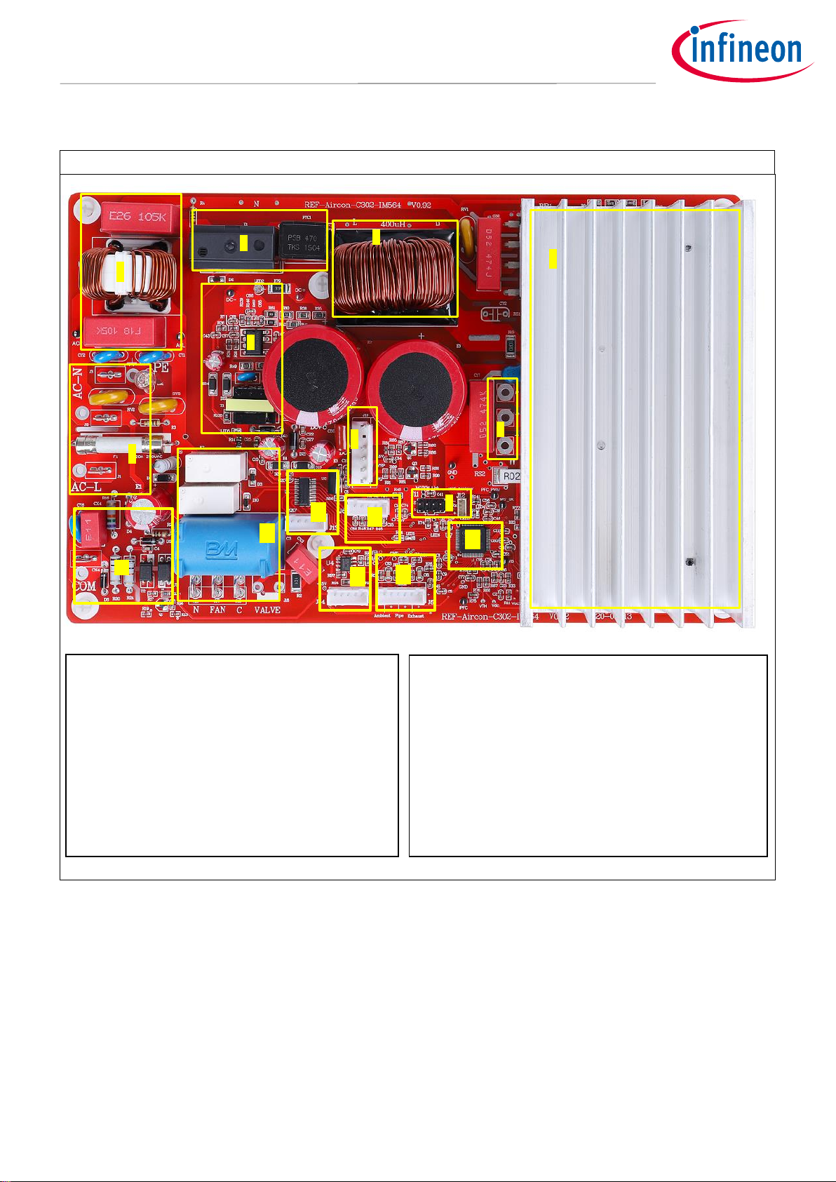
Figure 2 points out the functional groups on the top side of the REF-AIRCON-C302A-IM564 reference design:
Figure 2 Functional groups of the REF-AIRCON-C302A-IM564 reference design
2
1
10
7
9
1. 220 VAC & PE input connector
2. EMI filter
3. In-rush relay control
4. On-board PFC inductor
5. Heat sink (IM564 + 1ED44175 + input rectifier)
6. UVW motor phase connector
7. iMOTIONTM link connector, UART 0 & UART1
8. External BLDC fan VSP control
9. Auxiliary power supply
3
4
5
6
12
11
8
10. AC fan and 4-way valve relay control
11. Single-wire UART interface to IDU
12. EEV connector
13. UART tester connector
14. EEPROM
15. Temperature sensing
16. IMC302A
13 14 15
16
Page 7

User guide 7 of 45 V 1.0.1
2021-01-27
REF-AIRCON-C302A-IM564 user guide
Air conditioner application reference design kits
The board at a glance
1.3 Main features
The REF-AIRCON-C302A-IM564 board is an optimized reference design for 220 V air conditioner applications,
which contains iMOTION™ controller IMC302A, 20 A, 600 V PFC-integrated CIPOS™ Mini IPM and 1ED44175 PFC
gate driver.
Major REF-AIRCON-C302A-IM564 characteristics include:
• Input voltage 85~265 V
AC
• Maximum 2500 W at 220 V
AC
power input with forced air cooling
• Maximum 1400 W at 220 V
AC
power input without forced air cooling
• 20 A, 600 V PFC-integrated CIPOS™ Mini IPM
• On-board 10 A, 400 µH PFC inductor for 40 kHz PFC operation
• VSP host interface for external BLDC fan
• AC fan and 4-way valve control relay
• Single-wire UART communication interface to IDU
• Overcurrent and over temperature protection, fault diagnostic LED output
• Auxiliary power supply with 15 V, 12 V and 5 V
• PCB is 250 mm × 157 mm, 2 layers, 1 oz. copper
• RoHS compliant
1.4 Board parameters and technical data
Table 2 depicts the key specifications of the reference design of REF-AIRCON-C302A-IM564.
Table 2 REF-AIRCON-C302A-IM564 board specifications
Parameter
Symbol
Conditions / comments
Value
Unit
Input voltage
Vac
Optimized design for 220 VAC applications
85 ~ 265
V
rms
Maximum input current
I
ac(max1)
Input 220 VAC, Ta=25C, natural cooling mode
6
A
rms
I
ac(max2)
Input 220 VAC, Ta=25C, with 1 m/s wind cooling
12
A
rms
Maximum output power
P
in(max1)
Input 220 VAC, Motor f
PWM
= 6 kHz, PFC f
PWM
=40 kHz,
Ta=25°C, IPM TC = 105 °C , Natural cooling mode
1400
W
P
in(max2)
Input 220 VAC, Motor f
PWM
= 6 kHz, PFC f
PWM
=40 kHz,
Ta=25°C, IPM TC = 105 °C , 1 m/s force cooling mode
2500
W
Maximum motor current
I
mtr(max1)
Input 220 VAC, Motor f
PWM
= 6 kHz, PFC f
PWM
=40 kHz,
Ta=25°C, IPM TC = 105 °C , Natural cooling mode
6
A
rms
I
mtr(max2)
Input 220 VAC, Motor f
PWM
= 6 kHz, PFC f
PWM
=40 kHz,
Ta=25°C, IPM TC = 105 °C , 1 m/s force cooling mode
10
A
rms
DC bus voltage
Maximum DC bus voltage
V
dc(max)
DC bus capacitors are 450 V, 470 µF x 2
450
V
Minimum DC bus voltage
V
dc(min)
Aux power supply brown-in voltage
80
V
Page 8
User guide 8 of 45 V 1.0.1
2021-01-27
REF-AIRCON-C302A-IM564 user guide
Air conditioner application reference design kits
The board at a glance
Parameter
Symbol
Conditions / comments
Value
Unit
Current feedback
PFC shunt resistance
RS1
5 W shunt resistor with external OPA gain 14.7
15
mΩ
Motor shunt resistance
RS2
Direct AD sample (without external OPA)
20
mΩ Protections
Motor current protection
trigger level 1
MtrI
trip1
Wizard setup for OC trigger level, related to AD
range, shunt resistor RS2 and pull-up bias
16 1
A
peak
Motor current protection
trigger level 2
MtrI
trip2
Hardware comparator overcurrent protection,
related to RS2 and IM564’s Itrip threshold
26.2
A
peak
PFC current protection
trigger level 1
PFCI
trip1
IMC302A’s internal comparator for cycle-by-cycle
OCP, trip level can be adjusted by R50 & R55
20 2
A
peak
PFC current protection
trigger level 2
PFCI
trip2
PFC driver local protection for 1ED44175 driver,
trip level can be adjusted by RS1, R66 & R71
33.3
A
peak
Thermal protection level
T
protection
Temperature gap between junction and NTC
sensor needs to be considered
90
°C
Auxiliary power supply 1 – 15 V
Output voltage
V
out1
Used for IPM driver
15 ± 2%
V
Maximum output current
I
out1
150
mA
Auxiliary power supply 2 – 12 V
Output voltage
V
out2
Used for relay control
12 ± 10%
V
Maximum output current
I
out2
300
mA
Auxiliary power supply 3 – 5 V
Output voltage
V
out2
Used for IMC controller and protection circuits
5 ± 1%
V
Maximum output current
I
out2
200
mA PCB characteristics
Dimension
Length × width × height
250×157
×65
mm
Material
FR4, 1.6 mm thickness, 1 oz. PCB
System environment
Ambient temperature
Ta
Non-condensing, maximum RH of 95%
0 ~ 50
°C
1
For iMOTION™ IC IMCxxx, there are three types of Gatekill input source options in MCEWizard setup: Gatekill-pin, Comparator and
both. If you select “comparator” mode, the external Gatekill signal will not be used, and the IFB will be compared by the internal
comparator with the “Device overcurrent trigger level setting” value set in MCEWizard.
2
For iMOTION™ IC IMC302 PFC overcurrent protection, there are two options in MCEWizard setup.
If you select “Enable cycle by cycle” mode, the PWM output immediately goes to logic LOW when the inductor current exceeds the
pre-determined OCP threshold, and re-starts at following PWM cycle.
For “Disable” mode, PFC state machine would shift from RUN state to FAULT state when inductor current exceeds the pre-
determined OCP threshold for a duration specified by parameter “PFC_GateKillTime”, only Fault_clear command can make it back
to STOP/RUN mode, which means latch–off OCP.
Page 9
User guide 9 of 45 V 1.0.1
2021-01-27
REF-AIRCON-C302A-IM564 user guide
Air conditioner application reference design kits
System and functional description
2 System and functional description
This chapter provides more function block details on setting up the system, and getting started with the
iMOTION™ development platform with the REF-AIRCON-C302A-IM564 reference design.
2.1 Getting started with REF-AIRCON-C302A-IM564
The REF-AIRCON-C302A-IM564 reference designs are shipped with embedded firmware and default
parameters.
A 6-pole, GK6063-6AC31 motor is used for the default DEMO functions, whose maximum speed is 2500 RPM and
maximum power is 3 KW. Please note that motor parameters need to be double-checked in MCEWizard for a
real air conditioner motor.
An iMOTIONTM Link or third party isolated USB-to-UART cable is needed to bridge the PC/debugger side and
motor drive system (the target iMOTION™ device, hot side) with 1 kV DC galvanic isolation.
The iMOTION™ software tools, MCEDesigner and MCEWizard, are required to initially set up the system, as well
as to control and fine-tune the system performance to match the user’s exact needs. These tools are available
for download via the Infineon website (https://www.infineon.com/cms/en/product/power/motor-control-
ics/digital-motor-controller-imotion/imc302a-f064/#!tools ). Please visit this page periodically to check for
tool/software updates.
After downloading and installing the iMOTION™ PC tools, MCEWizard and MCEDesigner, the following steps need
to be executed in order to run the motor. Refer to MCEWizard and MCEDesigner documentation for more
information.
Figure 3 shows the basic system connection using REF-AIRCON-C302A-IM564 to run motor with MCEDesigner:
Figure 3 System connection example
iMOTION Link Connector
(USB-to-UART)
AC
Power
Input
Motor Phase
Outputs
Page 10
User guide 10 of 45 V 1.0.1
2021-01-27
REF-AIRCON-C302A-IM564 user guide
Air conditioner application reference design kits
System and functional description
Figure 4 shows the MCEWizard welcome page and interface of MCEDesigner.
Figure 4 MCEWizard welcome page and MCEDesigner interface
Page 11
User guide 11 of 45 V 1.0.1
2021-01-27
REF-AIRCON-C302A-IM564 user guide
Air conditioner application reference design kits
System and functional description
Here are the steps needed to run the motor:
1. Connect iMOTION
TM
Link’s 8-pin cable to J11 with default pin order (align connector orientation markings
with PCB silkscreen markings), and connect PC-USB connector to iMOTIONTM Link.
2. Use MCEWizard to enter the target motor’s system and operating parameters, as well as evaluation board’s
hardware parameters, which will then be used to calculate the digital parameter set of the controller
representing the complete motor drive system.
3. After system and operating parameters are set, go to the “Verify & Save Page” and click on “Calculate
Parameters” button. If no errors are reported, then save the drive parameter set into your project directory
by clicking “Export to MCEDesigner file (.txt)” (Figure 5); if an error is detected, double-click on the error
message (highlighted in RED) and adjust the related parameter. The saved drive system parameter file will
be later used by the MCEDesigner in step 9.
(Please refer to MCEWizard_V2.3.0.0 User Guide.pdf for more details, which is in MCEWizard’s install path)
Figure 5 MCEWizard Verify and Save page
4. Connect 220 V AC power supply and UVW outputs to the motor.
5. Turn on 220 V AC power supply, LED2 and LED5 ON.
6. Start MCEDesigner tool and open MCEDesigner default configuration file (.irc) for IMC302A device
(IMC302A_Vxxx.irc) by clicking “File” > “Open”.
(IMC302A_Vxxx.irc file is included in downloaded “IMC302A MCE Software Package”)
MCEDesigner should automatically connect to the REF-AIRCON-C302A-IM564 board using default COM port
(Indicated by green circle next to “COMx Up” status in the bottom frame of the MCEDesigner GUI).
Page 12
User guide 12 of 45 V 1.0.1
2021-01-27
REF-AIRCON-C302A-IM564 user guide
Air conditioner application reference design kits
System and functional description
If it cannot establish the connection due to incorrect COM port, change COM port by doing the following:
Click on the “System Page” window and then click on “Preferences > Connection > Connect using” and choose
one of the other available COM ports from the drop-down list.
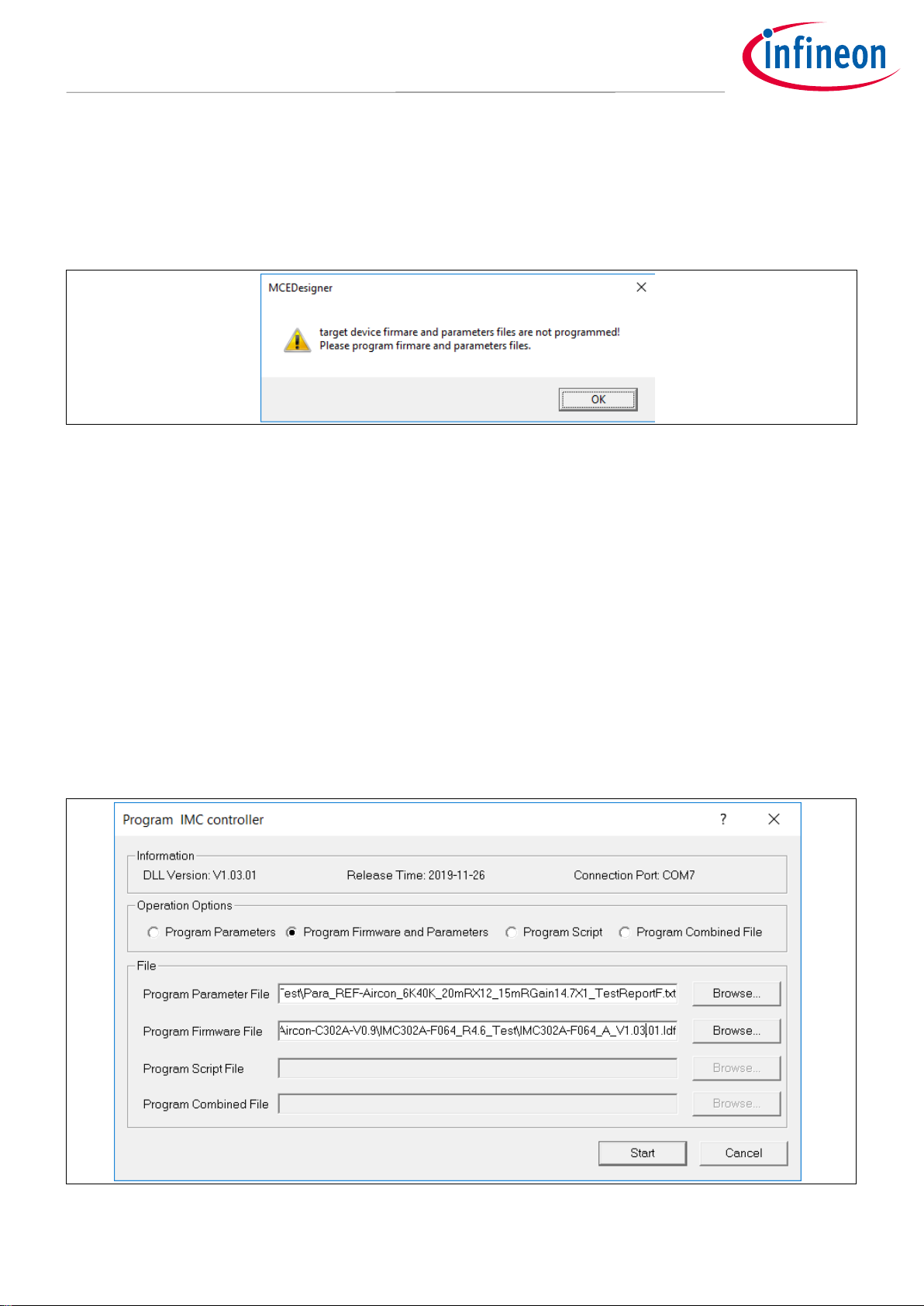
7. In case of blank IC: If the firmware has been erased from the IMC302A, a warning message will pop up saying
“Target device firmware and parameters file are not programmed! Please program firmware and parameters
file.” (Figure 6) See step 9 on how to obtain/program firmware and parameters.
Figure 6 MCEDesigner warning message
8. In case of blank IC: Do the following to program the firmware and the parameters’ file into the internal Flash
memory of iMOTION™ Control IC: Click on system page, click “Tools” > “Programmer” and select “Program
Firmware and Parameters,” shown as Figure 7 below. The encrypted firmware is available in IMC302A MCE
Software Package, regarding the parameters file, browse and select the .txt file in step 3.
(If blank IMC302A IC, MCEDesigner will pop up information “Target device firmware and parameter files are not
programmed!”) Program the MCE firmware and system parameters into the internal Flash memory of iMOTION™ IC by
clicking “Tools > Programmer “in the pull-down menu, and then clicking on the “Program Firmware and Parameter”
check box. Select right Parameter file and firmware file. Finally click “Start” button to program firmware and parameter.
Then click YES and then the OK button to update IRC file with parameter file; finally “Save As” the IRC file to your own file
name that contains COM config, Parameters & firmware file path information. (Please refer to MCEDesigner User
Guide.pdf and MCEDesigner_V2.3.0.0 Application Guide.pdf for more details, which is in MCEDesigner’s install path)
Red LED4 will flash on after the program is done.
Figure 7 MCEDesigner program page
Page 13
User guide 13 of 45 V 1.0.1
2021-01-27
REF-AIRCON-C302A-IM564 user guide
Air conditioner application reference design kits
System and functional description
9. Double click the “VF Diagnostic” function in Motor1 page, and monitor the motor current with oscilloscope.
If the motor current is not sinusoidal, change the target speed and Vd_Ext in VF Diagnostic sub-function,
then double-click “VF Diagnostic” until oscilloscope shows a steady sinusoidal current, with an amplitude of
30~50% motor rate current.
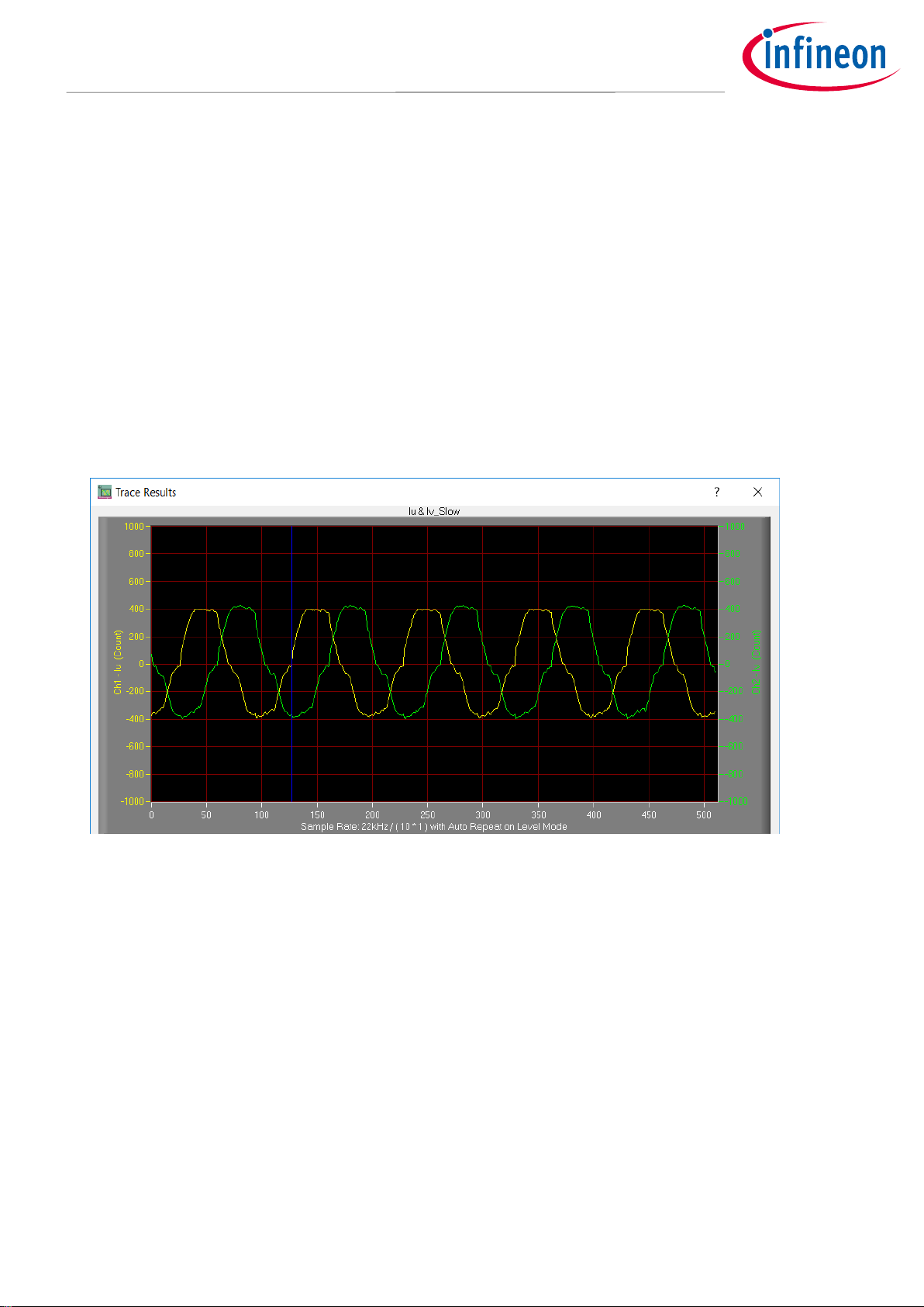
Double-click “Iu & Iv_Slow” in System page > Monitor Definitions; the motor current feedback should be
very clean and sinusoidal, as shown in Figure 8, otherwise please tune “Gating Propagation Delay & Phase
Shift Window Size” in MCEWizard. The sampled motor current amplitude should be over 300 cts ~500 cts
(corresponding to 30%~50% motor rate current); otherwise, the motor-current sample related hardware
and setup need tuning.
“VF Diagnostic” sub function can verify:
• If motor is correctly connected
• If MOS & gate driver work as expected
• If current sensing related parameters are correctly configured
• If PCB layout and DC bus decoupling have been done correctly
After “VF Diagnostic” is done, click STOP button (the red traffic light button) to stop PWM.
Figure 8 Trace waveform for Iu & Iv open loop diagnostic
10. Start the motor by clicking the green traffic light button in the control bar (or double-click Start Motor sub
function in Motor1 page, group of User Application Function Definitions); motor runs if above step goes well.
11. Check motor spin direction, adjust UVW connection order or set negative target speed in MCEDesigner if
direction is wrong.
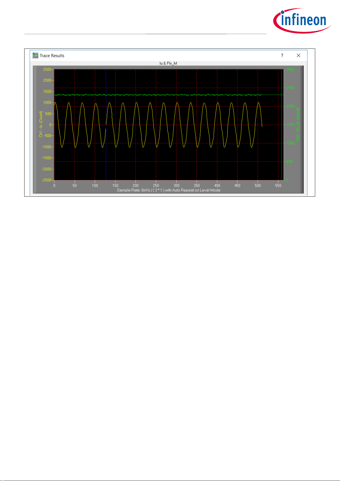
12. Set target speed to about 50% of MAX speed, start “Iu & Flx_M” trace with “Auto Repeat on Level”. As Figure
9. Flx_M is better within the range of 2000~2500 cts (rated value is 2048), and MUST be steady and DC-like.
Some key tips for better motor-performance tuning:
• If Flx_M is not steady (swinging or oscillating), double-check motor parameters, speed loop PI gain, flux Estimator
time constant and PLL PI bandwidth (parameters PLLKp & PLLKi) related setup.
• If Flx_M is very noisy, double-check current feedback and Vdc-related hardware and parameters.
• If Flx_M is far from 2048, “Motor Back EMF Constant (Ke)” needs to be adjusted in MCEWizard.
Page 14
User guide 14 of 45 V 1.0.1
2021-01-27
REF-AIRCON-C302A-IM564 user guide
Air conditioner application reference design kits
System and functional description
Figure 9 Trace waveform for Iu & Flx-M at 50% speed
13. Once the firmware has been programmed, in case a new parameters’ file has to be programmed, follow the
same instructions given in step 9. In this case, firmware programming is no longer needed and it is possible
to select the first option “Program Parameters.”
Note: For detailed information on controller programming, refer to AN2018-33 iMOTION™ 2.0 Device Programming,
MCEDesigner documentation and MCEWizard documentation.
Page 15

User guide 15 of 45 V 1.0.1
2021-01-27
REF-AIRCON-C302A-IM564 user guide
Air conditioner application reference design kits
System and functional description
2.2 Description of the functional blocks
The motor inverter and PFC convertor of the REF-AIRCON-C302A-IM564 reference design are implemented by
the IM564-X6D IPM module, and the PFC MOSFET gate driver is 1ED44175.
The control functions of the air conditioning system, motor and PFC are implemented by IMC302A.
Motor current sensing is single shunt mode, with lowest cost configuration of direct AD sample.
An external 14.7 X gain operational amplifiers (OPA) SGM8968-1 is used for PFC current sensing.
The flyback auxiliary power supply is based on fixed-frequency CoolSETTM ICE5AR4770BZS.
2.2.1 Overview of IMC302A
The IMC302A combined dual core computation, Motion Control Engine (MCE) and ARM® Cortex®-M0 based user
application controller (MCU). The internal block and application diagram is shown in Figure 10.
Figure 10 IMC302A internal block and application schematics diagram
Main features of the iMOTION™ controller IMC302A include:
Motion control engine (MCE)
MCE as ready-to-use controller solution for sensorless motor drives
Field-oriented control (FOC) for permanent magnet synchronous motor (PMSM)
Integrated protection features (overvoltage /undervoltage, overcurrent and over-temperature, etc.)
Current sensing via single shunt or leg shunt
Page 16

User guide 16 of 45 V 1.0.1
2021-01-27
REF-AIRCON-C302A-IM564 user guide
Air conditioner application reference design kits
System and functional description
Integrated analog comparators for overcurrent protection
Integrated scripting engine for application flexibility
Flexible host interface options for speed commands: UART, SPI, PWM or analog signal
Class B pre-certification (IEC60730) for MCE2.0 firmware
User application controller (MCU)
Arm® Cortex®-M0 based MCU with flexible peripherals and communication interfaces
48 / 96 MHz core / peripherals clock
8 Kbyte ROM, 16 Kbyte SRAM and 128 Kbyte FLASH memory (with ECC)
3.3 V or 5.0 V supply voltage options for controller
On-chip clock monitor
2.2.2 Overview of IM564-X6D
The IM564-X6D is a part of the CIPOS™ Mini IPM series, with CoolMOSTM power MOSFET and a rapid switching
diode for PFC stage. The IM564-X6D main application-related data are as follows:
Inverter section continuous output ability is 20 A at Tc = 25℃, and 15 A at Tc = 80℃
Inverter IGBT short-circuit withstand time is 5 µs
Recommended minimum input pulse width is 1 µs
Recommended external dead time of motor PWM is 1.5 µs
Maximum motor PWM carrier frequency is 20 kHz
PFC continuous input ability is 20 A at Tc = 25℃, and 15 A at Tc = 80℃,
Maximum PFC peak current is 40 A at Tc = 25℃.
Maximum PFC PWM carrier frequency is 150 kHz
Figure 11 illustrates the internal block diagram of IM564-X6D. Its main features include:
Fully isolated dual in-line molded module
Very low thermal resistance due to DCB substrate
Lead-free terminal plating and RoHS compliant
3.3 V, 5 V and 15 V input logic compatible
TRENCHSTOP™ IGBTs for Inverter and CoolMOS™ Power MOSFET for PFC
Rugged SOI gate driver technology with stability against transient and negative voltage
Allowable negative VS potential up to -11 V for signal transmission at VBS = 15 V
Integrated bootstrap diode, cross-conduction prevention and rapid switching emitter-controlled diode
Built-in NTC thermistor for temperature monitor
All of 6 switches turn off during OCP and undervoltage lockout
Sleep function is activated after ITRIP or undervoltage lockout
Fast-track shutdown allows low-side outputs to be turned off faster than high-side outputs by about 200 ns
Page 17

User guide 17 of 45 V 1.0.1
2021-01-27
REF-AIRCON-C302A-IM564 user guide
Air conditioner application reference design kits
System and functional description
Figure 11 Block diagram of IM564-X6D
The IM564-X6D is in DIP 36x21D package; the pin definition and package outline are shown in Figure 12.
Figure 12 IM564-X6D lead assignments
Page 18

User guide 18 of 45 V 1.0.1
2021-01-27
REF-AIRCON-C302A-IM564 user guide
Air conditioner application reference design kits
System and functional description
2.2.3 Overview of 1ED44175
A 1ED44175 is used for the PFC MOSFET drive and PFC OCP, its main functions and features are as follows:
2.6 A low-side driver with overcurrent protection and fault/enable pin
Overcurrent detection with negative input, -246 mV overcurrent threshold (with accurate ±5% tolerance)
Enable input and fault output
Output in phase with input, active-high input logic
Programmable fault clear time, OUT keeps “Low” during protection time
Undervoltage lockout
CMOS Schmitt-triggered inputs, 3.3 V, 5 V and 15 V input logic-compatible
3 kV ESD HBM
The 1ED44175 is in a SOT23-6 package; the pin definition and package outline are shown in Figure 13.
Figure 13 Package and block diagram of 1ED44175
Page 19

User guide 19 of 45 V 1.0.1
2021-01-27
REF-AIRCON-C302A-IM564 user guide
Air conditioner application reference design kits
System and functional description
2.2.4 Overview of ICE5AR4770BZS
The ICE5AR4770BZS is Infineon’s latest (5th generation) fixed-frequency CoolSETTM offering high performance
and integration of the latest generation of 700 V CoolMOSTM superjunction MOSFETs in DIP-7 packages.
Figure 14 illustrates the internal block diagram and typical isolated flyback application.
Figure 14 ICE5AR4770BZS internal block and typical application in isolated flyback mode
Main features of ICE5AR4770BZS include:
100 kHz maximum switching frequency with 700 V integrated MOSFET
Power delivery of up to 15 W with universal wide input range (85 ~ 300 V
AC
) DCM design
Brown-in protection, fast and robust start-up operation with cascode configuration
3-level selectable entry/exit active-burst mode profile (optional)
Built-in digital soft-start
Cycle-by-cycle peak current limitation
Support both DCM and CCM operation with slope compensation
Integrated error amplifier to support direct feedback typical with non-isolated flyback topology
Digital frequency reduction with decreasing load for higher efficiency
Frequency jitter and soft gate driving for low EMI
Limited charging current for V
CC
pin short to ground
Comprehensive protection with VCC overvoltage, VCC undervoltage, overload/open loop, over-
temperature protection
Auto-restart for all protection features
Page 20

User guide 20 of 45 V 1.0.1
2021-01-27
REF-AIRCON-C302A-IM564 user guide
Air conditioner application reference design kits
System and functional description
2.2.5 Design tips for direct motor current sensing
From the point view of the AD converter, the current input scaling value is the product of the voltage over shunt
resistor and the gain of the external current-sense amplifier, as shown in Figure 15.
Figure 15 Current feedback scaling outside IMC302A
Direct AD sample is used in the motor section of REF-AIRCON-C302A-IM564 reference design, i.e., motor current
sensing is done without an external OPA (Only C51, R83 & R77 used for operational gain, bias and low pass
filter), as shown in Figure 16.
The real AD input voltage is decided by the divider of R83 & R77, with bias of 49 mV and gain of 0.99:
R77 & C51 is a low pass filter (LPF) for switching noise suppression, whose time constant is about 0.1~0.5 µs
normally.
A 20 mOhm, 5 W single shunt resistor (50110 package), and 1 k & 10 Ohm pull-up net are the default
configuration for the motor section of the REF-AIRCON-C302A-IM564 reference design. In other words, a 1 A
motor current produces 19.8 mV voltage to the ADC input, so the MCEWizard’s “Motor1 Current Input Scaling”
needs input at 19.8 mV/A (20*0.99=19.8).
Please note that “Internal Current Feedback Amplifier Gain” (Question 84 for MCEWizard V2.3.0.0) is ADC’s
internal gain, which defines the MAX ADC input range at VCC/Gain. For a 5 V power supply, the ADC sensing range
is 0 ~ 833 mV if 6 times the internal gain is selected, and 0 ~ 416.6 mV if 12 times the internal gain is selected.
Figure 16 Direct AD sample (current feedback without external op-amp)
Page 21

User guide 21 of 45 V 1.0.1
2021-01-27
REF-AIRCON-C302A-IM564 user guide
Air conditioner application reference design kits
System and functional description
R77 & R83 also determine the 49 mV ADC operational bias for current sensing, which corresponds to the motor
regeneration operation range.
For air conditioner applications and other applications that only work in motoring mode, the bias can be as low
as possible to reserve enough ADC range for the motoring mode, since negative current sensing would not
occur.
Figure 17 Current feedback configuration in MCEWizard
Please note the following two design guidelines for direct AD sample:
The external RC network’s input gain is less than 1. Normally ADC internal gain needs to be configured to
X3, X6 or X12 to lower the required input signal range, and reduce shunt resistor power dissipation. RS2
must be much higher than 10 mOhm to achieve enough current sensing signal-to-noise ratio (SNR), and
improve control performance: For example, to achieve sufficiently high SNR, motor current sensing counts
need be over 30~50% of the AD range (traced Iu peak over 600 cts~1000 cts) at the rate motor current, and
PCB ground noise lower than 5% of total sampled signal (check in MCEDesigner trace result). Very low
current sensing SNR might cause motor start to fail, or not running smoothly at low power.
There is NO common-mode noise-rejection ability, compared to external op-amp sample mode. Direct AD
current-sensing mode needs to deal with the PCB GND network very carefully to reduce grounding noise as
much as possible, to make shunt resisters as close as possible to IMC302A IC and DC bus capacitor. Please
note that any voltage difference between IMC302A’s ADC ground and shunt resistor ground will be
considered as an “input signal” and will deteriorate control performance or increase motor audible noise.
Page 22

User guide 22 of 45 V 1.0.1
2021-01-27
REF-AIRCON-C302A-IM564 user guide
Air conditioner application reference design kits
System and functional description
2.2.6 Design tips for PFC current sensing
As mentioned in the motor current sensing section, common mode noise rejection (CMR) is vitally important for
direct current AD sample. The PFC current sensing shunt resistor is located at a long distance from the IMC302A
IC in the REF-AIRCON-C302A-IM564 board, i.e. PFC current sensing cannot use the direct AD sample mode any
more.
An 11 MHz rail-to rail I/O CMOS OPA SGM8968-1 is used for PFC current sensing to achieve enough common
mode noise rejection ability.
A 15 mOhm 5 W shunt resistor (50110 package) and 14.7X external-gain OPA is the default configuration for the
REF-AIRCON-C302A-IM564 reference design, i.e., 1 A PFC current produces 220.5 mV voltage to ADC input. So
MCEWizard’s “PFC Current Measurement Input Scaling” needs an input of 220.5 mV/A, as shown in Figure 18.
Figure 18 PFC current sensing configuration in MCEWizard for REF-AIRCON-C302A-IM564
Page 23

User guide 23 of 45 V 1.0.1
2021-01-27
REF-AIRCON-C302A-IM564 user guide
Air conditioner application reference design kits
System and functional description
Figure 19 shows the external amplifier gain circuit in the REF-AIRCON-C302A-IM564 reference design, which is a
typical differential amplifier, with input LPF and operational bias. C24, R43, R52, R58, R59 build the input
differential mode LPF, which can damp part of the PWM switching noise. The default low-pass filter time
constant is 2*RC = 2*(R43//R58)*C24 = 239 ns, which corresponds to DC bus current ring time.
The typical setup time is 0.1 ~ 0.5 µs, depending on the PCB layout, DC bus decouple capacitors and the PFC
MOS gate driver configuration.
Figure 19 PFC current feedback with external op-amp
For better CMR ability, a balanced differential amplifier is highly recommended, which means R73 is equal to
the value of R5 & R60 in parallel.
The divider of R5 & R60 provides operational bias for the amplifier, which affects the maximum motoring
current and regeneration current range. With the default configuration of REF-AIRCON-C302A-IM564, R60=16 k
& R5=240 k, the op-amp operational bias is 5000 mV * 16 / (16+240) = 312 mV, which means:
- Op-amp outputs 312 mV at zero PFC current (PFC stopped)
- If 1X ADC internal gain is selected, 5000 mV range for PFC current sensing (5000 mV – 312 mV = 4688 mV).
And 4688 mV/op-amp gain/RS1 is the maximum allowable PFC current. “PFC Average Inductor Current
Limit Amps * 1.414” should be below this maximum allowable range with at least 10% margin, which is
related to input parameters in MCEWizard.
Page 24

User guide 24 of 45 V 1.0.1
2021-01-27
REF-AIRCON-C302A-IM564 user guide
Air conditioner application reference design kits
System design
3 System design
The REF-AIRCON-C302A-IM564 board is an optimized design for 220 V major home appliances like air
conditioner applications. To meet individual customer requirements and to make the REF-AIRCON-C302AIM564 reference design a basis for development or modification, all board design data such as schematics,
Gerber and Altium design data can be found on the Infineon homepage.
3.1 Inverter section of REF-AIRCON-C302A-IM564
The inverter section is implemented by IM564-X6D as sketched in Figure 20.
Figure 20 Inverter section of REF-AIRCON-C302A-IM564
Page 25

User guide 25 of 45 V 1.0.1
2021-01-27
REF-AIRCON-C302A-IM564 user guide
Air conditioner application reference design kits
System design
The REF-AIRCON-C302A-IM564 reference design’s motor current sensing is a direct AD sample, which
means the output of RS2 shunt resister is send to AD directly, with R83, R77 and C51 to provide sensing bias
and LPF.
R76 and C33 is a low pass filter for IM564’s local hardware OCP, 1 ~ 3 µs time constant is recommended.
VFO of IM564 (pin 14) is a multi-function pin, which means it is:
- an analog output pin for IPM temperature sensing to IMC302A’s AD pin (net of IPM_Temp, with LPF
of R70 and C35)
- a digital output pin for motor gatekill to IMC302A’s GK pin (net of IPMGATEKILL, with LPF of R115
and C56)
3.2 PFC section of REF-AIRCON-C302A-IM564
Figure 21 provides the PFC MOSFET driver and current sensing details.
Figure 21 Schematics for PFC driver and current sensing
A 1ED44175 used for PFC MOS drive and PFC overcurrent protection.
- R66 & R71 select the threshold of 1ED44175’s OCP; default setup is 33.3 A
PEAK
which is 150% ~ 200%
of IMC302A’s internal OCP threshold
- C52, R66 & R71 is the low-pass filter of hardware OCP, 1 ~ 2 µs time constant is recommended
- C49, R30 & R53 select the PFC MOSFET switching du/dt; trade-off between switching noise and
power loss is required
- D7 sends the fault output of 1ED44175 to IMC302A’s GK pin, so that the motor can stop
immediately at the PFC overcurrent condition. Please remove D7 if IMC302A’s system control
software already handles the PFC OCP and restart related sequence.
The bypass diode D9 is designed to withstand in-rush current during an abnormal power-up, and to
withstand repetitive pulse-charge current when the motor is running and the PFC is off. In the absence of
this diode, the excessive in-rush current or pulse-charge current that exceeds the specification of
maximum input current is likely to damage the IPM diode.
Page 26

User guide 26 of 45 V 1.0.1
2021-01-27
REF-AIRCON-C302A-IM564 user guide
Air conditioner application reference design kits
System design
An 11 MHz rail-to rail I/O CMOS operational amplifiers SGM8968-1 used for PFC current sensing.
- R5 and R60 select the OPA’s bias; a very low bias is recommended (less than 10% of VCC)
- R73 must be equal to parallel value of R5 and R60 to achieve better CMR
- R43, R58, R52, R59 and C24 build a difference mode LPF; time constant 0.1 ~ 0.5 µs is
recommended
3.3 Auxiliary power supply
Infineon’s latest (5
th
generation) fixed-frequency CoolSETTM ICE5AR4770BZS is used for the flyback auxiliary
power controller to output +15 V and +7 V. Figure 22 depicts the schematic of the auxiliary power supply for the
REF-AIRCON-C302A-IM564 board. The 15 V and 12 V power supply output ability is 450 mA; for 5 V power supply,
the output ability is 200 mA.
Figure 22 Power supply section of the REF-AIRCON-C302A-IM564 reference design
Please note that IMC302A’s AD sensing reference is VDD, which means VDD’s accurateness can affect the ADC
result. A linear regulator LM7805 (U8) is used for 5 V VDD (from +7 V of flyback output) to make sure IMC302A’s
power is steady and clean. The LM7805’s GND pin should be as close to IMC302A’s GND as possible to reduce
ground noise.
Page 27

User guide 27 of 45 V 1.0.1
2021-01-27
REF-AIRCON-C302A-IM564 user guide
Air conditioner application reference design kits
System design
3.4 PCB Layout for REF-AIRCON-C302A-IM564
This board has two electrical layers with 35 µm copper (1 oz. copper) and dimensions of 250 mm × 157 mm.
The thickness of the PCB board is 1.6 mm. Contact our technical support team for more detailed information
and the latest Gerber files.
Figure 23 illustrates the top assembly print of the reference design.
Figure 23 Top assembly print of the REF-AIRCON-C302A-IM564 reference design
Page 28

User guide 28 of 45 V 1.0.1
2021-01-27
REF-AIRCON-C302A-IM564 user guide
Air conditioner application reference design kits
System design
The top layer and bottom layer routing of the PCB is provided in Figure 24 and Figure 25.
Figure 24 Top layer routing of the REF-AIRCON-C302A-IM564
Figure 25 Bottom layer routing of the REF-AIRCON-C302A-IM564
Page 29

User guide 29 of 45 V 1.0.1
2021-01-27
REF-AIRCON-C302A-IM564 user guide
Air conditioner application reference design kits
System design
3.5 Bill of material
Table 3 provides the major parts for the REF-AIRCON-C302A-IM564 design.
The complete bill of material is available on the download section of the Infineon homepage. A log-in is
required to download this material.
Table 3 BOM of the most important/critical parts of the reference board
S. No.
Ref Designator
Description
Manufacturer
Manufacturer P/N
1
U5
2.6A low side driver with OCP
Infineon
1ED44175
2
U7
iMOTION
TM
Motor control IC
with additional microcontroller
Infineon
IMC302A-F064
3
U9
Fixed frequency 700 V
CoolSETTM
Infineon
ICE5AR4770BZS DIP-7
4
U10
CIPOSTM Mini
PFC integrated IPM
Infineon
IM564-X6D
5
RS1
0.015 Ω / 5 W,±1%
KRL50110-CR015-FT
6
RS2
0.02 Ω / 5 W,±1%
KRL50110-CR020-FT
7
U6
11 MHz, 8.5 V/µS,
Rail-to-Rail I/O OPA
SG Micro
SGM8968-1/XN5G
8
L1
36 mH-12 A
common mode choke
Qindao Yunlu
CMF-012C36HR
9
L3
470 µH / 10 A inductor
Qindao Yunlu
S-L/10A/400u
11
BR1
25 A 600 V diode bridge
D25XB60
12
RL1
20 A relay
G4A-1A-PE
10
E7,E8
470 µF, 450 V
Wurth Elektronik
861221486023
12
CX1, CX2
WCAP-FTX2 Film Capacitor,
THT, L26W11H20, 1 µF, 275 V
Wurth Elektronik
890324026027CS
Page 30

User guide 30 of 45 V 1.0.1
2021-01-27
REF-AIRCON-C302A-IM564 user guide
Air conditioner application reference design kits
System design
3.6 Connector details
General information about the connectors of the REF-AIRCON-C302A-IM564 reference design is described in this
section.
Table 4 includes the details of the DC input connector.
Table 4 AC input connector (To IDU)
Function
J1 (ACL)
AC line input
J2 (ACN)
AC line input
J3 (PE)
Protective earth
J4 (COM)
Communicate wire to indoor unit
Table 5 denotes the details of the UART related connector (iMOTIONTM Link connector J11 & J12)
Table 5 J11- iMOTION
TM
Link connector
Pin
Label
Function
1
SWDCLK
A core debug CLK
2
SWDDIO
A core debug IO
3 & 6
+5 V
On-board 5 V supply
4 & 5
GND
Ground
7
RXD0
MCEDesigner & firmware download (Same as J12 Pin2)
8
TXD0
MCEDesigner & firmware download (Same as J12 Pin3)
Table 6 provides the details of the motor UVW output connector
Table 6 Motor side connector
Label
Function
J7 U Connected to motor phase U
J8 V Connected to motor phase V
J9 W Connected to motor phase W
Table 7 provides the pin assignments of air conditioner’s temperature-sensing interface connector J5
Table 7 J5 – Temperature-sensing connector to external NTC
Pin
Label
Function
1
Ambient
To ambient temperature sensing NTC
2, 4, 6
+5 V
On-board 5 V supply
3
Defrost
To defrost temperature sensing NTC
Page 31

User guide 31 of 45 V 1.0.1
2021-01-27
REF-AIRCON-C302A-IM564 user guide
Air conditioner application reference design kits
System design
Pin
Label
Function
5
Exhaust
To exhaust temperature sensing NTC
Table 8 provides the pin assignments of EEPROM program interface:
Table 8 J14 – External EEPROM program port
PIN
Label
Function
1
+5 V
On-board 5 V supply
2
GND
Ground
3
SCL
Clock wire for I2C bus
4
SDA
Data wire for I2C bus
5
WC
Write protection for EEPROM
3.7 Test points
Table 9 provides the assignments of the on-board test points.
Table 9 Test points on REF-AIRCON-C302A-IM564
Pin
Name
Functions & net label describe
TP1
DC+
DC+ test point
TP 2
DC-
Power GND test point (DC-)
TP 3
IPFC
PFC current sensing (output for U6 OPA pin1)
TP 4
PFC_PWM
PFC PWM (to pin 6 of U5)
TP 5
Mtr_GK
Output of OCP circuit (output from IM564, pin 14 VFO)
TP 6
IFB
Motor current sensing (to IMC302A’s pin 18)
TP 7
GND
Ground test point for signals ground
TP 8
ACL
AC voltage measure point (L)
TP 9
ACN
AC voltage measure point (N)
Page 32

User guide 32 of 45 V 1.0.1
2021-01-27
REF-AIRCON-C302A-IM564 user guide
Air conditioner application reference design kits
System performance
4 System performance
4.1 Thermal characterization
The thermal characterization test was performed under the following conditions: Ta= 25°C, VAC= 220 V, 6 kHz
motor PWM and 40 KHz PFC PWM frequency, and under different phase-current values until the surface
temperature of the main components reached 105°C .
Figure 26 shows the thermal characterization of REF-AIRCON-C302A-IM564, which depict the maximum motor
power at different cooling modes:
- 1400 W at natural cooling mode, IPM T
C
reaches 105°C
- 2500 W at 1 m/s air cooling mode, input common-mode choke reaches 105°C
Figure 26 REF-AIRCON-C302A-IM564 thermal characterization ( Input power vs IPM temperature
rise )
4.2 NTC thermistor characteristics and overheat protection
IMC302A’s MCE firmware has overheat protection; pin 13 (NTC/AIN4) is the dedicated input of NTC temperature
sensing. IM564 IPM has an internal NTC resistor, which connects to VFO multifunction pin, as shown in Figure
27.
Figure 27 Temperature sensing for IMC302A and IM564
0
10
20
30
40
50
60
70
80
90
0 500 1000 1500 2000 2500 3000
Delta T (
℃)
Input Power (W)
Input Power Vs Delta T
Natural cooling
1m/s Air cooling
Page 33

User guide 33 of 45 V 1.0.1
2021-01-27
REF-AIRCON-C302A-IM564 user guide
Air conditioner application reference design kits
System performance
To activate over-temperature protection (OTP), 2 setups are needed in MCEWizard as shown in Figure 28:
- Enable over-temperature shutdown function
- Set voltage for shutdown
Figure 28 Over-temperature protection enabled in MCEWizard
The IM564 IPM built-in NTC thermistor is 85 kOhm at 25℃, and its B-constant is 4092; typical resistance and
output of the temperature-sensing voltage is listed in Table 10.
Table 10 NTC – Thermistor characteristics
Temperature
(℃)
Resistance
(kOhm)
Vout (mV)
50
29.972
4687
60
20.515
4556
70
14.315
4387
80
10.169
4178
90
7.345
3930
100
5.388
3646
110
4.009
3336
120
3.024
3010
125
2.639
2844
Given that the VFO pin is fault-output compatible (LOW true at IPM fault status), the temperature-sensing pullup resistor needs to keep the temperature detection output as far away from the low level threshold of the
digital IO as possible.
Page 34

User guide 34 of 45 V 1.0.1
2021-01-27
REF-AIRCON-C302A-IM564 user guide
Air conditioner application reference design kits
System performance
The pull-up resistor R121 is 2 k, and IMC302A’s temperature-related AD input voltage is shown in Figure 29.
Figure 29 NTC circuit and output voltage curve
The temperature value of overheat shutdown can be calculated as shown below and configured in MCEWizard
as shown in Figure 28.
The MCEWizard default setup is at 3.9 V, which sets the shutdown NTC temperature (T
protection
) to about 90°C
when the whole IPM is in a heat balance state. Please note that there might be a 3 ~ 15°C temperature
difference between IPM NTC and the hottest point during motor power increase fast (non-thermal equilibrium
state).
2250
2500
2750
3000
3250
3500
3750
4000
4250
4500
4750
5000
40 50 60 70 80 90 100 110 120 130
Output voltage (mV)
Temprature (℃)
VFO output
Page 35

User guide 35 of 45 V 1.0.1
2021-01-27
REF-AIRCON-C302A-IM564 user guide
Air conditioner application reference design kits
System performance
4.3 Motor overcurrent protection (OCP) test
Figure 30 displays the OCP circuit for the IMC302A applications.
The output voltage of R83 & R77 divider is sensed by IMC302A’s internal comparators to achieve the overcurrent
protection function. The reference of the internal comparators is set by IMC302A’s internal DAC, and external
C36 is the LPF capacitor for DAC. MCEWizard calculates the DAC reference voltage based on the question input
of “Device Overcurrent trigger level setting for Comparator” and “Motor1 Current Input to ADC Offset Voltage.”
MCEWizard output parameter CompRef defines the DAC output voltage, which depends on the three items
listed below:
A: Expected overcurrent threshold
B: Gain of external current sensing network
C: Offset of the external op-amp or RC divider
Figure 30 Overcurrent protection circuit on the REF-AIRCON-C302A-IM564 reference design
Page 36

User guide 36 of 45 V 1.0.1
2021-01-27
REF-AIRCON-C302A-IM564 user guide
Air conditioner application reference design kits
System performance
Figure 31 Motor overcurrent protection setup in MCEWizard
Page 37

User guide 37 of 45 V 1.0.1
2021-01-27
REF-AIRCON-C302A-IM564 user guide
Air conditioner application reference design kits
System performance
Normally it is recommended to set a value higher than motor maximum peak current (maximum RMS current *
1.414) in “Overcurrent Trip Level for Internal GateKill Comparator,” with a reserve of at least a 20% margin. Or
set 70~90% of the motor demagnetization current for the OCP threshold.
Figure 32 shows the OCP test result of REF-AIRCON-C302A-IM564:
- Set OCP threshold (MtrI
trip1
) to 10 A in MCEWizard, program parameters to MCE
- Run motor to high speed and high load
- Overcurrent protection occurs at about 11 A peak motor current; GK fault reports and motor stops.
Figure 32 Motor OCP by internal Gatekill comparator
CH2: Vdc
CH3: IV
CH4: IU
Page 38

User guide 38 of 45 V 1.0.1
2021-01-27
REF-AIRCON-C302A-IM564 user guide
Air conditioner application reference design kits
System performance
4.4 PFC overcurrent protection test
The IMC302A’s MCE firmware has two options for PFC overcurrent protection: cycle-by-cycle and latch-up OCP.
Figure 33 shows the OCP behavior of cycle-by-cycle current protection. When input current Iac reaches 18 A
PEAK
(13.6 A
RMS
), it becomes flat-topped, which means input peak current is limited by cycle-by-cycle function.
Figure 33 PFC Cycle-by cycle OCP test
CH1: Vac
CH2: Vdc
CH3: Iac
CH4: I
PFCTRIP
Page 39

User guide 39 of 45 V 1.0.1
2021-01-27
REF-AIRCON-C302A-IM564 user guide
Air conditioner application reference design kits
System performance
Figure 34 shows the behavior of latch-up OCP. When input current Iac reaches 18 A
PEAK
, and I
PFCTRIP
reaches 4.86 V
OCP threshold, PFC Gatekill fault occurs, and PFC turns off.
Figure 34 PFC latch-up OCP test
CH1: Vac
CH2: Vdc
CH3: Iac
CH4: I
PFCTRIP
Page 40

User guide 40 of 45 V 1.0.1
2021-01-27
REF-AIRCON-C302A-IM564 user guide
Air conditioner application reference design kits
System performance
4.5 DC bus sensing and overvoltage protection
Figure 35 provides the DC bus sense resistor details on the REF-AIRCON-C302A-IM564 reference design.
The high-side resistor is 1880 kOhm and the low-side resistor is 20 kΩ; 0 ~ 475 V DCBUS reflecting 0 ~ 5 V at the
ADC input pin.
Figure 35 DC bus sense resistor on REF-AIRCON-C302A-IM564 reference design
For a different DC sensing range such as 110 V applications, R68 can be adjusted to a higher value; the hardware
changes should be configured in MCEWizard, as shown in Figure 36.
Figure 36 DC bus sensing configuration in MCEWizard
Page 41

User guide 41 of 45 V 1.0.1
2021-01-27
REF-AIRCON-C302A-IM564 user guide
Air conditioner application reference design kits
System performance
The VDC sensing low-pass filter time constant is (R67+R68)*C34 = 21 k*10 nF = 210 µs, which is at least two times
the 40 kHz PFC PWM periods (25 µs for 40 kHz PFC) and higher than motor PWM periods (166 µs for 6 kHz motor
PWM); C34 can be adjusted to fit PFC voltage loop response.
Figure 37 shows the MCE firmware behavior of overvoltage protection (OVP):
Set OVP threshold to 2900 cts (set write register VdcOvLevel to 2900)
Start a Vac & Vdc trace with “Trigger on Fault” mode
Increase input AC voltage rapidly, the OV fault occurs when Vdc is over 2900 cts
Figure 37 OVP test by MCEDesigner trace function
Page 42

User guide 42 of 45 V 1.0.1
2021-01-27
REF-AIRCON-C302A-IM564 user guide
Air conditioner application reference design kits
System performance
4.6 PFC performance test
Figure 38 shows the test result of PFC performance test at the conditions below:
Set V
DC
=340 V, input VAC =200 V
Increase motor load, input power about 1430 W, I
AC
=7.15 A
PF=0.999, THD=3.44%
Please notice that channel 1 shows the input AC voltage (Vac) in yellow, and channel 2 shows input AC current
(Iac) in blue.
Figure 38 PFC performance test
Page 43

User guide 43 of 45 V 1.0.1
2021-01-27
REF-AIRCON-C302A-IM564 user guide
Air conditioner application reference design kits
References and appendices
5 References and appendices
5.1 Abbreviations and definitions
Table 11 Abbreviations
Abbreviation
Meaning
CE
Conformité Européenne
EMI
Electromagnetic interference
UL
Underwriters Laboratories
NTC
Negative temperature coefficient
PMSM
Permanent magnet synchronous motor
OPA
Operational amplifiers
MCE
Motion control engine
OCP
Overcurrent protection
OTP
over-temperature protection
IDU
Indoor unit
FOC
Field-oriented control
CMR
Common mode noise rejection
LPF
Low pass filter
5.2 References
[1] Datasheet of Infineon IM564-X6D
[2] Datasheet of Infineon IMC302A
[3] MCEWizard User Guide
[4] MCEDesigner User Guide
[5] Infineon-MCESW-RM-User Manual
5.3 Ordering details and other information
Base Part Number
Package
Standard Pack
Orderable Part Number
Form
Quantity
REF-AIRCON-C302A-IM564
EVAL
Boxed
1
IMC302A-F064
PG-LQFP-64
Tape and Reel
1900
IMC302AF064XUMA1
1ED44175N01B
PG-SOT23-6
Tape and Reel
3000
1ED44175N01BXTSA1
ICE5AR4770BZS DIP-7
PG-DIP-7
TUBE
2000
ICE5AR4770BZSXKLA1
IM564-X6D
DIP 36x21D
Tape and Reel
280
IM564X6DXKMA1
Page 44

User guide 44 of 45 V 1.0.1
2021-01-27
REF-AIRCON-C302A-IM564 user guide
Air conditioner application reference design kits
Revision history
Revision history
Document
version
Date of release
Description of changes
1.0
2020-11-25
First release
1.0.1
2021-01-27
Correct some textual details
Page 45

Trademarks
All referenced product or service names and trademarks are the property of their respective owners.
Edition 2021-01-27
UG2020-30
Published by
Infineon Technologies AG
81726 Munich, Germany
© 2021 Infineon Technologies AG.
All Rights Reserved.
Do you have a question about this
document?
Email: erratum@infineon.com
Document reference
For further information on the product, technology,
delivery terms and conditions and prices please
contact your nearest Infineon Technologies office
(www.infineon.com).
WARNINGS
Due to technical requirements products may contain
dangerous substances. For information on the types
in question please contact your nearest Infineon
Technologies office.
Except as otherwise explicitly approved by Infineon
Technologies in a written document signed by
authorized representatives of Infineon
Technologies, Infineon Technologies’ products may
not be used in any applications where a failure of the
product or any consequences of the use thereof can
reasonably be expected to result in personal injury.
 Loading...