


Datasheet 4-24-2020 V1.2
IMM100 series - iMOTION™ Smart IPM for motor control
iMOTION™ IMM101T/IMM102T - Smart IPM for motor control
Fully integrated high-performance turnkey motor control system
Quality requirement category: Industry
IMM101T/IMM102T series is a family of fully-integrated, turnkey high-voltage Motor Drive Module designed for
high-performance, high-efficiency PMSM/BLDC motor drive applications such as fans, pumps and compressors. It
integrates Infineon’s Advanced Motion Control Engine (MCE), gate driver and six power MOSFETs in a single
12x12mm package.
Feature list
Motion control engine (MCE) as ready-to-use controller solution for variable speed drives
Field oriented control (FOC) for permanent magnet synchronous motor (PMSM)
Space vector PWM with sinusoidal commutation and integrated protection features
Current sensing via single or leg shunt through direct interface
Sensorless operation
Integrated analog comparators for over-current protection
Built-in temperature sensor
3.3V or 5.0V supply voltage options for controller
15V supply voltage for gate driver
3 different power MOSFET options: 6Ω/500V, 1.4Ω/650V and 0.95Ω/650V
Integrated bootstrap FET
Support for hall sensors
Boost PFC control (IMM102T only)
Flexible host interface options for speed commands: UART, PWM or analog signal
Support for IEC 60335 (‘Class B’)
Isolation 1500V
RMS
1min
Very compact 12x12mm PQFN package
Applications
Fans
Pumps
Compressors
Datasheet 4-24-2020 V1.2
IMM100 series - iMOTION™ Smart IPM for motor control
IMM100 series description
IMM101T/IMM102T devices belong to IMM100 series of iMOTION™ Smart IPMs. IMM100 series is a family of fullyintegrated, programmable or configurable (“turnkey”) high-voltage Motor Drive Modules designed for highperformance, high-efficiency PMSM (BLDC) motor drive applications such as fans, pumps and compressors. It
integrates a controller, a gate driver and six power MOSFETs. IMM100 series is available in two variants: “A”-variant
and “T”-variant. “A”-variant (IMM100A-xxx) includes a fully programmable ARM® Cortex®-M0 controller, while “T”-
variant (IMM10xT-xxx) features the Infineon’s patented Motion Control Engine (MCE).
Both variants offer different control configuration options for PMSM motor-drive system in a compact 12x12mm
surface-mount package which minimizes external components count and PCB area. This thermally enhanced
package provides excellent thermal performance working with or without heatsink. The package features a
1.3mm creepage distance between the high-voltage pads beneath the package to ease the surface mounting with
standard SMT process and increase the robustness of the system.
IMM100 series integrates either 500V FredFET or 650V CoolMOS and the industry benchmark 3-phase high-voltage,
rugged gate driver with integrated bootstrap functionality. Depending on the power MOSFETs employed in the
package, IMM100 series covers applications with a rated output power from 25W to 80W with 500V/600V maximum
DC voltage. In the 600V versions, the Power MOS technology is rated 650V, while the gate driver is rated 600V,
which determines the maximum allowable DC voltage of the system.
Ordering information
IMM100T devices integrate an MCE for the control of variable speed drives. By integrating both the required
hardware and software to perform control of a permanent magnet synchronous motor (PMSM) they provide
the shortest time to market for any motor system at the lowest system and development cost.
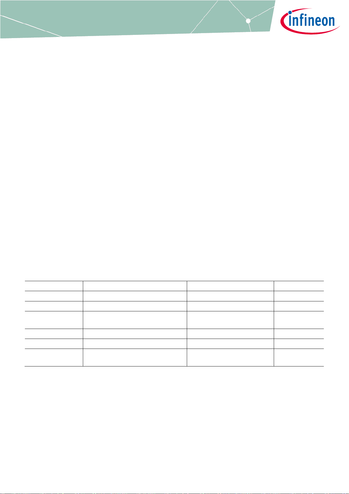
Product type
Application
Output Rating
R
DS(ON)
Typ
IMM101T-015M
Single Motor Control
500V / 1A
4.8 Ω
IMM101T-046M
Single Motor Control
600V / 4A
1.26 Ω
IMM101T-056M
Single Motor Control
600V / 4A (optimized for lowfrequency operation)
0.86 Ω
IMM102T-015M
Single Motor Control + Boost PFC
500V / 1A
4.8 Ω
IMM102T-046M
Single Motor Control + Boost PFC
600V / 4A
1.26 Ω
IMM102T-056M
Single Motor Control + Boost PFC
600V / 4A (optimized for lowfrequency operation)
0.86 Ω

Datasheet 4-24-2020 V1.2
IMM100 series - iMOTION™ Smart IPM for motor control
Fully integrated high performance motor control system
Table of Contents
Table of Contents
iMOTION™ IMM101T/IMM102T - Smart IPM for motor control .......................................... 1
Feature list ................................................................................................................. 1
Applications ................................................................................................................ 1
IMM100 series description ............................................................................................ 2
Ordering information .................................................................................................. 2
Table of Contents ........................................................................................................ 3
1 Overview ..................................................................................................... 5
1.1 IMM100T – Motion Control Engine .......................................................................................................... 5
1.2 Gate Driver ............................................................................................................................................... 5
1.3 Switches ................................................................................................................................................... 5
1.4 Application Diagrams .............................................................................................................................. 6
1.5 IMM100T Application Use Cases ............................................................................................................. 7
1.5.1 Sensorless Single-Shunt .................................................................................................................... 7
1.5.2 Sensorless Leg Shunts ....................................................................................................................... 8
1.5.3 Configuration with 2 Hall Sensors ..................................................................................................... 9
1.5.4 Sensorless single-shunt with boost PFC ......................................................................................... 10
2 Pinout – IMM100T series .............................................................................. 11
3 Gate Driver Function ................................................................................... 13
3.1 Features and Protections ...................................................................................................................... 13
3.1.1 Integrated Bootstrap Functionality ................................................................................................. 13
3.1.2 Undervoltage Lockout Protection ................................................................................................... 14
3.2 Block Diagram ....................................................................................................................................... 15
4 DC Characteristics ...................................................................................... 16
4.1 Absolute Maximum Ratings .................................................................................................................. 16
4.2 Recommended Operating Conditions .................................................................................................. 17
4.3 Static Electrical Characteristic .............................................................................................................. 17
4.4 Dynamic Electric Characterisitic ........................................................................................................... 18
4.5 MOSFET Avalanche Characteristics ...................................................................................................... 19
4.6 Thermal Characteristics ........................................................................................................................ 19
4.7 Thermal Characterization ..................................................................................................................... 20
4.8 Power Consumption IMM100T series ................................................................................................... 23
4.9 Flash Memory Parameters .................................................................................................................... 24
4.10 Digital I/O DC Characteristics ................................................................................................................ 24
4.11 Analog I/O DC Characteristics ............................................................................................................... 25
4.12 Under Voltage Lockout DC characteristics ........................................................................................... 25
4.13 Analog to Digital Converter – IMM100T series ...................................................................................... 26
4.14 Temperature Sensor Characteristic ..................................................................................................... 26
5 AC Characteristics ....................................................................................... 27
5.1 Internal Oscillator AC Characteristics ................................................................................................... 27
5.2 Power-Up and Supply Threshold Characteristics ................................................................................ 28
5.3 Motor Control Parameters – IMM100T series ....................................................................................... 28
5.3.1 PWM Characteristics – IMM100T series ............................................................................................ 28
5.3.2 Fault timing – IMM100T series ......................................................................................................... 28
5.4 Power Factor Correction (PFC) parameters – IMM102T ....................................................................... 29

Datasheet 4-24-2020 V1.2
IMM100 series - iMOTION™ Smart IPM for motor control
Fully integrated high performance motor control system
Table of Contents
5.4.1 Boost PFC characteristics – IMM102T .............................................................................................. 29
5.5 Communication interface parameters – IMM100T series .................................................................... 29
5.5.1 UART interface - IMM100T series ..................................................................................................... 29
6 I/O Structure .............................................................................................. 30
7 Package Outline ......................................................................................... 31
8 Part Marking Information ............................................................................ 33
9 Quality Declaration ..................................................................................... 34
Revision history ........................................................................................................ 34

Datasheet 4-24-2020 V1.2
IMM100 series - iMOTION™ Smart IPM for motor control
Fully integrated high performance motor control system
Overview
1 Overview
IMM100T modules contain a processor core that can address the real-time control needs of motor control. It can
use low-cost single shunt or leg shunts as motor current feedback by a combination of on-chip hardware and
firmware. Complex FOC control algorithms either sensorless or with sensors, as well as system level control can
be easily implemented inside IC and meet fan, pump and compressor applications requirements.
A standby mode helps to decrease system power consumption when the motor is stopped. The high-voltage
level shifting function with boot strap diode function is integrated into the gate driver IC. The device also contains
the six low-loss 500V power FET or 650V CoolMOS which form the three phase inverter circuit.
1.1 IMM100T – Motion Control Engine
iMOTION™ IMM100T is the latest generation inverter including controller designed as a single package solution
for inverterized motor control applications with or without power factor correction. The IMM100T series provides
a built-in closed loop sensorless (or optionally sensor based) control algorithm using the unique flexible Motion
Control Engine (MCE) for permanent magnet motors. Infineon’s patented and field proven MCE implements field
oriented control (FOC) using single or leg shunt current feedback and uses space vector PWM with sinusoidal
signals to achieve highest energy efficiency. In addition to the motor control algorithm it also integrates multiple
protection features like over- and under-voltage, over current, rotor lock etc. The IMM100T series takes
advantage of a new hardware platform combining an ARM® Cortex® core with an innovative set of analog and
motor control peripherals. The high-level of integration in terms of hardware and software results in a minimum
number of external components required for the implementation of the inverter control.
The next generation of the MCE not only further improves the performance of the control algorithm but also adds
functionality like sensor support for accurate rotor positioning, ready-to-use PFC algorithm as well as more and
flexible and faster host interface options.
The IMM100T series is offered in several device variants ranging from single motor control to motor control plus
PFC. All devices can be used in applications requiring functional safety according to IEC 60335 (‘Class B’).
This data sheet provides all electrical, mechanical, thermal and quality parameters. A more detailed description
of the features and functionality can be found in the respective reference manual of the MCE software.
There are multiple versions of the MCE software offered from Infineon and made available via download from
the Infineon web site. By using a special secure boot algorithm it is assured that the MCE software versions can
only be installed onto the matching hardware derivative, i.e. IMM100T variants for which the software has been
tested and released. Infineon provides the tools to program these software images.
1.2 Gate Driver
The gate driver is designed to work with MCE within an integrated power module. It has integrated boot strap
bootFET structure, only external bootstrap capacitors are needed outside the module. The gate driver includes
an under voltage protection and a fault reporting system. The gate driver is based on 600V High-Voltage Junction
Isolation technology.
1.3 Switches
The IMM100T modules are available in three different power stage options
6 Ohm 500V Trench MOSFETs in versions IMM101T-015 and IMM102T-015
1.4 Ohm 650V CoolMOS™ in versions IMM101T-046 and IMM102T-046 (600V maximum voltage is defined
by gate driver technology)

Datasheet 4-24-2020 V1.2
IMM100 series - iMOTION™ Smart IPM for motor control
Fully integrated high performance motor control system
Overview
0.95 Ohm 650V CoolMOS™ in versions IMM101T-056 and IMM102T-056 (600V maximum voltage is defined
by gate driver technology)
1.4 Application Diagrams
VCC
VB3
U
Power
Supply
VSS1
pin 6
COM
VBUS
2K
Rs
VB2
VB1
V
W
VSS2
pin 36
VDD
JTAG
UART
Digita l I/O
AIN0/V bus
AIN1/V sp
Analog speed
control
UART
HIN1
HIN2
HIN3
LIN1
LIN2
LIN3
RFE
MCE
GATE
DRIVER
15V
3.3V
AIN2 wit h
Gain x3
220p
3.3V
10K
100
Figure 1 Application Block Diagram using IMM101T – Single Shunt Configuration
VCC
VB3
Power
Supply
VSS1
pin6
COM
VBUS
2K
VB2
VB1
VSS2
VDD
JTAG
UART
Digita l I/O
AIN10/ Vbus
AIN0/V sp
Analog speed
control
UART
HIN1
HIN2
HIN3
LIN1
LIN2
LIN3
RFE
MCE
GATE
DRIVER
15V
3.3V up to 5V
AIN9
2K
2K
220pF
3.3V
10K
3.3V
10K
3.3V
10K
100
100
AIN6
AIN2
220pF
100
220pF
100
RS1
RS2 RS3
Figure 2 Application Block Diagram using IMM101T – Leg Shunts Configuration

Datasheet 4-24-2020 V1.2
IMM100 series - iMOTION™ Smart IPM for motor control
Fully integrated high performance motor control system
Overview
1.5 IMM100T Application Use Cases
This chapter provides more details about most common application use cases for IMM100 series’ devices,
including necessary passive components and pin connections. For full information about each pin functionality,
refer to Table1.
1.5.1 Sensorless Single-Shunt
The sensorless single-shunt use case shown below is a most common application use case for IMM100 devices,
alowing lowest BOM cost and highest number of available programmable pins for system-level functions.
M
VSS
RXD0
TXD0
IS
Vbus
1M
1M
13.3k
Vbus sense
2K
Rs
10K
3.3V
Vsp
VrW
Vbus
VsU
VrU
VrV
VbW
VbV
Vss1
Vcc
P1.7
Vdd
P2.10
P2.9
P2.6
Vss2
P2.2
P2.0 / P4.6
P0.15
P0.14
VsU
VbU
VsV
VsW
P2.11 / P2.13
3.3V
VsV
VsW
C_REF
AIN2
15V
Vbus sense
AIN6
Options for Input Set Point:
1- Analog Input Vsp to pin34 P2.0
2- UART input through P0.14 and P0.15
3- Duty (PWM) or frequency input on pin34 P4.6
Other Pins available to the user:
P2.6, P2.2, P1.7
100
220pF
Figure 3 IMM101T Sensorless, single shunt configuration

Datasheet 4-24-2020 V1.2
IMM100 series - iMOTION™ Smart IPM for motor control
Fully integrated high performance motor control system
Overview
1.5.2 Sensorless Leg Shunts
The sensorless leg shunts configuration may be used in applications where only very low acoustic noise is
requrired.
M
VSS
RXD0
TXD0
Vbus
1M
1M
13.3k
Vbus sense
Vsp
3.3V
VsV
VsW
C_REF
15V
Rs1
I_Rs1
Rs2
I_Rs2
I_Rs3
Rs3
IW
IU
I_RS3
IV
Vbus sense
Options for Input Set Point:
1- Analog Input Vsp to pin34 P2.0
2- UART input through P0.14 and P0.15
3- Duty (PWM) or frequency input on pin34 P4.6
Other Pins available to the user:
P1.7
If only two shunts are used, P2.2 is available
VrW
Vbus
VsU
VrU
VrV
VbW
VbV
Vss1
Vcc
P1.7
Vdd
P2.10
P2.9
P2.6
Vss2
P2.2
P2.0 / P4.6
P0.15
P0.14
VsU
VbU
VsV
VsW
P2.11 / P2.13
2K
10K
3.3V
100
220pF
I_RS2
2K
10K
3.3V
100
I_RS1
2K
10K
3.3V
100
220pF
220pF
Figure 4 IMM101T Sensorless, three leg shunts configuration

Datasheet 4-24-2020 V1.2
IMM100 series - iMOTION™ Smart IPM for motor control
Fully integrated high performance motor control system
Overview
1.5.3 Configuration with 2 Hall Sensors
Options for Input Set Point:
1- Analog Input Vsp to pin34 P2.0
2- UART input through P0.14 and P0.15
3- Duty (PWM) or frequency input on pin 34 P4.6
Other Pins available to the user:
P1.7
If DcBus is not measured, P2.10 is
available
M
VSS
RXD0
TXD0
IS
Vbus
1M
1M
13.3k
Vbus sense
2K
Rs
10K
3.3V
Vsp
VrW
Vbus
VsU
VrU
VrV
VbW
VbV
Vss1
Vcc
P1.7
Vdd
P2.10
P2.9
P2.6
Vss2
P2.2
P2.0 / P4.6
P0.15
P0.14
VsU
VbU
VsV
VsW
P2.11 / P2.13
3.3V
VsV
VsW
C_REF
15V
Vbus
sense
100
220pF
H0
3.3V
1.2k
3.3V
1nF
H1
3.3V
1.2k
3.3V
1nF
Figure 5 IMM101T Two Hall sensors, single shunt configuration

Datasheet 4-24-2020 V1.2
IMM100 series - iMOTION™ Smart IPM for motor control
Fully integrated high performance motor control system
Overview
1.5.4 Sensorless single-shunt with boost PFC
M
RXD0
TXD0
IS
Vbus
1M
1M
13.3k
Vbus sense
Rs
VrW
Vbus
VsU
VrU
VrV
VbW
VbV
Vss1
Vcc
P1.7
Vdd
P2.10
P2.9
P2.6
Vss2
P2.2
P2.0 / P4.6
P0.15
P0.14
VsU
VbU
VsV
VsW
P2.11 / P2.13
3.3V
VsV
VsW
C_REF
IPFC
15V
Vbus sense
Options for Input Set Point:
UART input through P0.14 and P0.15
PFCG
PFC
gate
driver
VSS
Rpfc
PFC Shunt
PFCG
AC line ~
1M
1M
15k
1M
1M
15k
VAC+ VAC-
VAC+
VAC-
15V
0.47k
12k
3.3V
100
100
1.0
220p
5K
12k
3.3V
1k
PFC Shunt
1n
Figure 6 IMM102T Sensorless Single shunt with Boost PFC function
Datasheet 4-24-2020 V1.2
IMM100 series - iMOTION™ Smart IPM for motor control
Fully integrated high performance motor control system
Pinout – IMM100T series
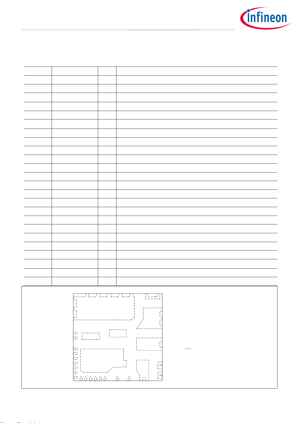
2 Pinout – IMM100T series
Table 1 Pinout description IMM101T series – single motor control – typical configuration
Pin
Name
Type
Description
1
Vbus scaled
I
Vbus scaled ADC input
2
CREF
I/O
Analog Overcurrent Comparator threshold DAC
3
VDD
P
Digital VDD input [3.3V – 5.0V]
4
P1.7
I/O
Digital Input --- Analog and Digital Output
5
Vcc
P
15V gate driver power supply input
6
VSS1
P
Gate Driver Power ground, connect externally via PCB to pin 36
7
VbV
P
V phase bootstrap capacitor positive
8
VbW
P
W phase bootstrap capacitor positive
9,10
VsU
P
U phase output
11,12
VrU
P
Leg U return – Low-Side MOS source
13,14
VrV
P
Leg V return – Low-Side MOS source
15,16, 40
VsV
P
V phase output and V phase bootstrap capacitor negative
17,18,19
VsW
P
W phase output and W phase bootstrap capacitor negative
20,21
VrW
P
Leg W return – Low-Side MOS source
22~29
Vbus
P
DC bus voltage
30, 39
VsU
P
U phase bootstrap capacitor negative
31
VbU
P
U phase bootstrap capacitor positive
32
RX0
I
Serial Port Receive input
33
TX0
O
Serial Port transmit output
34
Vsp/AIN 0
I
Analog Voltage Set Point Input
35
IW (or H0)/AIN 2
I
Analog Current sense input phase W or Hall0 input
36,41
VSS2
P
Signal ground --- Connect externally via PCB to pin 6
37
IV (or H1)/AIN 6
I
Analog Current sense input phase V or Hall1 input
38
ISS or IU
I
Analog Current sense input phase U or single Shunt
29
28
21 20
1
Top View
27
39
40
41
23 2225 2426
2 3 4 5 6 7 8
9 10
12
13
16
15
17
18
19
30
31
32
33
34
35
36
37
38
Note
Pins 39 and 40 are no t required
to be connected elect rically on
the PCB b ut are recomme nded
to be so ldered for mech anical
stability.
14
11
Figure 7 IMM100T series pinout

Datasheet 4-24-2020 V1.2
IMM100 series - iMOTION™ Smart IPM for motor control
Fully integrated high performance motor control system
Pinout – IMM100T series
Table 2 Pinout description IMM102T series – single motor + PFC – typical configuration
Pin
Name
Type
Description
1
Vbus scaled
I
Vbus scaled ADC input
2
CREF
I/O
Analog Overcurrent Comparator t hreshold DAC
3
VDD
P
Digital VDD input [3.3V – 5.0V]
4
PFCG
O
PWM Output to PFC gate driver
5
Vcc
P
15V gate driver power supply input
6
VSS1
P
Gate Driver Power ground, connect externally via PCB to pin 36
7
VbV
P
V phase bootstrap capacitor positive
8
VbW
P
W phase bootstrap capacitor positive
9,10
VsU
P
U phase output
11,12
VrU
P
Leg U return – Low-Side MOS source
13,14
VrV
P
Leg V return – Low-Side MOS source
15,16, 40
VsV
P
V phase output and V phase bootstrap capacitor negative
17,18,19
VsW
P
W phase output and W phase bootstrap capacitor negative
20,21
VrW
P
Leg W return – Low-Side MOS source
22~29
Vbus
P
DC bus voltage
30, 39
VsU
P
U phase bootstrap capacitor negative
31
VbU
P
U phase bootstrap capacitor positive
32
RX0
I
Serial Port Receive input
33
TX0
O
Serial Port transmit output
34
Vac+
I
Vac input ac+ voltage sensing through resistor external divider
35
Vac-
I
Vac input ac- voltage sensing through resistor external divider
36,41
VSS2
P
Signal ground --- Connect externally via PCB to pin 6
37
IPFC
I
Analog Current sense input PFC
38
ISS
I
Analog Current sense input single Shunt
Note: IMM101T and IMM102T share same package footprint.

Datasheet 4-24-2020 V1.2
IMM100 series - iMOTION™ Smart IPM for motor control
Fully integrated high performance motor control system
Gate Driver Function
3 Gate Driver Function
3.1 Features and Protections
The 3-phase high-voltage gate driver function is integrated in IMM100 series product. The driver output impedance
is designed to meet an optimal dv/dt for EMI and switching loss trade offs. It is designed for 5-6 V/nsec at a rated
current condition. The driver employs the anti-shoot-through protection, the integrated bootstrap function for
high-side floating supplies, the low standby power and the undervoltage lockout protection function for VCC and
high-side VBS supplies. The under voltage lockout for Vcc is reported as latched fault at pin RFE. The ITRIP
comparator between COM and VSS pin is disabled in IMM100. The gate driver block diagram is shown in Figure 10.
3.1.1 Integrated Bootstrap Functionality
The IMM100 series embeds an integrated bootstrap FET (BootFet) that allows an alternative drive of the bootstrap
supply for a wide range of applications. Each bootstrap FET is connected between the respective floating supply
VB (e.g. VBU, VBV and VBW, see page 15) and VCC:
Figure 8 Simplified BootFET connection
The bootstrap FET is suitable for most PWM modulation schemes, including trapezoidal control, and can be used
either in parallel with the external bootstrap network (diode+ resistor) or as a replacement of it. The use of the
integrated bootstrap FET as a replacement of the external bootstrap network may have some limitations at a very
high PWM duty cycle due to the bootstrap FET equivalent resistance (RBS, see page 17).
The integrated bootstrap FET is turned on during the time when LO is ‘high’ (e.g. LOU, LOV, LOW, see page 15), and
it has a limited source current due to RBS. The VBS voltage will be charged each cycle depending on the on-time of
LO and the value of the CBS capacitor, the drain-source drop of the MOSFET, and the low-side free-wheeling diode
drop.
The bootstrap FET follows the state of low-side output stage, the bootstrap FET is ON when LO is high, unless the
VB voltage is higher than approximately VCC. In that case, the bootstrap FET is designed to remain off until VB returns
below that threshold; this concept is illustrated in Figure 9.
Figure 9 Bootstrap FET timing diagram

Datasheet 4-24-2020 V1.2
IMM100 series - iMOTION™ Smart IPM for motor control
Fully integrated high performance motor control system
Gate Driver Function
3.1.2 Undervoltage Lockout Protection
This IC provides under-voltage lockout protection on both the VCC (logic and low-side circuitry) power supply and
the VBS (highside circuitry) power supply. Figure 10 is used to illustrate this concept; VCC (or VBS) is plotted over time
and as the waveform crosses the UVLO threshold (V
CCUV+/-
or V
BSUV+/-
) the under-voltage protection is enabled or
disabled.
Upon power-up, should the VCC voltage fail to reach the V
CCUV+
threshold, the IC will not turn-on. Additionally, if the
VCC voltage decreases below the V
CCUV-
threshold during operation, the under-voltage lockout circuitry will
recognize a fault condition and shutdown the high and low-side gate drive outputs.
Upon power-up, should the VBS voltage fail to reach the V
BSUV+
threshold, the IC will not turn-on. Additionally, if the
VBS voltage decreases below the V
BSUV-
threshold during operation, the under-voltage lockout circuitry will
recognize a fault condition, and shutdown the high-side gate drive outputs of the IC.
The UVLO protection ensures that the IC drives the external power devices only when the gate supply voltage is
sufficient to fully enhance the power devices. Without this feature, the gates of the external power switch could
be driven with a low voltage, resulting in the power switch conducting current while the channel impedance is
high; this could result in very high conduction losses within the power device and could lead to power device
failure. (V
CCUV+/-
and V
BSUV+/-
, see page 25)
Figure 10 UVLO protection

Datasheet 4-24-2020 V1.2
IMM100 series - iMOTION™ Smart IPM for motor control
Fully integrated high performance motor control system
Gate Driver Function
3.2 Block Diagram
Input
Noise
filter
Input
Noise
filter
Input
Noise
filter
Input
Noise
filter
Input
Noise
filter
Input
Noise
filter
Deadtime &
Shoot-Through
Prevention
Deadtime &
Shoot-Through
Prevention
Deadtime &
Shoot-Through
Prevention
HV Level
Shifter
VSS/COM
Level
Shifter
Latch
&
UV Detect
S
R
Driver
Integrated
BootFet
HV Level
Shifter
VSS/COM
Level
Shifter
Latch
&
UV Detect
S
R
Integrated
BootFet
HV Level
Shifter
VSS/COM
Level
Shifter
Latch
&
UV Detect
S
R
Driver
Integrated
BootFet
Driver
VSS/COM
Level
Shifter
VSS/COM
Level
Shifter
VSS/COM
Level
Shifter
Delay
Delay
Delay
Driver
Driver
Driver
PWM
L W
PWM
H W
PWM
L V
PWM
H V
PWM
H U
PWM
L U
VSS
VBW
HOW
VSW
VBV
HOV
VSV
VBU
HOU
VSU
VCC
LOW
LOV
LOU
COM
PWM
enable
H W
L W
H V
L V
H U
L U
VCC
UVLO
POR
RFE
Noise
filter
(500 ns)
VCC
EN
STBY
filter
(10us )
ITRIP LATCH
(set dominant)
S
R
Q
H
W
LU HU
LV HV
LW
EN
STAND-BY
Figure 11 Block diagram of gate driver function
Datasheet 4-24-2020 V1.2
IMM100 series - iMOTION™ Smart IPM for motor control
Fully integrated high performance motor control system
DC Characteristics
4 DC Characteristics
4.1 Absolute Maximum Ratings
Absolute maximum ratings indicate sustained limits beyond which damage to the module may occur. These are
not tested at manufacturing. All voltage parameters are absolute voltages referenced to VSS unless otherwise
stated in Table 2.
Table 2 Absolute Maximum Rating
Symbol
Description
Min
Max
Unit
BV
DSS
MOSFET Blocking Voltage
-015M
---
500
V
-046M and -056M
---
650
V
IO @TC=25°C
DC Output Current per MOSFET
-015M
--- 1 A
-046M and -056M
--- 4 A
IOP
Pulsed Output Current 1)
-015M
--- 6 A
-046M
---
8.2
A
-056M
---
11
A
PD @TC=25°C
Maximum Power Dissipation per
MOSFET 2)
-015M
---
11 W -046M
---
28.4
W
-056M
---
36.7
W
V
S U,V,W
Gate Driver High-Side Floating Supply Offset Voltage
V
B U,V,W
-20
V
B U,V,W
+0.3
V
V
B U,V,W
Gate Driver High-Side Floating Rated Voltage - 015
-0.3
600
V
Gate Driver High-Side Floating Rated Voltage - 046 --056
-0.3 600 V
VCC
Gate Driver Low-Side Supply Voltage
-0.3
20
V
BV
MODULE
Power Module Max Voltage -015M
---
500
V
Power Module Max Voltage -046M -056M
---
600
V
VDD
Digital IC Supply Voltage
-0.3 6 V
VID
Digital and Analog Pin Voltage
-0.3
VDD+0.3
V
TJ
Operating Junction Temperature - defined by
Controller technology
-40
115
°C
TL
Lead Temperature (Soldering, 30 seconds)
---
260
°C
TS
Storage Temperature
-40
125
°C
V
ISO
Isolation Voltage (1min)
---
1500
V
RMS
I
IN
Input current on any controller pin during overload
condition
-10 10 mA
ƩIIN
Absolute sum of all controller input currents during
overload condition
-50
50
mA
1)
Pulse Width=100µs, TC=25°C, Duty=1%.
2)
Single MOSFET in TO220 package at Tcase = 25°C
Note: Characterized, not tested at manufacturing.

Datasheet 4-24-2020 V1.2
IMM100 series - iMOTION™ Smart IPM for motor control
Fully integrated high performance motor control system
DC Characteristics
4.2 Recommended Operating Conditions
All voltage parameters are referenced to VSS.
Table 3 Recommended Operating Conditions
Symbol
Description
Min
Typ
Max
Unit
V
DCP
Positive DC Bus Input Voltage - 015
---
380
400
V
Positive DC Bus Input Voltage – 046 -- 056
---
400
480
V
V
B U,V,W
Gate Driver High-Side Floating Supply Voltage
VS+12
---
VS+18
V
VCC
Gate Driver Low-Side Supply Voltage
13.5
15.0
16.5
V
VDD
Digital IC Supply Voltage (3.3 V +/- 10%)
2.97
3.3
3.63
V
VDD
Digital IC Supply Voltage (5.0V +/- 10%)
4.5
5.0
5.5
V
MCLK
Master clock frequency
---
48.0
---
MHz
PCLK
Peripheral clock frequency
---
96.0
---
MHz
IOV
Input current on any port pin during overload
condition
-5
--5
mA
I
OVS
Absolute sum of all input circuit currents during
overload condition
---
--25
mA
Figure 12 Input Overload Current via ESD structures
4.3 Static Electrical Characteristic
Vcc=15 V, TA=25°C unless otherwhise specified.
Table 4 Static Electrical Characteristic
Symbol
Description
Min
Typ
Max
Units
I
LKH
@TJ=25°C,
VDS=500/650V
Leakage Current of
High-Side FETs in
Parallel
-015M
--- 1 ---
µA
-046M
--- 1 ---
-056M
--- 1 ---
I
LKL
@TJ=25°C,
VDS=500/650V
Leakage Current of
Low-Side FETs with
-015M
--- 4 ---
µA
-046M
--- 4 ---
-056M
--- 4 ---

Datasheet 4-24-2020 V1.2
IMM100 series - iMOTION™ Smart IPM for motor control
Fully integrated high performance motor control system
DC Characteristics
Symbol
Description
Min
Typ
Max
Units
Gate Drive IC in
Parallel
R
DS(ON)
@TJ=25°C,
VGS=10V,
ID=1.5A
Drain to Source ON
Resistance
-015M
---
4.8
6 Ω -046M
---
1.26
1.4
-056M
---
0.855
0.95
I
DSS
@TJ=25°C,
VDS=500/650
V, VGS=0 V
Zero Gate Voltage
Drain Current
-015M
---
---
1
µA
-046M
---
---
1
-056M
---
---
1
VSD @TJ=25 °C,
VGS=0 V, IF=0.5
A (-015M),
IF=1.5 A (046M), IF=2.2 A
(-056M)
MOSFET Diode
Forward Voltage Drop
-015M
---
0.8
--- V -046M
---
0.9
---
-056M
---
0.9
---
RBS
Bootstrap FET
Resistance
-015M
---
200
--- Ω -046M
---
200
---
-056M
---
200
---
Note: All values obtained during characterization, not tested at munfacturing.
4.4 Dynamic Electric Characterisitic
VCC=15 V, TA=25°C, all voltage parameters are referenced to VSS unless otherwise specified.
Table 5 Dynamic Electric Characteristic
Symbol
Description
Min
Typ
Max
Units
EON @TJ=25 °C,
V+=300 V, ID=0.5
A
Switching Energy,
Turn On Condition
-015M
---
27.2
---
µJ
-046M
---
36.6
---
-056M
---
44.4
---
E
OFF
@TJ=25 °C,
V+=300 V, ID=0.5
A
Switching Energy,
Turn Off Condition
-015M
---
2.00
---
µJ
-046M
---
1.97
---
-056M
---
2.53
---
E
REC
@TJ=25 °C,
V+=300 V, ID=0.5
A
Switching Energy,
Diode Reverse
Recovery
-015M
---
10.8
---
µJ
-046M
---
8.43
---
-056M
---
9.88
---
EON @TJ=115 °C,
V+=300 V, ID=0.5
A
Switching Energy,
Turn On Condition
-015M
---
31.8
---
µJ
-046M
---
49.7
---
-056M
---
59.7
---
E
OFF
@TJ=115
°C, V+=300 V,
ID=0.5 A
Switching Energy,
Turn Off Condition
-015M
---
1.96
---
µJ
-046M
---
1.81
---
-056M
---
2.27
---
-015M
---
12.6
---
µJ

Datasheet 4-24-2020 V1.2
IMM100 series - iMOTION™ Smart IPM for motor control
Fully integrated high performance motor control system
DC Characteristics
Symbol
Description
Min
Typ
Max
Units
E
REC
@TJ=115
°C, V+=300 V,
ID=0.5 A
Switching Energy,
Diode Reverse
Recovery
-046M
---
7.94
---
-056M
---
9.91
---
Note: All values obtained during characterization, not tested at munfacturing.
4.5 MOSFET Avalanche Characteristics
Table 6 MOSFET Avalanche Characteristic
Symbol
Description
Min
Typ
Max
Units
EAS, V+=100 V,
ID=1.7 A
Single Pulse
Avalanche Energy
-015M
---
---
49
mJ
EAS, V+=50 V,
ID=0.6 A
-046M
---
---
26
EAS, V+=50 V,
ID=1 A
-056M
---
---
50
Note: All values obtained during characterization, not tested at munfacturing.
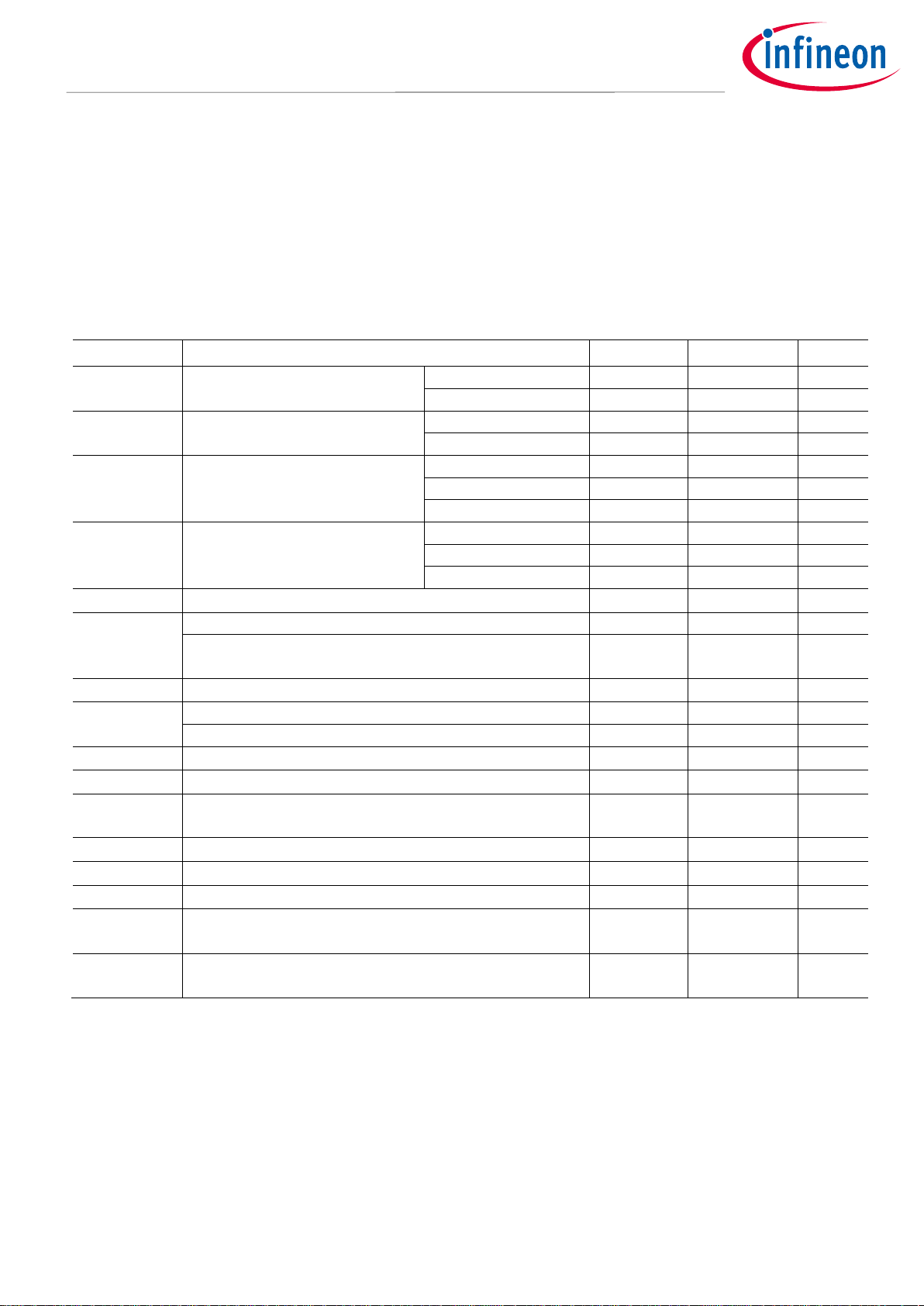
4.6 Thermal Characteristics
Table 7 Thermal Characteristics
Symbol
Description
Min
Typ
Max
Units
R
th(J-amb)
Total Thermal
Resistance Junction
to Ambient
---
27.7
---
°C/W
Note: All values obtained during characterization, not tested at munfacturing.
The previous value of R
th(J-amb)
has been obtained under the following testing condition: T
amb
=25°C, T
hotspot
=51.6°C
and a dissipated power of 1W. A FR4 PCB with 2oz copper has been used and the PCB layout is shown in Figure 13.
Figure 13 PCB layout used for thermal characterization: 2oz copper, 2 layers. DcBus Pad: 3,0 cm x 1,8 cm
on both layers with 144 vias.
Module

Datasheet 4-24-2020 V1.2
IMM100 series - iMOTION™ Smart IPM for motor control
Fully integrated high performance motor control system
DC Characteristics
4.7 Thermal Characterization
Figure 14, 15, 16, 17, 18, 19 show the thermal characterizations of the three part numbers. The tests reported in
Figure 14, 15, 16 have been performed under the following conditions: T
amb
=25°C, different phase current values
until the case reaches 105°C, two PWM frequencies (6 and 16kHz) and two different modulation types (3-phase
modulation and 2-phase flat bottom modulation). The tests reported in Figure 17, 18, 19 have been performed
under the following conditions: T
amb
=60°C, different phase current values until the case reaches 105°C, two PWM
frequencies (6 and 16kHz) and two different modulation type (3-phase modulation and 2-phase flat bottom
modulation). 2-ph flat bottom modulation allows the reduction of the switching losses compared with 3-phase
SVPWM (symmetrical placement of zero vectors). For the test with T
amb
=60°C, the 3-phase modulation has not
been used. For all the tests, the phase current has been limited to 600 mArms in order to avoid damage to the
motor used for the tests. A FR4 PCB with 2oz copper has been used and the PCB layout is shown in Figure 13.
Figure 14 IMM101T-015M Thermal Characterization, T
amb
=25°C, different phase current values until the
case reaches 105°C, FR4 PCB with 2oz copper
0
20
40
60
80
100
120
180.0 230.0 280.0 330.0 380.0
T
case
[°C]
Phase Current [mA
rms
]
IMM101T-015M, Thermal Characterization T
amb
=25°C
3-phase modulation 16kHz
2-phase modulation 16kHz
3-phase modulation 6kHz
2-phase modulation 6kHz

Datasheet 4-24-2020 V1.2
IMM100 series - iMOTION™ Smart IPM for motor control
Fully integrated high performance motor control system
DC Characteristics
Figure 15 IMM101T-046M Thermal Characterization, T
amb
=25°C, different phase current values until the
case reaches 105°C, FR4 PCB with 2oz copper
Figure 16 IMM101T-056M Thermal Characterization, T
amb
=25°C, different phase current values until the
case reaches 105°C, FR4 PCB with 2oz copper
0
20
40
60
80
100
120
180.0 230.0 280.0 330.0 380.0 430.0 480.0 530.0 580.0 630.0
T
case
[°C]
Phase Current [mA
rms
]
IMM101T-046M, Thermal Characterization T
amb
=25°C
3-phase modulation 16kHz
2-phase modulation 16kHz
3-phase modulation 6kHz
2-phase modulation 6kHz
0
20
40
60
80
100
120
180.0 230.0 280.0 330.0 380.0 430.0 480.0 530.0 580.0 630.0
T
case
[°C]
Phase Current [mA
rms
]
IMM101T-056M, Thermal Characterization T
amb
=25°C
3-phase modulation 16kHz
2-phase modulation 16kHz
3-phase modulation 6kHz
2-phase modulation 6kHz

Datasheet 4-24-2020 V1.2
IMM100 series - iMOTION™ Smart IPM for motor control
Fully integrated high performance motor control system
DC Characteristics
Figure 17 IMM101T-015M Thermal Characterization, T
amb
=60°C, different phase current values until the
case reaches 105°C, FR4 PCB with 2oz copper
Figure 18 IMM101T-046M Thermal Characterization, T
amb
=60°C, different phase current values until the
case reaches 105°C, FR4 PCB with 2oz copper
60
65
70
75
80
85
90
95
100
105
110
190.0 210.0 230.0 250.0 270.0 290.0 310.0 330.0
T
case
[°C]
Phase Current [mA
rms
]
IMM101T-015M, Thermal Characterization T
amb
=60°C
2-phase modulation 16 kHz
3-phase modulation 6 kHz
2-phase modulation 6 kHz
60
65
70
75
80
85
90
95
100
105
110
190.0 240.0 290.0 340.0 390.0 440.0 490.0 540.0 590.0
T
case
[°C]
Phase Current [mA
rms
]
IMM101T-046M, Thermal Characterization T
amb
=60°C
2-phase modulation 16 kHz
3-phase modulation 6 kHz
2-phase modulation 6 kHz

Datasheet 4-24-2020 V1.2
IMM100 series - iMOTION™ Smart IPM for motor control
Fully integrated high performance motor control system
DC Characteristics
Figure 19 IMM101T-056M Thermal Characterization, T
amb
=60°C, different phase current values until the
case reaches 105°C, FR4 PCB with 2oz copper
Note: Characterized, not tested at manufacturing.
4.8 Power Consumption IMM100T series
VCC=15V, VDD=5V, V
BUS
= 300V, Ta = 25˚C, unless specified otherwise.
Note: These parameters are not subject to production test, but verified by design and/or characterization.
Table 8 Power Consumption – IMM100T series
Symbol
Parameter
Min
Typ
Max
Unit
Condition
P
MOTOR
Power Consumption – motor
active and PFC not active
---
50
100
mW
P
MOTOR+PFC
Power Consumption – motor
and PFC active
---
70
100
mW
IMM102T only
I
DDPDS
Deep Sleep mode controller
current
---
0.27
---
mA
t
SSA
Controller Wake-up time from
Sleep to Active mode
---- 6 ---
Clock
cycles
t
DSA
Controller Wake-up time from
Deep Sleep to Active mode
---
290
---
µs
60
65
70
75
80
85
90
95
100
105
110
190.0 240.0 290.0 340.0 390.0 440.0 490.0 540.0 590.0
T
case
[°C]
Phase Current [mA
rms
]
IMM101T-56M, Thermal Characterization T
amb
=60°C
2-phase modulation 16 kHz
3-phase modulation 6 kHz
2-phase modulation 6 kHz

Datasheet 4-24-2020 V1.2
IMM100 series - iMOTION™ Smart IPM for motor control
Fully integrated high performance motor control system
DC Characteristics
4.9 Flash Memory Parameters
Note: These parameters are not subject to production test, but verified by design and/or characterization.
Table 9
Symbol
Parameter
Min
Typ
Max
Unit
Condition
t
RET
Data
Retention
Time
10
---
---
years
Max. 100
erase /
program
cycle
N
ECYC
Erase Cycles
---
---
5 x 10⁴
cycles
Sum of
pages and
sector erase
cycles
N
TECYC
Total Erase
Cycles
---
---
2 x 10⁶
cycles
4.10 Digital I/O DC Characteristics
VDD=3.3V, Ta = 25˚C, all voltage parameters are referenced to VSS unless specified otherwise.
Note: These parameters are not subject to production test, but verified by design and/or characterization.
Table 10 Digital I/O Charasteristics
Symbol
Parameter
Min
Typ
Max
Unit
Condition
V
ILPS
Input Low-Voltage on port pins
with std Hysteresis
---
---
0.19 x
VDD
V V
IHPS
Input High-Voltage on port pins
with std Hysteresis
0.7 x
VDD
---
--- V
V
ILPL
Input Low-Voltage on port pins
with large Hysteresis
---
---
0.08 x
VDD
V V
IHPL
Input High-Voltage on port pins
with Large Hysteresis
0.85 x
VDD
---
--- V
V
OLP
Output Low-Voltage on port pins
(with standard pads)
---
---
0.4 V IOL = 3.5 mA
V
OLP1
Output Low-Voltage on highcurrent pads
---
---
0.32
V
IOL = 10 mA
V
OHP
Output High-Voltage on port pins
(with standard pads)
VDD-0.4
---
--- V IOH = -2.5 mA
V
OHP1
Output High-Voltage on
high-current pads
VDD –
0.32
---
--- V IOH = -6 mA
IL
Input leakage current
-1
--- +1
μA
VO = 3.3V or 0V
IOL
Low-Level output current
---
--5
mA
VO = 0.4V
IOH
High-Level output current
---
---
-7
mA
VO = 2.4V
t
HCPR tHCPF
Rise/fall time on High-Current
Pad
---
--12
ns
50 pF
tR tF
Rise/fall time on std Pad
---
---
15
ns
50 pF

Datasheet 4-24-2020 V1.2
IMM100 series - iMOTION™ Smart IPM for motor control
Fully integrated high performance motor control system
DC Characteristics
Symbol
Parameter
Min
Typ
Max
Unit
Condition
CIO
Pin capacitance (digital
inputs/outputs)
---
--10
pF
I
PUP
Pull-up current on port pins
---
---
-50
µA
VIH,min
Pull-up current on port pins
-65
---
---
µA
VIL,max
I
PDP
Pull-down current on port pins
---
---
30
µA
VIL,max
Pull-down current on port pins
60
---
---
µA
VIH,min
VPO
Voltage on any pin during VDD
power off
---
---
0.3 V
4.11 Analog I/O DC Characteristics
VDD=3.3V, Ta = 25˚C, all voltage parameters are referenced to VSS unless specified otherwise.
Note: These parameters are not subject to production test, but verified by design and/or characterization.
Table 11 Analog I/O Charasteristics
Symbol
Parameter
Min
Typ
Max
Unit
Condition
CIN
Switched capacitance of analog
inputs
---
1.2 2 pF
Gain 1, 3
---
4.5 6 pF
Gain 6, 12
ADC
GAIN
ADC Configurable Gain
---
1 – 3 – 6 –
12
---
C
AINT
Total capacitance of
an analog input
---
---
10
pF
C
AREFT
Total capacitance of
reference input
---
---
10
pF
4.12 Under Voltage Lockout DC characteristics
Ta = 25˚C, all voltage parameters are referenced to VSS unless specified otherwise.
Note: These parameters are not subject to production test, but verified by design and/or characterization.
Table 12 Undervoltage Lockout DC Charasteristics
Symbol
Parameter
Min
Typ
Max
Unit
Condition
V
DDPBO
VDD Brownout reset voltage
1.55
1.62
1.75
V
V
DDPA
VDD voltage to ensure defined
pad states
---
1.0
---
V
t
SSW
Start-up time from power-on
reset
---
260
---
µs
t
BMI
BMI program time
---
8.25
---
ms
V
CCUV+
V
BSUV+
VCC and VBS supply undervoltage
positive going threshold - gate
driver
8.0
8.9
9.8
V
V
CCUV-
V
BSUV-
VCC and V
BS
supply undervoltage
negative going threshold - gate
driver
7.4
8.2
9.0
V

Datasheet 4-24-2020 V1.2
IMM100 series - iMOTION™ Smart IPM for motor control
Fully integrated high performance motor control system
DC Characteristics
V
CCUVH
V
BSUVH
V
CC
and V
BS
supply under voltage
hysteresis – gate driver
---
0.7
---
V
4.13 Analog to Digital Converter – IMM100T series
The following table shows the Analog to Digital Converter (ADC) characteristics. This specification applies to all
analog input as given in the pin configuration list.
Note: These parameters are not subject to production test, but verified by design and/or characterization.
Table 13 ADC Characteristics – IMM100T series
Symbol
Parameter
Min
Typ
Max
Unit
Condition
V
AIN
Analog input voltage range
Vss –
0.05
---
VDD +
0.05
V
t
sample
Sample Time
---
200
---
ns EN
RMS
RMS noise
---
1.5
---
LSB 12
EA
DNL
DNL error
---
+/- 2.0
---
LSB 12
EA
INL
INL error
---
+/- 4.0
---
LSB 12
EA
GAIN
Gain error with external
reference
---
+/- 0.5
---
%
EA
OFF
Offset error
---
+/- 8.0
---
mV
4.14 Temperature Sensor Characteristic
IMM101T and IMM102T have an internal temperature sensor that is used by MCE to linearly derate the power
consumption and protect the power section. The linear power derating function with temperature shutdown is
defined by parameters programmed by the user.
The power dissipation must be limited so that the average controller junction temperature does not exceed 115
°C.
Note: Temperature sensor characteristic is not subject to production test, but verified by design and/or
characterization.
Table 14 Temperature Sensor Characteristics
Symbol
Parameter
Min
Typ
Max
Unit
Condition
tM
Measurement time2)
---
---
10
ms TSR
Temperature sensor range
-40
---
115
°C
T
TSAL
Sensor Accuracy1)
-6
--- 6 °C
TJ > 20°C
-10
---
10
°C
0°C ≤ TJ ≤ 20°C
---
+/-8
---
°C
TJ < 0°C
1) The temperature sensor accuracy is independent of the supply voltage.
2) The temperature of the different parts of the IMM100 is strongly impacted by the thermal design of the
application and may be different from the temperature sensor reading. It is the designers’ responsibility
to always ensure that the maximum ratings given in this datasheet are never exceeded.

Datasheet 4-24-2020 V1.2
IMM100 series - iMOTION™ Smart IPM for motor control
Fully integrated high performance motor control system
AC Characteristics
5 AC Characteristics
5.1 Internal Oscillator AC Characteristics
VDD=3.3V, Ta = 25˚C unless specified otherwise.
Note: These parameters are not subject to production test, but verified by design and/or characterization.
Table 15 96MHz DCO1 Oscillator characteristics
Symbol
Parameter
Min
Typ
Max
Unit
Condition
f
NOM
CC
Nominal Frequency
-
96 - MHz
Δf
LTX
CC
-0.3 - +0.3
%
With respect to f
NOM
(typ),
Ta = -40 °C ~ 105 °C
Δf
LTTS
CC
Accuracy with adjustment
algorithm1) based on temperature
sensor
-0.6 - +0.6
%
With respect to f
NOM
(typ),
Ta = 0 °C ~ 105 °C
-1.9 - +1.0
%
With respect to f
NOM
(typ),
Ta = -25 °C ~ 105 °C
-2.6 - +1.3
%
With respect to f
NOM
(typ),
Ta = -40 °C ~ 105 °C
ΔfLT CC
Accuracy
-1.7 - +3.4
%
With respect to f
NOM
(typ),
Ta = 0 °C ~ 85 °C
-3.9 - +4.0
%
With respect to f
NOM
(typ),
Ta = -40 °C ~ 105 °C
1) MCE version newer or equal to V1.03.00, clock adjustment algorithm for improved accuracy enable.
Table 16 32kHz DCO2 Oscillator characteristics
Symbol
Parameter
Min
Typ
Max
Unit
Condition
f
NOM
CC
Nominal Frequency
32.5
32.75
33
MHz
ΔfST CC
Short term frequency deviation
(over VDD)
-1 - +1
%
With respect to f
NOM
(typ),
Ta = 25°C
ΔfLT CC
Accuracy
-1.7 - +3.4
%
With respect to f
NOM
(typ),
Ta = 0 °C ~ 85 °C
-3.9 - +4.0
%
With respect to f
NOM
(typ),
Ta = -40 °C ~ 105 °C
1) The deviation is related to the factory trimmed frequency at nominal VDD and Ta=+25C°
Under nominal conditions
after trimming
Accuracy with adjustment based
on XTAL as reference
Under nominal conditions1)
after trimming

Datasheet 4-24-2020 V1.2
IMM100 series - iMOTION™ Smart IPM for motor control
Fully integrated high performance motor control system
AC Characteristics
5.2 Power-Up and Supply Threshold Characteristics
The guard band between the lowest valid operating voltage and the brownout reset threshold provides a margin
for noise immunity and hysteresis. The electrical parameters may be violated while VDD is outside its operating
range. The brownout detection triggers a reset within the defined range. The prewarning detection can be used to
trigger an early warning and issue corrective and/or fail-safe actions in case of a critical supply voltage drop.
Note: These parameters are not subject to production test, but verified by design and/or characterization.
Note: Operating Conditions apply.
VDD=3.3V, Ta = 25˚C unless specified otherwise. C=100nF between VDD and VSS.
Table 17 Power-Up and Supply
Symbol
Parameter
Min
Typ
Max
Unit
Condition
t
RAMPUP
VDD ramp-up time
---
---
107
µs
S
VDDPOP
VDD slew rate
---
---
0.1
V/µs
Slope during normal
operation
S
VDDP10
---
---
10
V/µs
Slope during fast
transient within +/-10%
of VDD
S
VDDPrise
---
---
10
V/µs
Slope during power-on
or restart after
brownout event
S
VDDPfail
---
---
0.25
V/µs
Slope during supply
falling out of the +/-10%
limits
5.3 Motor Control Parameters – IMM100T series
Motion Control parameters that are defined in the iMOTION™ motion control engine (MCE) software are defined
and explained in iMOTION™ reference Manual.
5.3.1 PWM Characteristics – IMM100T series
Table 18 PWM timing in IMM100T
Symbol
Parameter
Min
Typ
Max
Unit
Condition
f
PWM
PWM frequency
5
16
40
kHz
5.3.2 Fault timing – IMM100T series
Table 19 Fault timing in IMM100T

Datasheet 4-24-2020 V1.2
IMM100 series - iMOTION™ Smart IPM for motor control
Fully integrated high performance motor control system
AC Characteristics
Symbol
Parameter
Min
Typ
Max
Unit
Condition
t
FLTwidth
Minimum pulse width of
fault event to be
acknowledged at input over
current comparators
1.0
---
---
µs
t
TRAP
reaction time to
acknowledged overcurrent
at input comparators –
Fault to PWM disable
propoagation time
---
1.3
---
µs
5.4 Power Factor Correction (PFC) parameters – IMM102T
The PFC parameters only refer to the IMM102T with integrated PFC control algorithm and are defined and
explained in iMOTION™ reference Manual.
5.4.1 Boost PFC characteristics – IMM102T
Table 20 PFC PWM timing in IMM102T
Symbol
Parameter
Min
Typ
Max
Unit
Condition
f
PFCPWM
PFC PWM frequency
---
20
70
kHz
5.5 Communication interface parameters – IMM100T series
The IMM100T series provides the following communication interfaces.
Note: These parameters are not subject to production test, but verified by design and/or characterization.
5.5.1 UART interface - IMM100T series
The UART interface is configured as given below.
Note: Operating Conditions apply.
Note: Each bit including start and stop bit is sampled three times at center of a bit at an interval of 1/16
T
BAUD
.
Table 21 UART timing in IMM100T - series
Symbol
Parameter
Min
Typ
Max
Unit
Condition
f
UART
UART baud rate
1200
57600
---
bps
UART mode
---
8-N-1
---
data-parity-stop
bit
t
UARTFIL
UART sampling filter period
---
1/16
---
T
BAUD
=1/f
UART

Datasheet 4-24-2020 V1.2
IMM100 series - iMOTION™ Smart IPM for motor control
Fully integrated high performance motor control system
I/O Structure
6 I/O Structure
The following figure shows the I/O structure for all digital I/O pins.
Figure 20 Digital I/O Structure
Figure 21 VCC pin I/O gate driver structure
ESD
Diode
ESD
Diode
V
CC
HIN,
LIN,
or EN
V
SS
R
PD
20 V
Clamp

Datasheet 4-24-2020 V1.2
IMM100 series - iMOTION™ Smart IPM for motor control
Fully integrated high performance motor control system
Package Outline
7 Package Outline
Figure 22 Bottom View, Dimensions in mm
Figure 23 Bottom View, Dimensions in mm

Datasheet 4-24-2020 V1.2
IMM100 series - iMOTION™ Smart IPM for motor control
Fully integrated high performance motor control system
Package Outline
Figure 24 Top View and Dimensions
Datasheet 4-24-2020 V1.2
IMM100 series - iMOTION™ Smart IPM for motor control
Fully integrated high performance motor control system
Part Marking Information
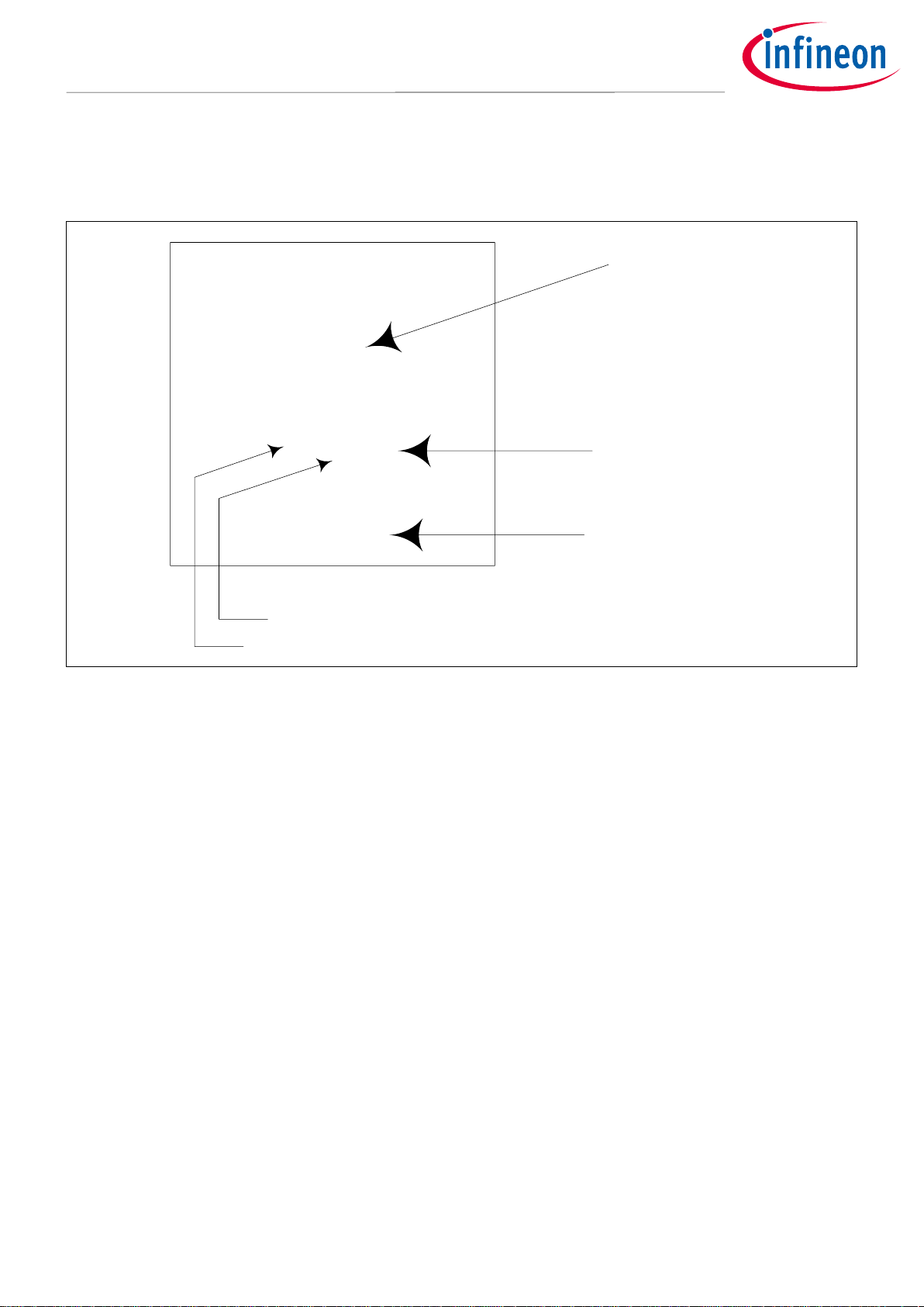
8 Part Marking Information
CYWW?
XXXXX
MCK099A
GYWW
XXXXXX
DATE CODE
ASSEMBLY SITE CODE
LOT CODE
MARKING CODE
IMM101T-046M
MARKING
PART NUMBER
Infineon
Figure 25 Part Marking

Datasheet 4-24-2020 V1.2
IMM100 series - iMOTION™ Smart IPM for motor control
Fully integrated high performance motor control system
Quality Declaration
9 Quality Declaration
Table 22 Quality Parameters
Qualification Level
Qualified for industrial applications according to
the relevant tests of JEDEC47/20/22
Moisture Sensitivity Level
MSL3
(per IPC/JEDEC J-STD-020C)
ESD
Charged Device Model
Class C2B
(per ANSI/ESDA/JEDEC standard JS -002)
Human Body Model
Class C2
(per EIA/JEDEC standard EIA/JESD22-A114-F)
RoHS Compliant
Yes
Note: Test condition for Temperature Cycling test is -40C to 125C.
Revision history
Document Version
Date of Release
Description of changes
v01_00
2019-04-10
Initial version
v01_01
2019-06-05
Typo Corrections
V01_02
2020-04-24
Revised oscillator accuracy specs. Changed max PWM frequency.

Edition 2019-06-05
Published by Infineon Technologies AG
81726 Munich, Germany
© 2019 Infineon Technologies AG All
Rights Reserved.
Do you have a question about any aspect
of this document?
Email: erratum@infineon.com
Document reference
IFX-vqf1553180223116
IMPORTANT NOTICE
The information given in this document shall in no event
be regarded as a guarantee of conditions or
characteristics (“Beschaffenheitsgarantie”).
With respect to any examples, hints or any typical values
stated herein and/or any information regarding the
application of the product, Infineon Technologies
hereby disclaims any and all warranties and liabilities of
any kind, including without limitation warranties of
non-infringement of intellectual property rights of any
third party.
In addition, any information given in this document is
subject to customer’s compliance with its obligations
stated in this document and any applicable legal
requirements, norms and standards concerning
customer’s products and any use of the product of
Infineon Technologies in customer’s applications.
The data contained in this document is exclusively
intended for technically trained staff. It is the
responsibility of customer’s technical departments to
evaluate the suitability of the product for the intended
application and the completeness of the product
information given in this document with respect to such
application.
WARNINGS
Due to technical requirements products may contain
dangerous substances. For information on the types in
question please contact your nearest Infineon
Technologies office.
Except as otherwise explicitly approved by Infineon
Technologies in a written document signed by
authorized representatives of Infineon Technologies,
Infineon Technologies’ products may not be used in any
applications where a failure of the product or any
consequences of the use thereof can reasonably be
expected to result in personal injury
Trademarks
All referenced product or service names and trademarks are the property of their respective owners.
 Loading...