

INFINEON IM69D120V01XTSA1 Datasheet

IM69D120
High performance digital XENSIVTM MEMS microphone
Description
The IM69D120 is designed for applications where low self-noise (high SNR), wide dynamic range, low distortions
and a high acoustic overload point is required.
Infineon's Dual Backplate MEMS technology is based on a miniaturized symmetrical microphone design, similar
as utilized in studio condenser microphones, and results in high linearity of the output signal within a dynamic
range of 95dB. The microphone distortion does not exceed 1% even at sound pressure levels of 118dBSPL. The
flat frequency response ( 28Hz low-frequency roll-o) and tight manufacturing tolerance result in close phase
matching of the microphones, which is important for multi-microphone (array) applications.
With its low equivalent noise floor of 25dBSPL (SNR 69dB(A)) the microphone is no longer the limiting factor in
the audio signal chain and enables higher performance of voice recognition algorithms.
The digital microphone ASIC contains an extremely low-noise preamplifier and a high-performance sigma-delta
ADC. Dierent power modes can be selected in order to suit specific current consumption requirements.
Each IM69D120 microphone is calibrated with an advanced Infineon calibration algorithm, resulting in small
sensitivity tolerances (± 1dB). The phase response is tightly matched (± 2°) between microphones, in order to
support beamforming applications.
Features
• Dynamic range of 95dB
- Signal to noise ratio of 69dB(A) SNR
- <1% total harmonic distortions up to
118dBSPL
- Acoustic overload point at 120dBSPL
• Sensitivity (± 1dB) and phase (± 2° @1kHz)
matched
• Flat frequency response with low frequency roll o
at 28Hz
Typical applications
• Devices with Voice User Interface (VUI)
- Smart speakers
- Home automation
- IOT devices
• Active Noise Cancellation (ANC) headphones and
earphones
• Very fast analog to digital conversion speed (6µs
latency @1kHz
• Power optimized modes determined by PDM
clock frequency
• Package dimensions: 4mm x 3mm x 1.2mm
• PDM output
• Omnidirectional pickup pattern
• High quality audio capturing
- Conference systems
- Cameras and camcorders
• Industrial or home monitoring with audio pattern
detection
Datasheet Please read the Important Notice and Warnings at the end of this document 1.0
www.infineon.com 2017-12-20
IM69D120
High performance digital XENSIVTM MEMS microphone
Use cases
Use cases
• Below 1% total harmonic distortion
- Voice command during music from the loud
speaker
- Eective active noise cancellation even close
to loud noise source
- Recordings in a discotheque or at a rock
concert
• High Signal to noise ratio
- Far field audio signal pick-up
- Low volume audio and whispered voice
capturing
- Microphone noise is no longer limiting the
audio chain
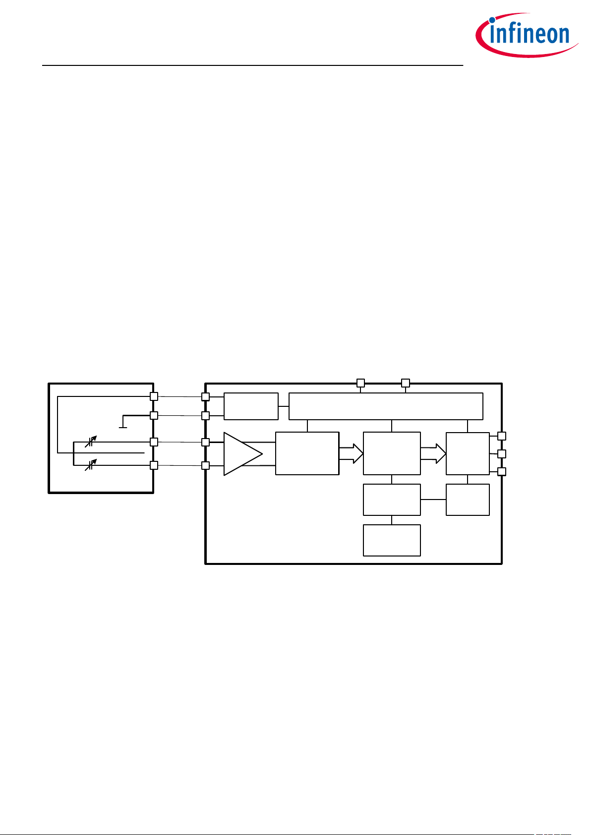
Block diagram
MEMS BIAS
CHARGE PUMP
• Sensitivity and phase matching
- Full utilization of voice algorithms capability
- Audio beam forming
- High and precise attenuation of background
noise
• Power optimized modes
- Low current consumption for always on
applications
- Long operating time of battery powered
devices
VDDGROUND
VOLTAGE REGULATORS
MEMS
BACKPLATE 1
MEMBRANE
BACKPLATE 2
AMP
ADC
DIGITAL SIGNAL
PROCESSING
DIGITAL CORE
CALIBRATION
COEFFICIENTS
1-BIT
PDM
INTERFACE
POWER
MODE
DETECTOR
ASIC
Figure 1 IM69D120 block diagram
Product validation
Technology qualified for industrial applications.
Ready for validation in industrial applications according to the relevant tests of IEC 60747 and 60749 or
alternatively JEDEC47/20/22.
DATA
SELECT
CLOCK
Datasheet 2 1.0
2017-12-20

IM69D120
High performance digital XENSIVTM MEMS microphone
Table of contents
Table of contents
Description . . . . . . . . . . . . . . . . . . . . . . . . . . . . . . . . . . . . . . . . . . . . . . . . . . . . . . . . . . . . . . . . . . . . . . . . . . . . .1
Features . . . . . . . . . . . . . . . . . . . . . . . . . . . . . . . . . . . . . . . . . . . . . . . . . . . . . . . . . . . . . . . . . . . . . . . . . . . . . . . 1
Typical applications . . . . . . . . . . . . . . . . . . . . . . . . . . . . . . . . . . . . . . . . . . . . . . . . . . . . . . . . . . . . . . . . . . . . 1
Use cases . . . . . . . . . . . . . . . . . . . . . . . . . . . . . . . . . . . . . . . . . . . . . . . . . . . . . . . . . . . . . . . . . . . . . . . . . . . . . . .2
Block diagram . . . . . . . . . . . . . . . . . . . . . . . . . . . . . . . . . . . . . . . . . . . . . . . . . . . . . . . . . . . . . . . . . . . . . . . . . . 2
Product validation . . . . . . . . . . . . . . . . . . . . . . . . . . . . . . . . . . . . . . . . . . . . . . . . . . . . . . . . . . . . . . . . . . . . . 2
Table of contents . . . . . . . . . . . . . . . . . . . . . . . . . . . . . . . . . . . . . . . . . . . . . . . . . . . . . . . . . . . . . . . . . . . . . . . 3
1 Typical performance characterstics . . . . . . . . . . . . . . . . . . . . . . . . . . . . . . . . . . . . . . . . . . . . . . . . . . . . . .4
2 Acoustic characteristics . . . . . . . . . . . . . . . . . . . . . . . . . . . . . . . . . . . . . . . . . . . . . . . . . . . . . . . . . . . . . . . . .5
2.1 Free field frequency response . . . . . . . . . . . . . . . . . . . . . . . . . . . . . . . . . . . . . . . . . . . . . . . . . . . . . . . . . . . . .6
3 Electrical parameters and characteristics . . . . . . . . . . . . . . . . . . . . . . . . . . . . . . . . . . . . . . . . . . . . . . . .7
3.1 Absolute maximum ratings . . . . . . . . . . . . . . . . . . . . . . . . . . . . . . . . . . . . . . . . . . . . . . . . . . . . . . . . . . . . . . . 7
3.2 Electrical parameters . . . . . . . . . . . . . . . . . . . . . . . . . . . . . . . . . . . . . . . . . . . . . . . . . . . . . . . . . . . . . . . . . . . . 7
3.3 Electrical characteristics . . . . . . . . . . . . . . . . . . . . . . . . . . . . . . . . . . . . . . . . . . . . . . . . . . . . . . . . . . . . . . . . . 8
4 Typical stereo application circuit . . . . . . . . . . . . . . . . . . . . . . . . . . . . . . . . . . . . . . . . . . . . . . . . . . . . . . .10
5 Reliability specifications . . . . . . . . . . . . . . . . . . . . . . . . . . . . . . . . . . . . . . . . . . . . . . . . . . . . . . . . . . . . . . .11
6 Package information . . . . . . . . . . . . . . . . . . . . . . . . . . . . . . . . . . . . . . . . . . . . . . . . . . . . . . . . . . . . . . . . . . 12
7 Footprint and stencil recommendation . . . . . . . . . . . . . . . . . . . . . . . . . . . . . . . . . . . . . . . . . . . . . . . . . 13
8 Packing . . . . . . . . . . . . . . . . . . . . . . . . . . . . . . . . . . . . . . . . . . . . . . . . . . . . . . . . . . . . . . . . . . . . . . . . . . . . . . . 14
Revision history . . . . . . . . . . . . . . . . . . . . . . . . . . . . . . . . . . . . . . . . . . . . . . . . . . . . . . . . . . . . . . . . . . . . . . . 15
Disclaimer . . . . . . . . . . . . . . . . . . . . . . . . . . . . . . . . . . . . . . . . . . . . . . . . . . . . . . . . . . . . . . . . . . . . . . . . . . . . 16
Datasheet 3 1.0
2017-12-20
IM69D120
High performance digital XENSIVTM MEMS microphone
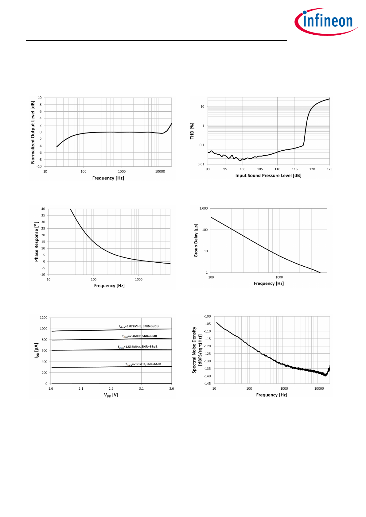
Typical performance characterstics
1 Typical performance characterstics
Test conditions: VDD = 1.8V, f
= 3.072MHz, no load on DATA
CLK
Figure 2 Typical freefield frequency response
Figure 3 Typical THD vs SPL
Figure 4 Typical phase response vs frequency
Figure 6 Typical IDD vs V
DD
Figure 5 Typical group delay vs frequency
Figure 7 Typical noise floor (unweighted)
Datasheet 4 1.0
2017-12-20
IM69D120
High performance digital XENSIVTM MEMS microphone
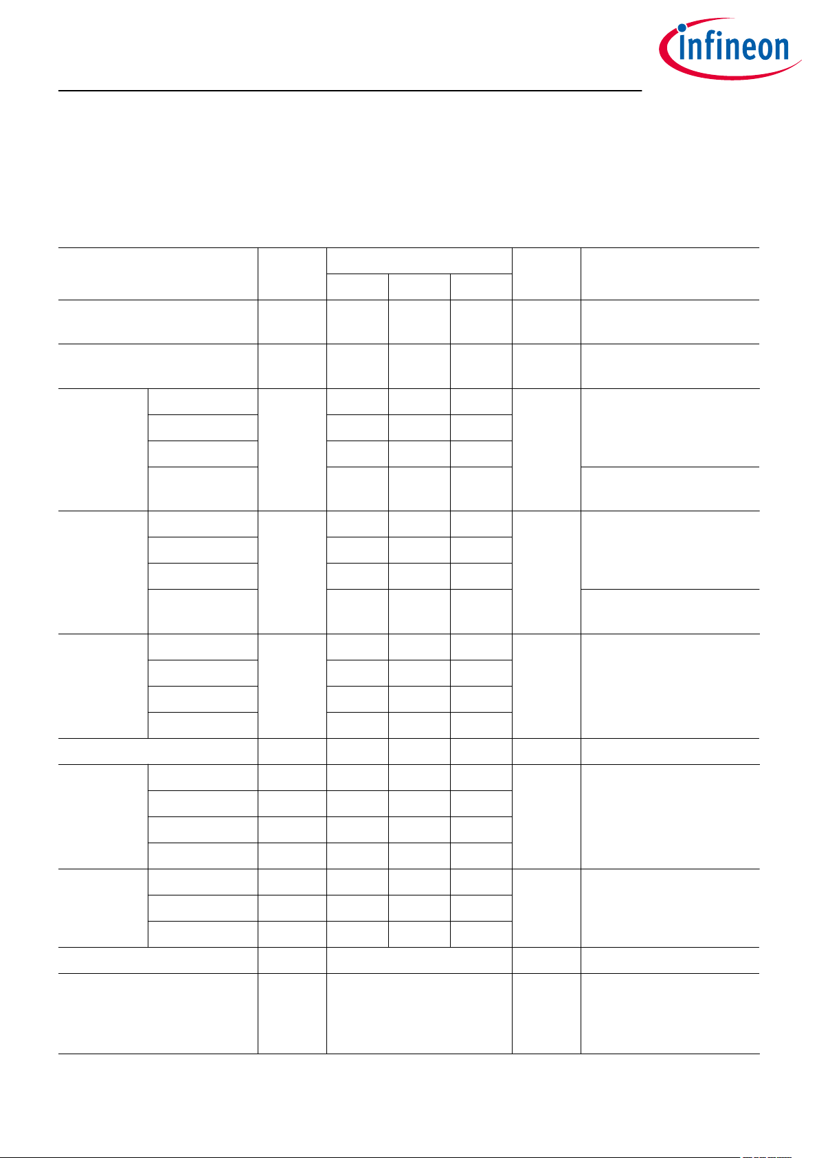
Acoustic characteristics
2 Acoustic characteristics
Test conditions ( unless otherwise specified in the table): VDD = 1.8V, f
bandwidth 20Hz to 20kHz, select pin grounded, no load on DATA, T
= 3.072MHz, TA = 25°C, 55% R.H., audio
CLK
= 9ns
edge
Table 1 IM69D130 acoustic specifications
Parameter Symbol Values Unit Note or Test condition
Min. Typ. Max.
Sensitivity -27 -26 -25 dBFS 1kHz, 94 dBSPL, all
operating modes
Acoustic Overload Point AOP 120 dBSPL THD = 10%, all operating
modes
Signal to
Noise Ratio
f
=3.072MHz SNR 69 dB(A) A-Weighted
clock
f
=2.4MHz 68
clock
f
=1.536MHz 66
clock
f
=768kHz 64 20Hz to 8kHz bandwidth,
clock
A-Weighted
Noise Floor f
=3.072MHz -95 dBFS(A) A-Weighted
clock
f
=2.4MHz -94
clock
f
=1.536MHz -92
clock
f
=768kHz -90 20Hz to 8kHz bandwidth,
clock
A-Weighted
Total
Harmonic
Distortion
94dBSPL THD 0.5 % Measuring 2nd to 5th
118dBSPL 1.0
harmonics; 1kHz, all
operating modes
119dBSPL 2.0
120dBSPL 10.0
Low Frequency Cuto Point f
C LP
28 Hz -3dB point relative to 1kHz
Group Delay 250Hz 70 µs
600Hz 15
1kHz 6
4kHz 1
Phase
Response
75Hz 19 °
1kHz 2
3kHz -1
Directivity Omnidirectional Pickup pattern
Polarity Positive pressure increases
density of 1's, negative
pressure decreases density
of 1's in data output
Datasheet 5 1.0
2017-12-20
 Loading...