

INFINEON HYB39S256400DT-6, HYB39S256400DT-7, HYB39S256400DT-7.5, HYB39S256400DT-8, HYB39S256800DT-6 User Manual
...
查询HYB39S256160DC-6供应商查询HYB39S256160DC-6供应商
Data Sheet, Rev. 1.02, Feb. 2004
HYB39S256400D[C/T](L)
HYB39S256800D[C/T](L)
HYB39S256160D[C/T](L)
256-MBit Synchronous DRAM
SDRAM
Memory Products
Never stop thinking.

Edition 2004-02
Published by Infineon Technologies AG,
St.-Martin-Strasse 53,
81669 München, Germany
© Infineon Technologies AG 2004.
All Rights Reserved.
Attention please!
The information herein is given to describe certain components and shall not be considered as a guarantee of
characteristics.
Terms of delivery and rights to technical change reserved.
We hereby disclaim an y and all war ranties , including b ut not limited to w arranties of non -infringement, regarding
circuits, descriptions and charts stated herein.
Infineon Technologies is an appro ved CECC manufacturer.
Information
For further information on technology, delivery terms and conditions and prices please contact your nearest
Infineon Technologies Office in Germany or our Infineon Technologies Representatives worldwide
(www.infineon.com).
Warnings
Due to technical requirements components may contain dangerous substances. For in formation on the types in
question please contact your nearest Infineon Technologies Office.
Infineon Technologies Components ma y only be used in lif e-support devices or systems with the e xpress written
approval of Infineon Technologies, if a failure of such components can reasonably be expected to cause the
failure of that life-support device or system, or to affect the safety or effectiveness of that device or system. Life
support devices or systems are intended to be implanted in the human body, or to support and/or maintain and
sustain and/or protect human life. If they fail, it is reasonable to assume that the health of the user or other
persons may be endangered.

Data Sheet, Rev. 1.02, Feb. 2004
Data Sheet, Rev. 1.02, Feb. 2004
HYB39S256400D[C/T](L)
HYB39S256800D[C/T](L)
HYB39S256160D[C/T](L)
256-MBit Synchronous DRAM
SDRAM
Memory Products
Memory Products
Never stop thinking.

HYB39S256[40/80/16]0D[C/T](L)
Revision History: Rev. 1.02 2004-02
Page Subjects (major changes since last revision)
17 Corrected Mode Register Definition in chapter 3
all Various layout and editorial changes
Previous Version: Rev. 1.01 2004-01
all Various layout and editorial changes
Previous Version: Rev. 1.0 2002-06
We Listen to Your Comments
Any information within this document that you feel is wrong, unclear or missing at all?
Your feedback will help us to continuously improve the quality of this document.
Please send your proposal (including a reference to this do cument) to:
techdoc.mp@infineon.com
Template: mp_a4_v2.0_2003-06-06.fm

HYB39S256[40/80/16]0D[C/T](L)
256-MBit Synchronous DRAM
Table of Contents Page
1 Overview . . . . . . . . . . . . . . . . . . . . . . . . . . . . . . . . . . . . . . . . . . . . . . . . . . . . . . . . . . . . . . . . . . . . . . . 6
1.1 Features . . . . . . . . . . . . . . . . . . . . . . . . . . . . . . . . . . . . . . . . . . . . . . . . . . . . . . . . . . . . . . . . . . . . . . . . 6
1.2 Description . . . . . . . . . . . . . . . . . . . . . . . . . . . . . . . . . . . . . . . . . . . . . . . . . . . . . . . . . . . . . . . . . . . . . . 6
2 Pin Configuration . . . . . . . . . . . . . . . . . . . . . . . . . . . . . . . . . . . . . . . . . . . . . . . . . . . . . . . . . . . . . . . . 8
2.1 Signal Pin Description . . . . . . . . . . . . . . . . . . . . . . . . . . . . . . . . . . . . . . . . . . . . . . . . . . . . . . . . . . . . . . 8
2.2 Package P–TSOPII–54 . . . . . . . . . . . . . . . . . . . . . . . . . . . . . . . . . . . . . . . . . . . . . . . . . . . . . . . . . . . . . 9
2.3 Package P–TFBGA–54 . . . . . . . . . . . . . . . . . . . . . . . . . . . . . . . . . . . . . . . . . . . . . . . . . . . . . . . . . . . 10
2.4 Block Diagrams . . . . . . . . . . . . . . . . . . . . . . . . . . . . . . . . . . . . . . . . . . . . . . . . . . . . . . . . . . . . . . . . . . 11
3 Functional Description . . . . . . . . . . . . . . . . . . . . . . . . . . . . . . . . . . . . . . . . . . . . . . . . . . . . . . . . . . . 14
3.1 Operation Definition . . . . . . . . . . . . . . . . . . . . . . . . . . . . . . . . . . . . . . . . . . . . . . . . . . . . . . . . . . . . . . 14
3.2 Initialization . . . . . . . . . . . . . . . . . . . . . . . . . . . . . . . . . . . . . . . . . . . . . . . . . . . . . . . . . . . . . . . . . . . . . 15
3.3 Mode Register Definition . . . . . . . . . . . . . . . . . . . . . . . . . . . . . . . . . . . . . . . . . . . . . . . . . . . . . . . . . . 15
3.3.1 Burst Length . . . . . . . . . . . . . . . . . . . . . . . . . . . . . . . . . . . . . . . . . . . . . . . . . . . . . . . . . . . . . . . . . . 17
3.4 Commands . . . . . . . . . . . . . . . . . . . . . . . . . . . . . . . . . . . . . . . . . . . . . . . . . . . . . . . . . . . . . . . . . . . . . 17
3.5 Operations . . . . . . . . . . . . . . . . . . . . . . . . . . . . . . . . . . . . . . . . . . . . . . . . . . . . . . . . . . . . . . . . . . . . . 18
3.5.1 Read and Write . . . . . . . . . . . . . . . . . . . . . . . . . . . . . . . . . . . . . . . . . . . . . . . . . . . . . . . . . . . . . . . . 18
3.5.2 DQM Function . . . . . . . . . . . . . . . . . . . . . . . . . . . . . . . . . . . . . . . . . . . . . . . . . . . . . . . . . . . . . . . . . 19
3.5.3 Suspend Mode . . . . . . . . . . . . . . . . . . . . . . . . . . . . . . . . . . . . . . . . . . . . . . . . . . . . . . . . . . . . . . . . . 19
3.5.4 Power Down . . . . . . . . . . . . . . . . . . . . . . . . . . . . . . . . . . . . . . . . . . . . . . . . . . . . . . . . . . . . . . . . . . 19
4 Electrical Characteristics . . . . . . . . . . . . . . . . . . . . . . . . . . . . . . . . . . . . . . . . . . . . . . . . . . . . . . . . . 20
4.1 Operating Conditions . . . . . . . . . . . . . . . . . . . . . . . . . . . . . . . . . . . . . . . . . . . . . . . . . . . . . . . . . . . . . 20
4.2 AC Characteristics . . . . . . . . . . . . . . . . . . . . . . . . . . . . . . . . . . . . . . . . . . . . . . . . . . . . . . . . . . . . . . . 23
5 Package Outlines . . . . . . . . . . . . . . . . . . . . . . . . . . . . . . . . . . . . . . . . . . . . . . . . . . . . . . . . . . . . . . . 26
Data Sheet 5 Rev. 1.02, 2004-02
HYB39S256[40/80/16]0D[C/T](L)
256-MBit Synchronous DRAM
1Overview
1.1 Features
• Fully Synchronous to Positive Clock Edge
• 0 to 70 °C operating temperature
• Four Banks controlled by BA0 & BA1
• Programmable CAS
• Programmable Wrap Sequence: Sequential or Interleave
• Programmable Burst Length: 1, 2, 4, 8 and full page
• Multiple Burst Read with Single Write Operation
• Automatic and Controlled Precharge Command
• Data Mask for Read / Write control (x4, x8)
• Data Mask for byte control (x16)
• Auto Refresh (CBR) and Self Refresh
• Power Down and Clock Suspend Mode
• 8192 refresh cycles / 64 ms (7,8 µs)
• Random Column Address every CLK (1-N Rule)
• Single 3.3 V
• LVTTL Interface versions
• Plastic Packages: P–TSOPII–54 400mil width (x4, x8, x16)
• Chipsize Packages: P–TFBGA–54 (12 mm x 8 mm)
± 0.3 V Power Supply
Latency: 2 & 3
Overview
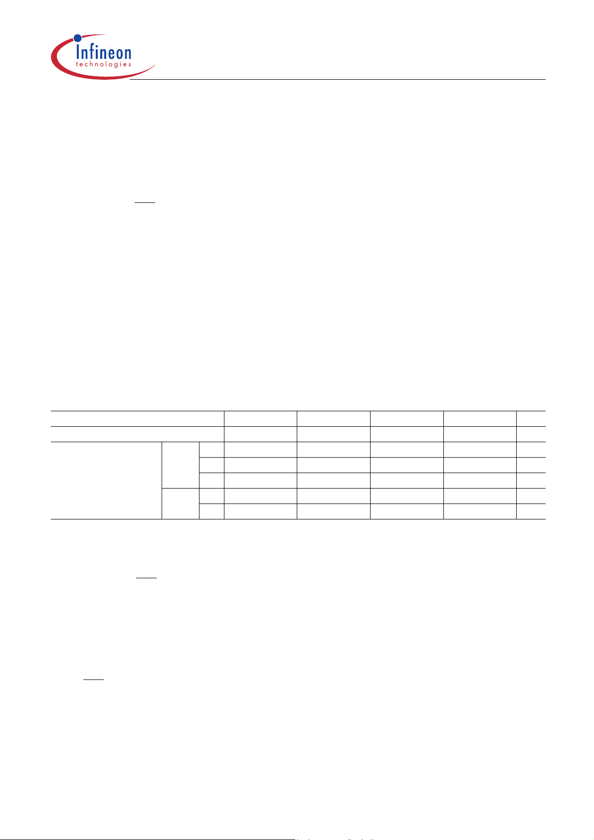
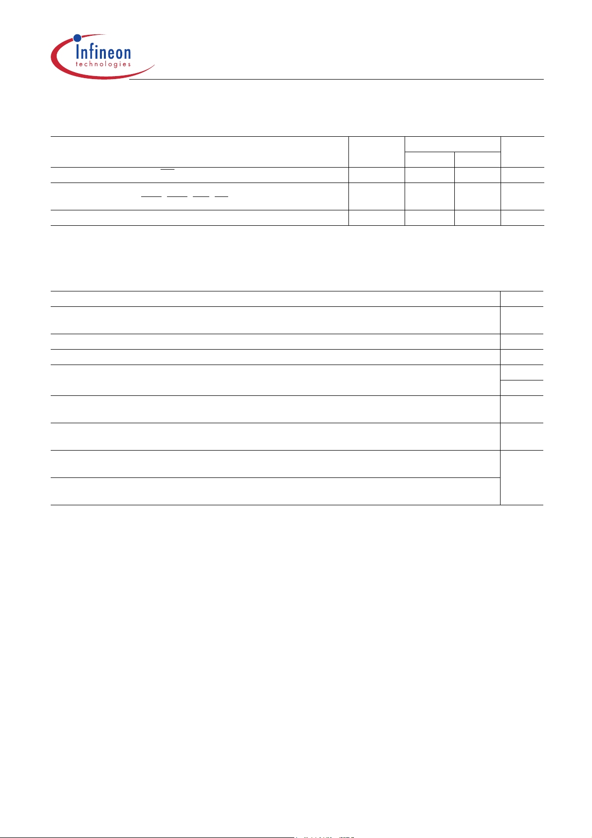
Table 1 Performance
Part Number Speed Code –6–7-7.5–8Unit
Speed Grade PC166 3–3–3 PC133 2–2–2 PC133 3–3–3 PC100 2–2–2 —
max. Clock Frequency @CL3
@CL2
f
166 143 133 125 MHz
CK3
t
677.58ns
CK3
t
5 5.4 5.4 6 ns
AC3
t
7.5 7.5 10 10 ns
CK2
t
5.4 5.4 6 6 ns
AC2
1.2 Description
The HYB39S256[40/80/16]0D[C/T](L) are four bank Synchronous DRAM’s organized as 4 banks x 16 MBit x4,
4 banks x 8 MBit x8 and 4 banks x 4 Mbit x16 respectively. These synchronous devices achieve high speed data
transfer rates for CAS
synchronizes the output data to a system clock. The chip is fabricated with INFINEON’s advanced 0.14 µm
256-MBit DRAM process technology.
The device is designed to comply with all industry standards set for synchronous DRAM products, both e lectrically
and mechanically. All of the contro l, address, data input and output circuits are synchronized with the positive edge
of an externally supplied clock.
Operating the four memory banks in an interleave fashion allows random access operation to occur at a higher
rate than is possible with standard DRAMs. A sequential and gapless data rate is possible depending on burst
length, CAS
Auto Refresh (CBR) and Self Refresh opera tion are supporte d. These d evices opera te with a single 3.3V
power supply. All 256-Mbit components are available in P–TSOPII–54 and P–TFBGA–54 packages.
latency and speed grade of the device.
-latencies by employing a chip architecture that prefetches multiple bits and then
± 0.3 V
Data Sheet 6 Rev. 1.02, 2004-02
10072003-13LE-FGQQ
HYB39S256[40/80/16]0D[C/T](L)
256-MBit Synchronous DRAM
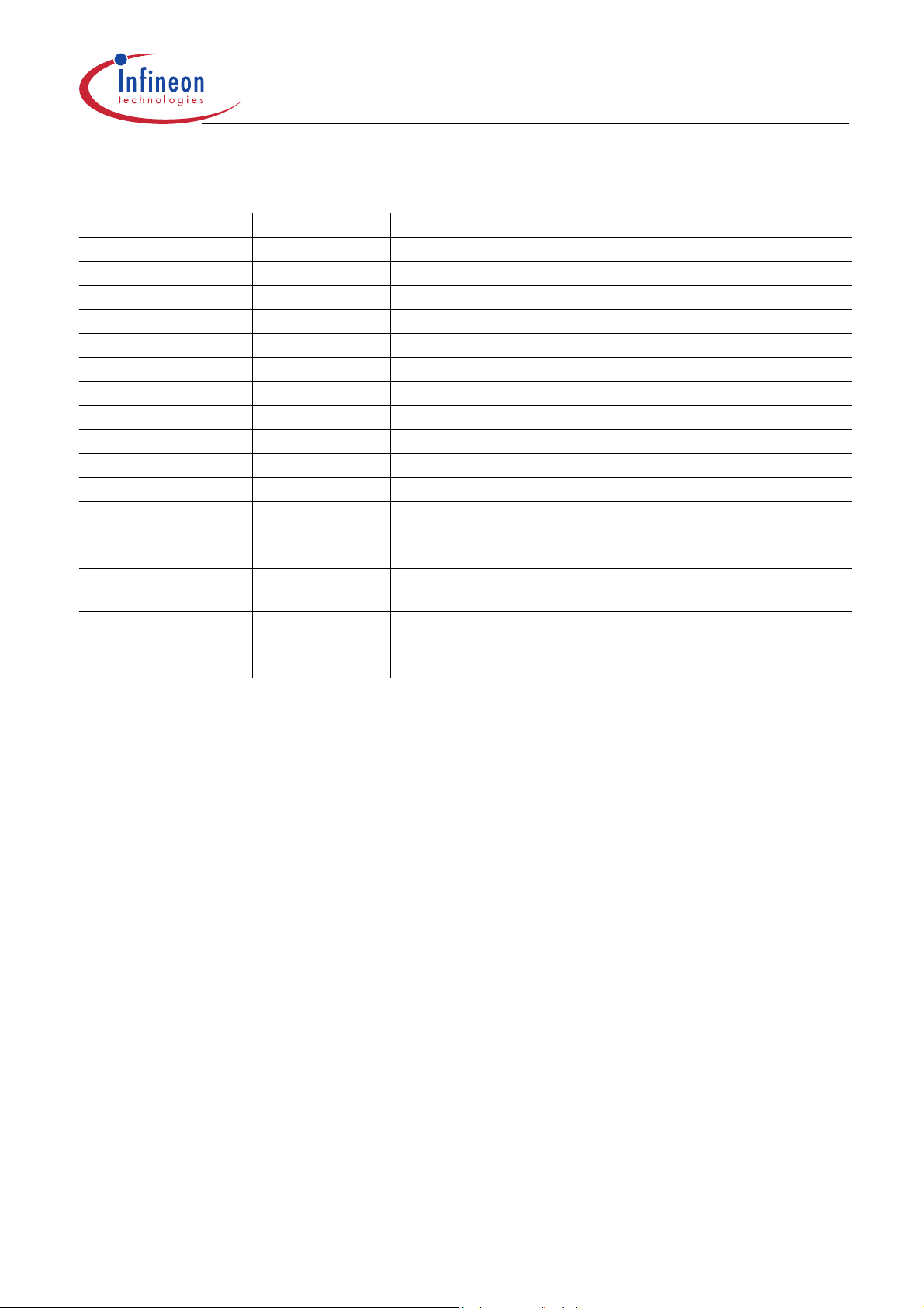
Table 2 Ordering Information
Type Speed Grade Package Description
HYB 39S256400DT-6 PC166-333-520 P-TSOP-54-2 (400mil) 166MHz 4B x 16M x 4 SDRAM
HYB 39S256400DT-7 PC133-222-520 P-TSOP-54-2 (400mil) 143MHz 4B x 16M x 4 SDRAM
HYB 39S256400DT-7.5 PC133-333-520 P-TSOP-54-2 (400mil) 133MHz 4B x 16M x 4 SDRAM
HYB 39S256400DT-8 PC100-222-620 P-TSOP-54-2 (400mil) 125MHz 4B x 16M x 4 SDRAM
HYB 39S256800DT-6 PC166-333-520 P-TSOP-54-2 (400mil) 166MHz 4B x 8M x 8 SDRAM
HYB 39S256800DT-7 PC133-222-520 P-TSOP-54-2 (400mil) 143MHz 4B x 8M x 8 SDRAM
HYB 39S256800DT-7.5 PC133-333-520 P-TSOP-54-2 (400mil) 133MHz 4B x 8M x 8 SDRAM
HYB 39S256800DT-8 PC100-222-620 P-TSOP-54-2 (400mil) 125MHz 4B x 8M x 8 SDRAM
HYB 39S256160DT-6 PC166-333-520 P-TSOP-54-2 (400mil) 166MHz 4B x 4M x 16 SDRAM
HYB 39S256160DT-7 PC133-222-520 P-TSOP-54-2 (400mil) 143MHz 4B x 4M x 16 SDRAM
HYB 39S256160DT-7.5 PC133-333-520 P-TSOP-54-2 (400mil) 133MHz 4B x 4M x 16 SDRAM
HYB 39S256160DT-8 PC100-222-620 P-TSOP-54-2 (400mil) 125MHz 4B x 4M x 16 SDRAM
HYB39S256400DTL-x – P-TSOP-54-2 (400mil) 4B x 16M x 4 SDRAM Low Power
Versions (on request)
HYB39S256800DTL-x – P-TSOP-54-2 (400mil) 4B x 8M x 8 SDRAM Low Power
Versions (on request)
HYB39S256160DTL-x – P-TSOP-54-2 (400mil) 4B x 4M x 16 SDRAM Low Power
Versions (on request)
HYB39S256xx0DC(L)-x – P-TFBGA-54 (on request)
Overview
Data Sheet 7 Rev. 1.02, 2004-02
10072003-13LE-FGQQ
HYB39S256[40/80/16]0D[C/T](L)
256-MBit Synchronous DRAM
2 Pin Configuration
2.1 Signal Pin Description
Table 3 Signal Pin Description
Pin Type Signal Polarity Function
CLK Input Pulse Positive
Edge
CKE Input Level Active
High
CS
RAS
CAS
WE
A0 - A12 Input Level – Address Inputs
BA0, BA1 Input Level – Bank Select
DQx Input
DQM
LDQM
UDQM
Input Pulse Active
Low
Input Pulse Active
Low
Level – Data Input/Output
Output
Input Pulse Active
High
Clock Input
The system clock input. All of the SDRAM inputs are sampled on the rising
edge of the clock.
Clock Enable
Activates the CLK signal when high and deactivates the CLK signal when
low, thereby initiating either the Powe r Down mode, Suspend mode, or the
Self Refresh mode.
Chip Select
CS
enables the command decoder when low and disables the command
decoder when high. When the command decoder is disabled, new
commands are ignored but previous operations continue.
Command Signals
When sampled at the positive rising edge of the clock, CAS
define the command to be executed by the SDRAM.
During a Bank Activate command cycle, A0-A12 define the row address
(RA0-RA12) when sampled at the rising clock edge.
During a Read or Write command cycle, A0-An define the column address
(CA0-CAn) when sampled at the rising clock edge. CAn depends upon the
SDRAM organization:
64M x4 SDRAM CAn = CA9, CA11 (Page Length = 2048 bits)
32M x8 SDRAM CAn = CA9 (Page Length = 1024 bits)
16M x16 SDRAM CAn = CA8 (Page Length = 512 bits)
In addition to the column address, A10 (= AP) is used to invoke the
autoprecharge operation at the end of the b urst read or write cycle . If A10
is high, autoprecharge is selected and BA0, BA1 defines the bank to be
precharged. If A10 is low, autoprecharge is disabled.
During a Precharge command cycle, A10 (= AP) is used in conjunction
with BA0 and BA1 to control which bank(s) to pr echarge. If A10 is h igh, all
four banks will be precharged regardless of the state of BA0 and BA1. If
A10 is low, then BA0 and BA1 are used to define which bank to precharge.
Bank Select Inputs. Bank address inputs selects which of the four banks a
command applies to.
Data Input/Output pins operate in the same manner as on EDO or FPM
DRAMs.
Data Mask
The Data Input/Output mask places the DQ buffers in a high impedance
state when sampled high. In Read mode, DQM has a latency of two clock
cycles and controls the output buffers like an output enable. In Write mo de,
DQM has a latency of zero and operates as a word mask by allowing input
data to be written if it is low but blocks the write operation if DQM is high.
One DQM input is present in x4 and x8 SDRAMs, LDQM and UDQM
controls the lower and upper bytes in x16 SDRAMs.
Pin Configuration
, RAS, and WE
Data Sheet 8 Rev. 1.02, 2004-02
10072003-13LE-FGQQ
HYB39S256[40/80/16]0D[C/T](L)
256-MBit Synchronous DRAM
Table 3 Signal Pin Description
Pin Type Signal Polarity Function
V
DD VSS
Supply – – Power and Ground
Power and ground for the input buffers and the core logic (3 .3 V)
V
DDQ VSSQ
Supply – – Power and Ground for DQs
Isolated power supply and ground for the output buffers to provide
improved noise immunity.
NC – – – Not Connected
No internal electrical connection is present.
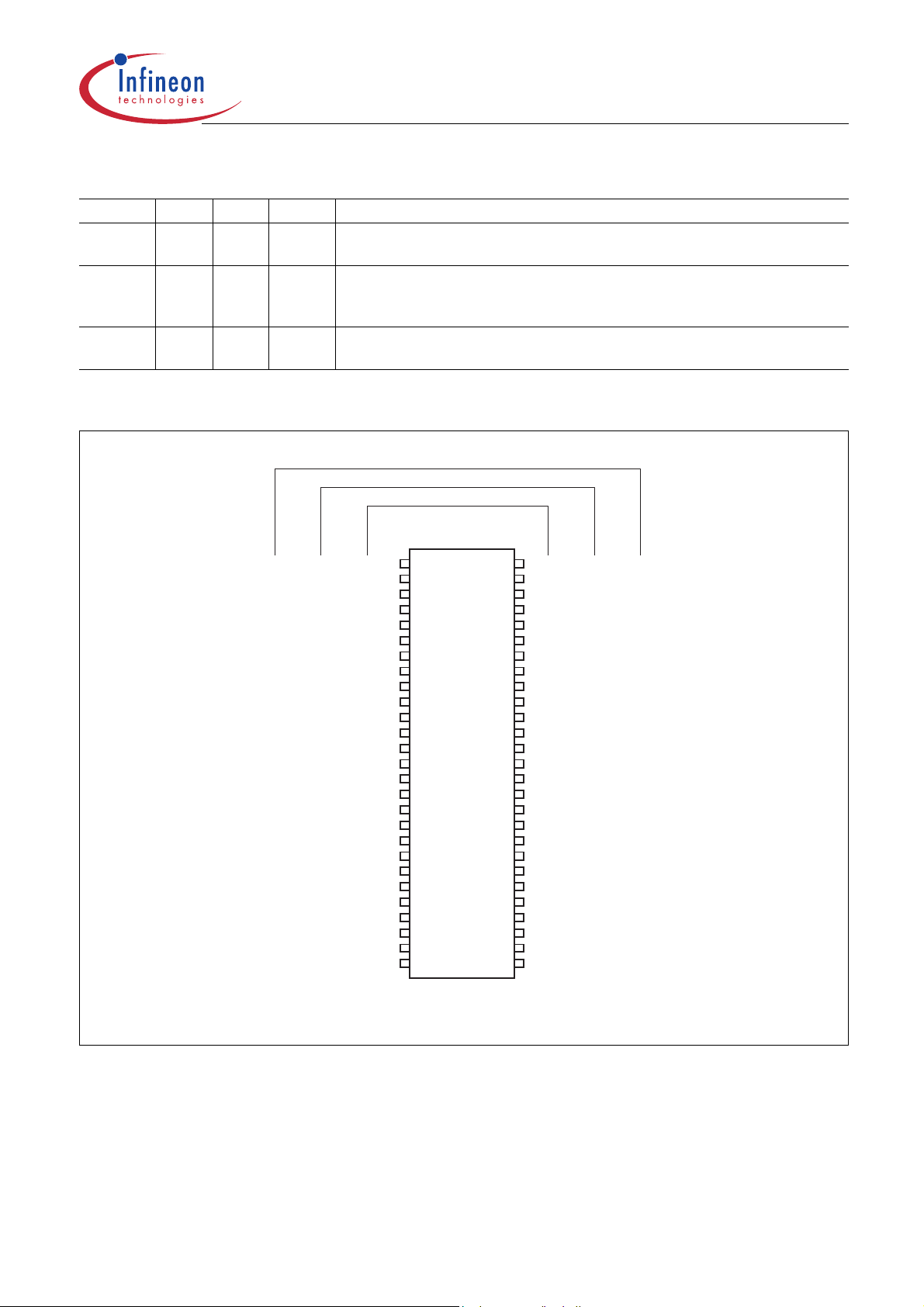
2.2 Package P–TSOPII–54
16 M x 16
32 M x 8
64 M x 4
V
V
DD
DD
DQ0
DQ0
V
V
DDQ
SSQ
DDQ
SSQ
DD
DD
DDQ
N.C.
DQ1
V
SSQ
N.C.
DQ2
V
DDQ
N.C.
DQ3
V
SSQ
N.C.
V
DD
N.C.
WE
CAS
RAS
CS
BA0
A10/AP
A0
A1
A2
A3
V
DD
DQ1
DQ2
V
DQ3
DQ4
V
DQ5
DQ6
V
DQ7
V
LDQM
WE
CAS
RAS
CS
BA0
BA1 BA1
A10/AP
A0
A1
A2
A3
V
V
DD
N.C.
V
DDQ
N.C.
DQ0
V
SSQ
N.C.
N.C.
V
DDQ
N.C.
DQ1
V
SSQ
N.C.
V
DD
N.C.
WE
CAS
RAS
CS
BA0
BA1
A10/AP
A0
A1
A2
A3
V
DD
1
2
3
4
5
6
7
8
9
10
11
12
13
14
15
16
17
18
19
20
21
22
23
24
25
26
27
54
53
52
51
50
49
48
47
46
45
44
43
42
41
40
39
38
37
36
35
34
33
32
31
30
29
28
V
N.C.
V
N.C.
DQ3
V
N.C.
N.C.
V
N.C.
DQ2
V
N.C.
V
N.C.
DQM
CLK
CKE
A12
A11
A9 A9
A8
A7
A6
A5
A4
V
SS
SSQ
DDQ
SSQ
DDQ
SS
SS
V
DQ7
V
N.C.
DQ6
V
N.C.
DQ5
V
N.C.
DQ4
V
N.C.
V
N.C.
DQM
CLK
CKE
A12
A11
A8
A7
A6
A5
A4
V
SS
SSQ
DDQ
SSQ
DDQ
SS
SS
V
SS
DQ15
V
SSQ
DQ14
DQ13
V
DDQ
DQ12
DQ11
V
SSQ
DQ10
DQ9
V
DDQ
DQ8
V
SS
N.C.
UDQM
CLK
CKE
A12
A11
A9
A8
A7
A6
A5
A4
V
SS
Pin Configuration
TSOPII-54 (400 mil x 875 mil, 0.8 mm pitch)
SPP04126
Figure 1 Pinouts P–TSOPII–54
Data Sheet 9 Rev. 1.02, 2004-02
10072003-13LE-FGQQ

HYB39S256[40/80/16]0D[C/T](L)
256-MBit Synchronous DRAM
Pin Configuration
2.3 Package P–TFBGA–54
Table 4 Pin Configuration for x16 devices
123 7 8 9
V
SS
DQ14 DQ13 V
DQ12 DQ11
DQ10 DQ9
DQ8 NC
V
REF
A12 A11 A9 G BA0 BA1 CS
A8 A7 A6 H A0 A1 A10
V
SS
Table 5 Pin Configuration for x8 devices
123 7 8 9
V
SS
NC DQ6 V
NC DQ5
NC DQ4
NC NC
DQM CLK CKE F CAS
A12 A11 A9 G BA0 BA1 CS
A8 A7 A6 H A0 A1 A10
V
SS
DQ15 V
V
V
V
SSQ
DDQ
SSQ
DDQ
SS
A V
B V
C V
D V
DDQ
SSQ
DDQ
SSQ
ENCV
DQ0 V
DQ2 DQ1
DQ4 DQ3
DQ6 DQ5
DDQ
NC
DM F CAS RAS WE
A5 A4 J A3 A2 V
DQ7 V
V
V
V
SSQ
DDQ
SSQ
DDQ
SS
A V
B V
C V
D V
E V
DDQ
SSQ
DDQ
SSQ
DD
DQ0 V
DQ2 NC
DQ3 NC
DQ6 NC
NC NC
RAS WE
A5 A4 J A3 A2 V
DD
DD
DD
DD
Table 6 Pin Configuration for x4 devices
123 7 8 9
V
SS
NC DQ3 V
NC NC
NC DQ2
NC NC
DQM CLK CKE F CAS
NC V
V
V
V
SSQ
DDQ
SSQ
DDQ
SS
A V
B V
C V
D V
E V
DDQ
SSQ
DDQ
SSQ
DD
NC V
DD
DQ0 NC
NC NC
DQ1 NC
NC NC
RAS WE
A12 A11 A9 G BA0 BA1 CS
A8 A7 A6 H A0 A1 A10
V
SS
A5 A4 J A3 A2 V
DD
Data Sheet 10 Rev. 1.02, 2004-02
10072003-13LE-FGQQ

HYB39S256[40/80/16]0D[C/T](L)
256-MBit Synchronous DRAM
2.4 Block Diagrams
Column Address
Counter
Row
Decoder
Memory
Arra y
&I(O)Bus
Bank 0
8196
Column Decoder
x2048
x4Bit
Sense amplifier
Colum n A ddresses Row A ddresses
A0 - A9, A11, AP,
BA0, BA1
Column A ddress
Buffer
Row
Decoder
Memory
Arra y
r
Bank 1
8192
Column Decode
se ampl ifier & I(O) Bus
x2048
x4Bit
Sen
A0 - A12,
BA0, BA1
Row Address
Buffer
Row
Decoder
Memory
Arra y
Bank 2
mn Decoder
8192
Colu
x 2048
x4Bit
Sense amplifier& I(O) Bus
Refresh C ounter
Row
Decoder
Memory
Array
Bank 3
8192
Column Decoder
x2048
x4Bit
Sense amplifier& I(O) Bus
Pin Configuration
In p ut B uf fe r O u tp u t B u ffe r
DQ0 - DQ3
Figure 2 Block Diagram for 64M x 4 SDRAM (13/11/2 addressing)
Control L ogic &
Tim ing G enerator
CLK
CKECSRAS
CAS
SPB 04127_2
WE
DQM
Data Sheet 11 Rev. 1.02, 2004-02
10072003-13LE-FGQQ

HYB39S256[40/80/16]0D[C/T](L)
256-MBit Synchronous DRAM
Column Addresses Row Addresses
A0 - A12,
BA0, BA1
Row Address
Buffer
Row
Decoder
Memory
Array
Bank 2
8192
Column Decoder
x 1024
x 8 Bit
Sense amplifier & I(O) Bus
Refresh Counter
Row
Decoder
Memory
Array
Bank 3
8192
Column Decoder
x 1024
x 8 Bit
Sense amplifier & I(O) Bus
Column Address
Counter
Row
Decoder
Memory
Array
Bank 0
Column Decoder
8192
x 1024
x 8 Bit
Sense amplifier & I(O) Bus
A0 - A9, AP,
BA0, BA1
Column Address
Buffer
Row
Decoder
Memory
Array
Bank 1
8192
Column Decoder
x 1024
x 8 Bit
Sense amplifier & I(O) Bus
Pin Configuration
Input Buffer Output Buffer
DQ0 - DQ7
Figure 3 Block Diagram for 32M x 8 SDRAM (13/10/2 addressing)
Control Logic &
Timing Generator
CS
CLK
RAS
CKE
CAS
SPB04128
WE
DQM
Data Sheet 12 Rev. 1.02, 2004-02
10072003-13LE-FGQQ

HYB39S256[40/80/16]0D[C/T](L)
256-MBit Synchronous DRAM
Column Addresses Row Addresses
A0 - A12,
BA0, BA1
Row Address
Buffer
Row
Decoder
Memory
Array
Bank 2
Column Decoder
8192 x 512
x 16 Bit
Sense amplifier & I(O) Bus
Refresh Counter
Row
Decoder
Memory
Array
Bank 3
Column Decoder
8192 x 512
x 16 Bit
Sense amplifier & I(O) Bus
Column Address
Counter
Row
Decoder
Memory
Array
Bank 0
Column Decoder
8192 x 512
x 16 Bit
Sense amplifier & I(O) Bus
A0 - A8, AP,
BA0, BA1
Column Address
Buffer
Row
Decoder
Memory
Array
Bank 1
Column Decoder
8192 x 512
x 16 Bit
Sense amplifier & I(O) Bus
Pin Configuration
Input Buffer Output Buffer
DQ0 - DQ15
Figure 4 Block Diagram for 16M x 16 SDRAM (13/9/2 addressing)
Control Logic &
Timing Generator
CS
CLK
RAS
CKE
CAS
WE
DQMU
SPB04129
DQML
Data Sheet 13 Rev. 1.02, 2004-02
10072003-13LE-FGQQ

HYB39S256[40/80/16]0D[C/T](L)
256-MBit Synchronous DRAM
Functional Description
3 Functional Description
3.1 Operation Definition
All of SDRAM operations are defined by states of control signals CS, RAS, CAS, WE, and DQM at the positive
edge of the clock. The following list shows the truth table for the operation commands.
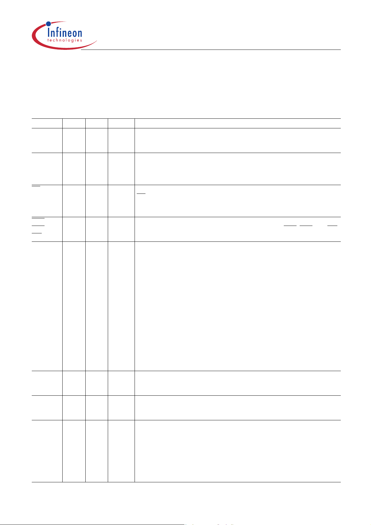
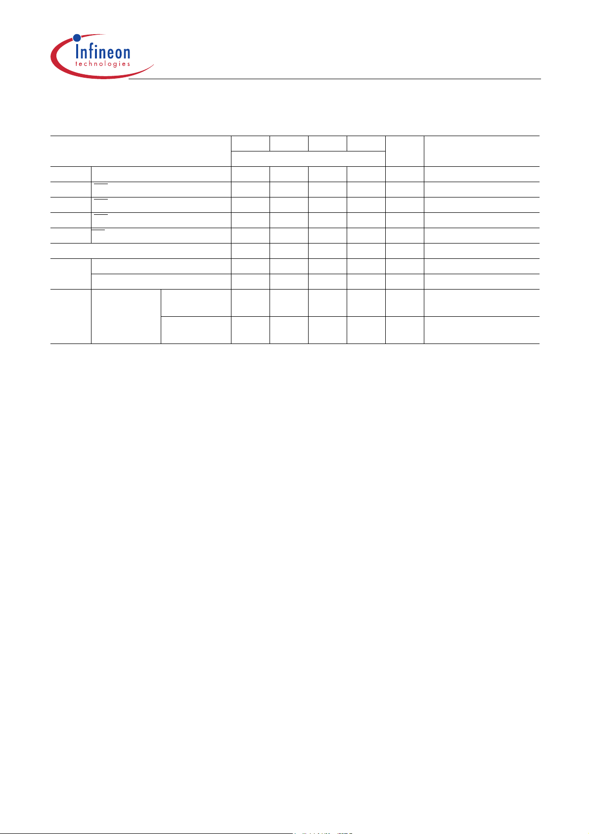
Table 7 Truth Table: Operation Command
Operation Device State CKE
n-1
Bank Active Idle
Bank Precharge Any H X X V L X L L H L
Precharge All Any H X X X H X L L H L
Write Active
Write with
Autoprecharge
Read Active
Read with
Autoprecharge
Mode Register Set Idle H X X V V V L L L L
No Operation Any H X X X X X L H H H
Burst Stop Active H X X X X X L H H L
Device Deselect Any H X X X X X H X X X
Auto Refresh Idle H H X X X X L L L H
Self Refresh Entry I dle H L X X X X L L L H
Self Refresh Exit Idle (Self Refr.) L H X X X X H X X X
Clock Suspend Entry Active H L X X X X X X X X
Power Down Entry
(Precharge or active
standby)
Clock Suspend Exit Active
Power Down Exit Any (Power
Data Write/Output
Enable
Data Write/Output
Disable
3)
3)
3)
Active
3)
3)
Active
Idle H L X X X X H X X X
Active L H H H
4)
Down)
Active H X L X X X X X X X
Active H X H X X X X X X X
HXXVVVLLHH
HXXVLVLHLL
HXXVHVLHLL
HXXVLVLHLH
HXXVHVLHLH
LHXXXXXXXX
LHXXXXHXXX
1)2)
CKE
1)2)
n
DQM
1)2)
BA0
BA1
1)2)
AP=
A10
1)2)
Addr.
1)2)
CS
RAS
1)2)
CAS
1)2)WE1)2)
1)2)
LH H X
LH H L
1) V = Valid, x = Don’t Care, L = Low Level, H = High Level
2) CKEn signal is input level when commands are provided, CKEn-1 signal is input level one clock before the commands are
provided.
3) This is the state of the banks designated by BA0, BA1 signals.
4) Power Down Mode can not be entered in a burst cycle. When this command asserted in the burst mode cycle device is in
clock suspend mode.
Data Sheet 14 Rev. 1.02, 2004-02
10072003-13LE-FGQQ

HYB39S256[40/80/16]0D[C/T](L)
256-MBit Synchronous DRAM
Functional Description
3.2 Initialization
The default power on state of the mode register is supplier specific and may be undefined. The following power
on and initialization sequence guarantees the device is preconditioned to each users specific needs. Like a
conventional DRAM, the Synchronous DRAM must be powered up and init ialized in a predef ined ma nner. Dur ing
power on, all
are held in the “NOP” state. The power on voltage must not exceed
supplies. The CLK signal must be started at the sa me t ime. After power on, an initial pause of 200 ms is required
followed by a precharge of all banks using the precharge command. To prevent data contention on the DQ bus
during power on, it is required that the DQM and CKE pins be held high during the initial pause period. Once all
banks have been precharged, the Mode Register Set Comm and must be issue d to initialize th e Mode Registe r. A
minimum of eight Auto Refresh cycles (CBR) are also required.These may be done before or after programming
the Mode Register. Failure to follow these steps may lead to unpredictable start-up modes.
V
and V
DD
pins must be built up simultaneously to the specified voltage when the input signals
DDQ
V
+0.3V on any of the input pins or V
DD
DD
3.3 Mode Register Definition
The Mode register designates the operation mode at the re ad or write cycle. This register is divided into f our fields.
First, a Burst Length Field which sets the length of the b urst, Second, an Addressing Select ion bit which programs
the column access sequence in a burst cycle (interleaved or sequential). Third, a CAS
access time at clock cycle. Fourth, an Operation mode f ield t o differ entiate betwee n normal op erat ion (Burst read
and burst Write) and a special Burst Read and Single Write mode. After the initial power up, the mode set
operation must be done before any activate command. Any content of the mode register can be altered by reexecuting the mode set command. All banks must be in precharged state and CKE must be high at least one clock
before the mode set operation. After the mode register is set, a Standby or NOP command is r equired. Low signals
of RAS
timing defines parameters to be set as shown in the previous table.
, CAS, and WE at the positive edge of the clock activate the mode set operation. Address input data at t his
Latency Field to set the
Data Sheet 15 Rev. 1.02, 2004-02
10072003-13LE-FGQQ

HYB39S256[40/80/16]0D[C/T](L)
256-MBit Synchronous DRAM
MR
Mode Register Definition (BA[1:0] = 00
BA1BA0A12A11A10A9A8A7A6A5A4A3A2A1A0
0 0 MODE CL BT BL
reg. addr w w w w
Field Bits Type Description
BL [2:0] w Burst Length
Number of sequential bits per DQ related to one read/write command, see
Chapter 3.3.1
Note:All other bit combinations are RESERVED
000 1
001 2
010 4
011 8
111 Full Page (Sequential burst type only)
BT 3wBurst Type
See Table 8 for internal address sequence of low order address bits.
0 Sequential
1 Interleaved
CL [6:4] w CAS Latency
Number of full clocks from read command to first data valid window.
Note:All other bit combinations are RESERVED.
)
B
Functional Description
Operating
Mode
010 2
011 3
[13:7] w Operating Mode
Note:All other bit combinations are RESERVED.
0 burst read/burst write
1 burst read/single write
Data Sheet 16 Rev. 1.02, 2004-02
10072003-13LE-FGQQ

HYB39S256[40/80/16]0D[C/T](L)
256-MBit Synchronous DRAM
Functional Description
3.3.1 Burst Length
Table 8 Burst Length and Sequence
Burst Length Starting Column Address Order of Accesses within a Burst
A2 A1 A0 Type=Sequential Type=Interleaved
2 0 0–1 0–1
1 1–0 1–0
4 0 0 0–1–2–3 0–1–2–3
0 1 1–2–3–0 1–0–3–2
1 0 2–3–0–1 2–3–0–1
1 1 3–0–1–2 3–2–1–0
8 0 0 0 0–1–2–3–4–5–6–7 0–1–2–3–4–5–6–7
0 0 1 1–2–3–4–5–6–7–0 1–0–3–2–5–4–7–6
0 1 0 2–3–4–5–6–7–0–1 2–3–0–1–6–7–4–5
0 1 1 3–4–5–6–7–0–1–2 3–2–1–0–7–6–5–4
1 0 0 4–5–6–7–0–1–2–3 4–5–6–7–0–1–2–3
1 0 1 5–6–7–0–1–2–3–4 5–4–7–6–1–0–3–2
1 1 0 6–7–0–1–2–3–4–5 6–7–4–5–2–3–0–1
1 1 1 7–0–1–2–3–4–5–6 7–6–5–4–3–2–1–0
FullPage n Cn, Cn+1, Cn+2 .... not supported
Note:
1. For a burst length of two, A1-Ai selects the two-data-element block; A0 select s the first access within the block.
2. For a burst length of four, A2-Ai selects the four-data-element block; A0-A1 selects the first access within the
block.
3. For a burst length of eight, A3-Ai selects the eight-data- element block; A0-A2 selects the first access withinthe
block.
4. Whenever a boundary of the block is reached within a given seque nce above, the following access wrapswithin
the block.
3.4 Commands
Refresh Mode
SDRAM has two refresh modes, Auto Refresh and Self Refresh. Auto Refresh is similar to the CAS
refresh of conventional DRAMs. All banks must be precharged before applying any refresh mode. An on-chip
address counter increments the wor d and the bank addre sses and no bank inform ation is required for both refresh
modes.
The chip enters the Auto Refresh mode, when RAS
timing. The mode restores word line after the refresh and no external precharge command is necessary.
Aminimum tRC time is required between two automatic refreshes in a burst ref resh mod e. The same rule applies
toany access command after the automatic refresh operation.
The chip has an on-chip timer and the Self Refr esh mode is available. The mode restores the word lines af ter RAS
CAS
, and CKE are low and WE is high at a clock timing. All of external control signals including the clock
aredisabled. Returning CKE to high enables the clock and initiates the refresh exit operation. After the exit
command,at least one
t
delay is required prior to any access command.
RC
and CAS are held low and CKE and WE are held high at aclock
-before-RAS
,
Data Sheet 17 Rev. 1.02, 2004-02
10072003-13LE-FGQQ

HYB39S256[40/80/16]0D[C/T](L)
256-MBit Synchronous DRAM
Auto Precharge
Two methods are available to precharge SDRAMs. I n an auto matic precharge m ode, the CAS
extra address, CA10, to determine whether the chip restores or not after the operation. If CA10 is high when a
Read Command is issued, the Read with Auto-Precharge function is initiated. If CA10 is high when a Write
Command is issued, the Write with Auto-Precharge function is initiated. The SDRAM automatic ally enters the
precharge operation a time delay equal to
Auto-Precharge may only be interrupted by a burst start t o another bank. It must n ot be interrupted by a pr echarge
or a burst stop command.
Precharge Command
There is also a separate precharge command available. When RAS
timing, it triggers the precharge operation. Three address bits, BA0, BA1 and A10 are used to define banks as
shown in the following list. The precharge command can be imposed one clock before the last data out for CAS
latency = 2 and two clocks before the last data out for CAS latency = 3. Writes require a time delay twr (“write
recovery time”) of 2 clocks minimum from the last data out to apply the precharge command.
Table 9 Bank Selection by Addr e ss Bits
A10 BA0 BA1
0 00Bank 0
0 01Bank 1
0 10Bank 2
0 11Bank 3
1 1 X all Banks
t
(“write recovery time”) after the last data in. A burst operation with
WR
and WE are low and CAS is high at a clock
Functional Description
timing accepts one
Burst Termination
Once a burst read or write operation has bee n initi ated, t here ar e several met hods in which to te rminate the bu rst
operation prematurely. These methods include using another Read or Write Command to interrupt an existing
burst operation, use a Precharge Command to in terrupt a burst cycle and close the active bank, or u sing the Burst
Stop Command to terminate the existing burst operation but leave the bank open for future Read or Write
Commands to the same page of the active bank. When inter rupting a bur st with another Re ad or Write Command
care must be taken to avoid DQ contention. The Burst Stop Command, however, has the fewest restrictions
making it the easiest method to use when terminating a burst operation before it has been completed. If a Burst
Stop command is issued during a burst write operation, then any residual data from the burst write cycle will be
ignored. Data that is presented on the DQ pins before the Burst Stop Command is registered will be written to the
memory.
3.5 Operations
3.5.1 Read and Write
When RAS is low and both CAS and WE are high at the positive edge of the clock, a RAS cycle starts. According
to address data, a word line of the selected bank is activat ed and all of sense amplifiers associated to the wordline
are set. A CAS
from the RAS timing. WE is used to define either a read (WE = H) or a write (WE = L) at this stage.
SDRAM provides a wide variety of fast access modes. In a single CAS
are allowed at up to a 166 MHz data rate. T he number s of ser ial data b its are the burst leng th pr ogra mmed at t he
mode set operation, i.e., o ne of 1 , 2, 4 and 8 and full p age. Column addresses a re segm ented by th e bur st leng th
and serial data accesses are done within this boundary. The first column address to be accessed is supplied at
the CAS
its sequence. For example, in a burst length of 8 with interleave sequence, if the first address is ‘2’, then the rest
of the burst sequence is 3, 0, 1, 6, 7, 4, and 5.
Data Sheet 18 Rev. 1.02, 2004-02
10072003-13LE-FGQQ
cycle is triggered by setting RAS high and CAS low at a clock timing after a necessary delay, t
cycle, serial data read or write operations
timing and the subsequent addresses are generated automatically by the programmed burst length and
RCD

HYB39S256[40/80/16]0D[C/T](L)
256-MBit Synchronous DRAM
Full page burst operation is only possible using the sequential burst type and page length is a function of the I/O
organization and column addressing. Full page burst operation does not self terminate once the burst length has
been reached. In other words, unlike burst lengths of 2, 4 and 8, fulll page burst continues until it is terminated
using another command.
Similar to the page mode of conventional DRAMs, burst read or write accesses on any column address are
possible once the RAS
number of random column accesses. A new burst access can be done even before the previous burst ends. The
interrupt operation at every clock cycle is supported. When the previous burst is interrupted, the remaining
addresses are overridden by the new address with the full burst length. An interrupt which accompanies an
operation change from a read to a write is possible by exploiting DQM t o avoid bus contention.
When two or more banks are activated sequentially, interleaved bank read or write operations are possible. With
the programmed burst length, alternate access and precharge operations on two or more banks can realize fast
serial data access modes among many different p ages. Once two or more banks are act ivated, column to column
interleave operation can be performed between different pages.
cycle latches the sense amplifiers. The maximum t
or the refresh interval time limits the
RAS
Functional Description
3.5.2 DQM Function
DQM has two functions for data I/O read and write operations. During reads, when it turns to “high“ at a clock
timing, data outputs are disabled and become high impedance after two clock delay (DQM Data Disable Latency
t
). It also provides a data mask function for writes. When DQM is activated, the write operation at the next clock
DQZ
is prohibited (DQM Write Mask Latency
t
= zero clocks).
DQW
3.5.3 Suspend Mode
During normal access mode, CKE is held high enabling the clock. When CKE is low, it freezes the internal clock
and extends data read and write operations. One clock delay is required for mode entry and exit (Clock Suspend
Latency
t
).
CSL
3.5.4 Power Down
In order to reduce standby power consumption, a power down mode is available. All banks must be precharged
and the necessary Precharge delay (
the Power Down mode is initiated by holding CKE low, all of the receiver circuits except CLK and CKE are gated
off. The Power Down mode does not perform any refresh operations, therefore the device can’t remain in Power
Down mode longer than the Refresh period
“high“. One clock delay is required for Power Down mode ent ry an d ex it.
t
) must occur before the SDRAM can enter the Power Down mode. Once
RP
(t
) of the device. Exit from this mode is performed by taking CKE
REF
Data Sheet 19 Rev. 1.02, 2004-02
10072003-13LE-FGQQ

HYB39S256[40/80/16]0D[C/T](L)
256-MBit Synchronous DRAM
Electrical Characteristics
4 Electrical Characteristics
4.1 Operating Conditions
Table 10 Absolute Maximum Ratings
Parameter Symbol Limit Values Unit Note/
min. max.
Input / Output voltage relative to
Voltage on
Voltage on
V
supply relative to V
DD
V
supply relative to V
DDQ
Operating Temperature
Storage temperature range
Power dissipation per SDRAM component
Data out current (short circuit)
V
SS
SS
SS
V
IN, VOUT
V
DD
V
DDQ
T
A
T
STG
P
D
I
OUT
– 1.0 +4. 6 V –
–1.0 +4.6 V –
–1.0 +4.6 V –
0+70οC–
-55 +150
o
C–
–1 W–
–50mA–
Attention: Permanent device damage may occur if “Absolute Maximum Ratings” are exceeded.Functional
operation should be restricted to recommended operation conditions. Expo sure to higher tha n
recommended voltage for extended periods of time affect device reliabilit y
Test Condition
Table 11 DC Characteristics
1)
Parameter Symbol Values Unit Note/
min. max.
Supply Voltage
I/O Supply Voltage V
Input high voltage V
Input low voltage V
Output high voltage (I
Output low voltage (I
= – 4.0 mA) V
OUT
= 4.0 mA) V
OUT
Input leakage current, any input
(0 V <
V
< VDD, all other inputs = 0 V)
IN
Output leakage current
V
(DQs are disabled, 0 V <
1) T
= 0 to 70 οC
A
2) All voltages are referenced to V
3) VIH may overshoot to V
with 3.3V. Pulse width measured at 50% points with amplitude measured peak to DC reference
< V
OUT
+ 2.0 V for pulse width of < 4ns with 3.3V. VIL may undershoot to -2.0 V for pulse width < 4.0 ns
DDQ
SS
DDQ
)
V
I
I
IL
OL
DD
DDQ
IH
IL
OH
OL
3.0 3.6 V
3.0 3.6 V
2.0 V
DDQ
+0.3 V
– 0.3 +0. 8 V
2.4 – V
–0.4V
– 5 +5 mA –
– 5 +5 mA –
Test Condition
2)
2)
2)3)
2)3)
2)
2)
.
Data Sheet 20 Rev. 1.02, 2004-02
10072003-13LE-FGQQ
HYB39S256[40/80/16]0D[C/T](L)
256-MBit Synchronous DRAM
Table 12 Input and Output Capacitances
Parameter Symbol Values
Input Capacitances: CK, CK
Input Capacitance
(A0-A12, BA0, BA1, RAS
Input/Output Capacitance (DQ) C
1) TA = 0 to 70 °C; VDD,VDDQ = 3.3 V ± 0.3 V, f = 1 MHz
2) Capacitance values are shown for TSOP-54 packages. Capacitance values for TFBGA packages are lower by 0.5 pF
Table 13
Parameter Symbol
Operating Current
One bank active, Burst length = 1
Precharge Standby Current in Power Down Mode I
Precharge Standby Current in Non-Power Down Mode I
No Operating Current
active state ( max. 4 banks)
Burst Operating Current
Read command cycling
Auto Refresh Current
Auto Refresh command cycling
Self Refresh Current (standard components)
Self Refresh Mode, CKE=0.2V,
Self Refresh Current (low power components)
Self Refresh Mode, CKE=0.2V,
I
Conditions
DD
, CAS, WE, CS, CKE, DQM)
t
=infinity
CK
t
=infinity
CK
1)
C
I1
C
I2
I0
Electrical Characteristics
2)
min. max.
2.5 3.5 pF
2.5 3.8 pF
4.0 6.0 pF
Unit
I
DD1
DD2P
DD2N
I
DD3N
I
DD3P
I
DD4
I
DD5
I
DD6
Data Sheet 21 Rev. 1.02, 2004-02
10072003-13LE-FGQQ
HYB39S256[40/80/16]0D[C/T](L)
256-MBit Synchronous DRAM
Table 14
I
Specifications and Conditions
DD
1)
Electrical Characteristics
Symbol -6 -7 -7.5 -8 Unit Note/ Test Condition
max.
I
DD1
I
DD2P
I
DD2N
I
DD3N
I
DD3P
I
DD4
I
DD5
I
DD6
t
= t
RC
CS =V
CS =V
CS = V
CS = V
, IO = 0 mA 100808080mA
RC(min)
IH (min.)
IH (min.)
IH(min)
IH(min)
, CKE ≤V
, CKE≥ V
, CKE ≥V
, CKE ≤ V
IL(max)
IH(min)
IH(min.)
IL(max.)
2222mA
35 30 30 25 mA
40 35 35 30 mA
5555mA
110909070mA
t
= t
RFC
RFC(min)
t
= 7.8 µs 3 3 3 3 mA
RFC
x4, x8, x16 standard
components31.5
low power
220 190 190 160 mA
3
1.5
3
1.5
3
1.5
0.85 0.85 0.85 0.85 mA
mA
mA
2)3)
2)
2)
2)
2)
2)3)
4)
components
1) TA = 0 to 70 °C; VSS = 0 V; VDD, V
2) These parameters depend on the cycle rate. All values are measured at 16 6 MHz for -6, at 133 MHz for
-7 and -7.5 and at 100 MHz for -8 components with the outputs open. Input signals are changed once during
3) These parameters are measured with continuous data stream during read access and all DQ toggling. CL=3 and BL=4 is
V
assumed and the
4) t
RFC
= t
RFC(min)
“burst refresh”, t
current is excluded.
DDQ
= 3.3 V ± 0.3 V
DDQ
= 7.8 µs “distributed refresh”.
RFC
t
.
CK
Data Sheet 22 Rev. 1.02, 2004-02
10072003-13LE-FGQQ

HYB39S256[40/80/16]0D[C/T](L)
256-MBit Synchronous DRAM
Electrical Characteristics
4.2 AC Characteristics
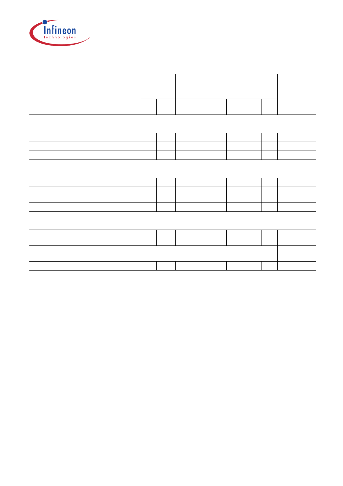
Table 15 AC Timing - Absolute Specifications –8/-7.5/–7/-6
Parameter Symbol –8 –7.5 –7 –6 Unit Notes
PC100 -
222
min. max. min. max. min. max. min. max
Clock and Clock Enable
Clock Cycle Time
CAS
Latency = 3
CAS
Latency = 2
Clock Frequency
CAS
Latency = 3
CAS
Latency = 2
Access Time from Clock
CAS
Latency = 3
CAS
Latency = 2
Clock High Pulse Width t
Clock Low Pulse Width
Transition time
t
CK
8
7.510—
10——
t
CK
——125
100——
t
AC
——6
——5.46——5.4
6
CH
t
CL
t
T
3 — 2.5 — 2.5 — 2 — ns
3 — 2.5 — 2.5 — 2 — ns
0.5 10 0.3 1.2 0.3 1.2 0.3 1.2 ns
1)2)3)
PC166 -
333
—
133
100——
PC166 -
222
7
7.5——
6
7.5——nsns
143
100——
5.4——55.4nsns
PC166 -
333
.
166
133
MHz
MHz
3)4)5)
Setup and Hold Times
Input Setup Time
Input Hold Time t
CKE Setup Time t
CKE Hold Time t
Mode Register Set-up to Active
delay
Power Down Mode Entry Time
Common Parameters
Row to Column Delay Time
Row Precharge Time t
Row Active Time t
Row Cycle Time t
Row Cycle Time during Auto
Refresh
Activate(a) to Activate(b)
Command period
CAS(a) to CAS(b) Command
period
t
IS
IH
CK
CKH
t
RSC
t
SB
t
RCD
RP
RAS
RC
t
RFC
t
RRD
t
CCD
2 — 1.5 — 1.5 — 1.5 — ns
1 — 0.8 — 0.8 — 0.8 — ns
2 — 1.5 — 1.5 — 1.5 — ns
1 — 0.8 — 0.8 — 0.8 — ns
6)
6)
6)
6)
2—2—2—2—CLK
08 07.507 06ns
20 — 20 — 15 — 15 — ns
20 — 20 — 15 — 15 — ns
48 100k 45 100k 37 100k 36 100k ns
70 — 67 — 60 — 60 — ns
7)
7)
7)
7)
70 — 67 — 63 — 60 — ns
16 — 15 — 14 — 12 — ns
7)
1—1—1—1—CLK
Refresh Cycle
Data Sheet 23 Rev. 1.02, 2004-02
10072003-13LE-FGQQ
HYB39S256[40/80/16]0D[C/T](L)
256-MBit Synchronous DRAM
Table 15 AC Timing - Absolute Specifications –8/-7.5/–7/-6 (cont’d)
1)2)3)
Electrical Characteristics
Parameter Symbol –8 –7.5 –7 –6 Unit Notes
PC100 -
222
PC166 -
333
PC166 -
222
PC166 -
333
min. max. min. max. min. max. min. max
.
Refresh Cycle
Refresh Period (8192 cycles)
Self Refresh Exit Time
Data Out Hold Time
t
REF
t
SREX
t
OH
– 64 – 64 – 64 – 64 ms
1—1—1—1—CLK
3—3—3—2.5—ns
3)5)
Read Cycle
Data Out to Low Impedance Time
Data Out to High Impedance
t
LZ
t
HZ
0—0—0—0—ns
38 37 37 36ns
Time
DQM Data Out Disable Latency
t
DQZ
—2 —2 —2 —2 CLK
Write Cycle
Last Data Input to Precharge
(Write without AutoPrecharge)
Last Data Input to Activate
t
WR
t
DAL(min.)(tWR/tCK
15 — 15 — 14 — 12 — ns
) + (tRP/tCK)CLK
8)
9)
(Write with AutoPrecharge)
DQM Write Mask Latency t
1) TA = 0 to 70 °C; VSS = 0 V; VDD, V
2) For proper power-up see the operation section of this data sheet.
3) AC timing tests for LV-TTL versions have
The transition time is measured between
shown in figure below. Specifie d
and with an input signal of 1V / ns edge rate between 0.8 V and 2.0 V.
4) If clock rising time is longer than 1 ns, a time (
Access time from clock tAC is 4.6 ns for PC133 components with no termination and 0 pF load,
5)
Data out hold time
6) If tT is longer than 1 ns, a time (tT- 1) ns has to be added to this parameter.
7) These parameter account for the number of clock cycles and depend on the operating frequency of the clock, as follows:
the number of clock cycles = specified value of timing period (counted in fractions as a whole number)
8) It is recommended to use two clock cycles between the last data-in and the precharge command in case of a write command
without Auto-Precharge. One clock cycle between the last data-in and the precharge command is also supported, but
restricted to cycle times tck greater or equal the specified twr value, where tck is equal to the actual system clock time.
9) Wh en a Write command with AutoPrecharge ha s been issued, a time of
Command can be applied. For each of the terms, if not al ready an integer, round up to the next highest integer.
to the actual system clock time.
t
is 1.8 ns for PC133 components with no termination and 0 pF load.
OH
DQW
= 3.3 V ± 0.3 V, tT = 1 ns
DDQ
t
and tOH parameters are measured with a 50 pF only, without any resistive termination
AC
0—0—0—0—CLK
V
= 0.4 V and VIH= 2.4 V with the timing referenced to the 1.4 V crossover point.
IL
V
and VIL. All AC measurements assume tT= 1 ns with the AC output load circuit
IH
t
/2 - 0.5) ns has to be added to this parameter.
T
t
has be fullfilled before the next Activate
DAL(min)
t
CK
is equal
Data Sheet 24 Rev. 1.02, 2004-02
10072003-13LE-FGQQ

HYB39S256[40/80/16]0D[C/T](L)
256-MBit Synchronous DRAM
t
CH
CLOCK
IN PUT
OUTPUT 1.4 V
Figure 5 Measurement conditions for
1.4 V
t
t
CL
t
t
IS
IH
1.4 V
t t
AC
t
LZ
T
AC
t
OH
t
HZ
2.4 V
0.4 V
t
IO.vsd
AC
and t
OH
I/O
Measurement conditions for
50 pF
t
and t
AC
OH
Electrical Characteristics
Data Sheet 25 Rev. 1.02, 2004-02
10072003-13LE-FGQQ

HYB39S256[40/80/16]0D[C/T](L)
256-MBit Synchronous DRAM
5 Package Outlines
Plastic Package P-TSOPII-54
(400 mil, 0.8 mm lead pitch)
Thin Small Outline Package, SMD
0.8
26x 0.8 =
3)
+0.1
0.35
-0.05
54 28
6 max
127
2.5 max
Index Marking
1)
Does not include plastic or metal protrusion of 0.15 max per side
2)
Does not include plastic protrusion of 0.25 max per side
3)
Does not include dambar protrusion of 0.13 max per side
22.22
±0.13
20.8
1)
15˚
15˚
Package Outlines
±5˚
±0.05
±0.05
0.1
1
±5˚
0.1
54x
0.2M54x
-0.03
+0.06
0.15
10.16
11.76
2)
±0.13
±0.1
0.5
±0.2
GPX09039
Figure 6 Package Outline P–TSOPII–54
Data Sheet 26 Rev. 1.02, 2004-02
10072003-13LE-FGQQ

HYB39S256[40/80/16]0D[C/T](L)
256-MBit Synchronous DRAM
TFBGA-54 package
(12 mm x 8 mm, 54 balls)
Package Outlines
Figure 7 Package Outline TFBGA-54
Data Sheet 27 Rev. 1.02, 2004-02
10072003-13LE-FGQQ

http://www.infineon.com
Published by Infineon Technologies AG
 Loading...