

Page 1

AN2019_09 EVAL
-C101T-IM231 User manual
EVAL-C101T-IM231 User manual
Motor Drive Evaluation Board Based On IMC101T-T038 and IM231-L6S1B
About this document
Scope and purpose
This user manual provides an overview of the evaluation board EVAL-C101T-IM231 including its main features,
key data, pin assignments and mechanical dimensions.
EVAL-C101T-IM231 is an evaluation-board as part of the evaluation design platform for motor drive based on
iMOTION™2.0 IMC100 Series. This board features and demonstrates Infineon’s advanced Motion Control Engine
(MCE) technology for permanent magnet motors drive over the full speed range. In the same time it features
and demonstrates Infineon’s CIPOSTM Micro IPM technology for motor drive.
The evaluation board EVAL-C101T-IM231 was developed to support customers during their first steps designing
applications with running any permanent magnet motor via sensor-less sinusoidal control.
Intended audience
This user manual is intended for all technical specialists working with the EVAL-C101T-IM231 board under
laboratory conditions.
Table of Contents
About this document ....................................................................................................................... 1
Table of Contents ........................................................................................................................... 1
1 Safety precautions ......................................................................................................... 2
2 Introduction .................................................................................................................. 3
3 Main features ................................................................................................................ 4
3.1 Key data ................................................................................................................................................... 5
3.2 The relationship between IO and F
3.3 Setting up the system.............................................................................................................................. 8
3.4 System debug process ............................................................................................................................ 9
3.5 MCEWizard setup overview ................................................................................................................... 10
3.6 MCEDesigner setup overview ................................................................................................................ 13
4 Pin assignments ........................................................................................................... 15
5 Schematics and Layout .................................................................................................. 16
5.1 EMI filter circuit ...................................................................................................................................... 16
5.2 Inverter section using CIPOSTM Micro IPM............................................................................................. 17
5.3 IMC101T-T038 Schematic Overview ..................................................................................................... 18
5.4 Auxiliary power supply .......................................................................................................................... 19
5.5 Inverter over current protection circuit................................................................................................ 19
5.6 PCB Layout ............................................................................................................................................ 20
6 Bill of Materials of EVAL-C101T-IM231 ............................................................................. 22
7 Reference .................................................................................................................... 25
Revision History ............................................................................................................................ 26
for EVAL-C101T-IM231................................................................ 8
PWM
User manual Please read the Important Notice and Warnings at the end of this document <Revision 1.0>
www.infineon.com <2019-07-30>
Page 2

Motor Drive Evaluation Board Based On IMC101T
-T038 and IM231
-
L6S1B
EVAL-C101T-IM231 User manual
Safety precautions
1
In addition to the precautions listed throughout this manual, please read and understand the following
statements regarding hazards associated with development systems.
Table 1
Safety precautions
Precautions
Caution: The ground potential of the EVAL-C101T-IM231 system is biased to a negative DC
bus voltage potential. When measuring voltage waveform by oscilloscope, the scope’s
ground needs to be isolated. Failure to do so may result in personal injury or death, and
equipment damage. Darkened display LEDs are not an indication that capacitors have
discharged to safe voltage levels.
Caution: EVAL-C101T-IM231 system contains DC bus capacitors which take time to
discharge after removal of the main supply. Before working on the drive system, wait
three minutes for capacitors to discharge to safe voltage levels. Failure to do so may
result in personal injury or death. Darkened display LEDs are not an indication that
capacitors have discharged to safe voltage levels.
Caution: Only personnel familiar with the drive and associated machinery should plan or
implement the installation, start-up and subsequent maintenance of the system. Failure
to comply may result in personal injury and/or equipment damage.
Caution: The surfaces of the drive may become hot, which may cause injury.
Caution: The EVAL-C101T-IM231 board contains parts and assemblies sensitive to
electrostatic discharge (ESD). Electrostatic control precautions are required when
installing, testing, servicing or repairing this assembly. Component damage may result if
ESD control procedures are not followed. If you are not familiar with electrostatic control
procedures, refer to applicable ESD protection handbooks and guidelines.
Caution: An incorrectly applied or installed drive can result in component damage or
reduction in product lifetime. Wiring or application errors such as undersized motor,
incorrect or inadequate DC supply, or excessive ambient temperatures may result in
system malfunction.
Caution: Remove AC input cable or turn off AC power supply. Wait three minutes after
removing power from the power drive to discharge the bus capacitors. Do not attempt to
service the drive until the bus capacitors have discharged to zero. Failure to do so may
result in personal injury or death.
Caution: The EVAL-C101T-IM231 board is shipped with packing materials that need to be
removed prior to installation. Failure to remove all packing materials which are
unnecessary for system installation may result in overheating or abnormal operating
condition.
User manual 2 <Revision 1.0>
<2019-07-30>
Page 3
Motor Drive Evaluation Board Based On IMC101T
-T038 and IM231
-
L6S1B
EVAL-C101T-IM231 User manual
Introduction
2
The EVAL-C101T-IM231 evaluation board is an evaluation design platform for complete inverter-controlled
motor drive applications based on iMOTIONTM2.0 chipset. As a form factor board for motor drive it contains
Controller (IMC101T-T038) and inverter (with CIPOSTM Micro IPM). The evaluation platform can easily be
debugged through the MCEDesigner and MCEWizard during customer first designing applications with
IMC101T-T038.
This evaluation board is designed to give comprehensible solutions of sensor-less control of permanent
magnet motors over the full speed range. It provides a single-phase AC-connector, rectifier, DC-link, controller
(with sensor less field oriented control), 3-phase output to motor. It is single shunt for current sensing and a
voltage divider for DC-link voltage measurement.
The EVAL-C101T-IM231 evaluation board is available from Infineon. The features of this board are described in
the design feature chapter of this document, whereas the remaining paragraphs provide information to enable
the customers to copy, modify and qualify the design for production according to their own specific
requirements.
Environmental conditions were considered in the design of the EVAL-C101T-IM231. The design was tested as
described in this document but not qualified regarding safety requirements or manufacturing and operation
over the whole operating temperature range or lifetime. The boards provided by Infineon are subject to
functional testing only.
Evaluation boards are not subject to the same procedures as regular products regarding Returned Material
Analysis (RMA), Process Change Notification (PCN) and Product Discontinuation (PD). Evaluation boards are
intended to be used under laboratory conditions by specialists only.
Introduction
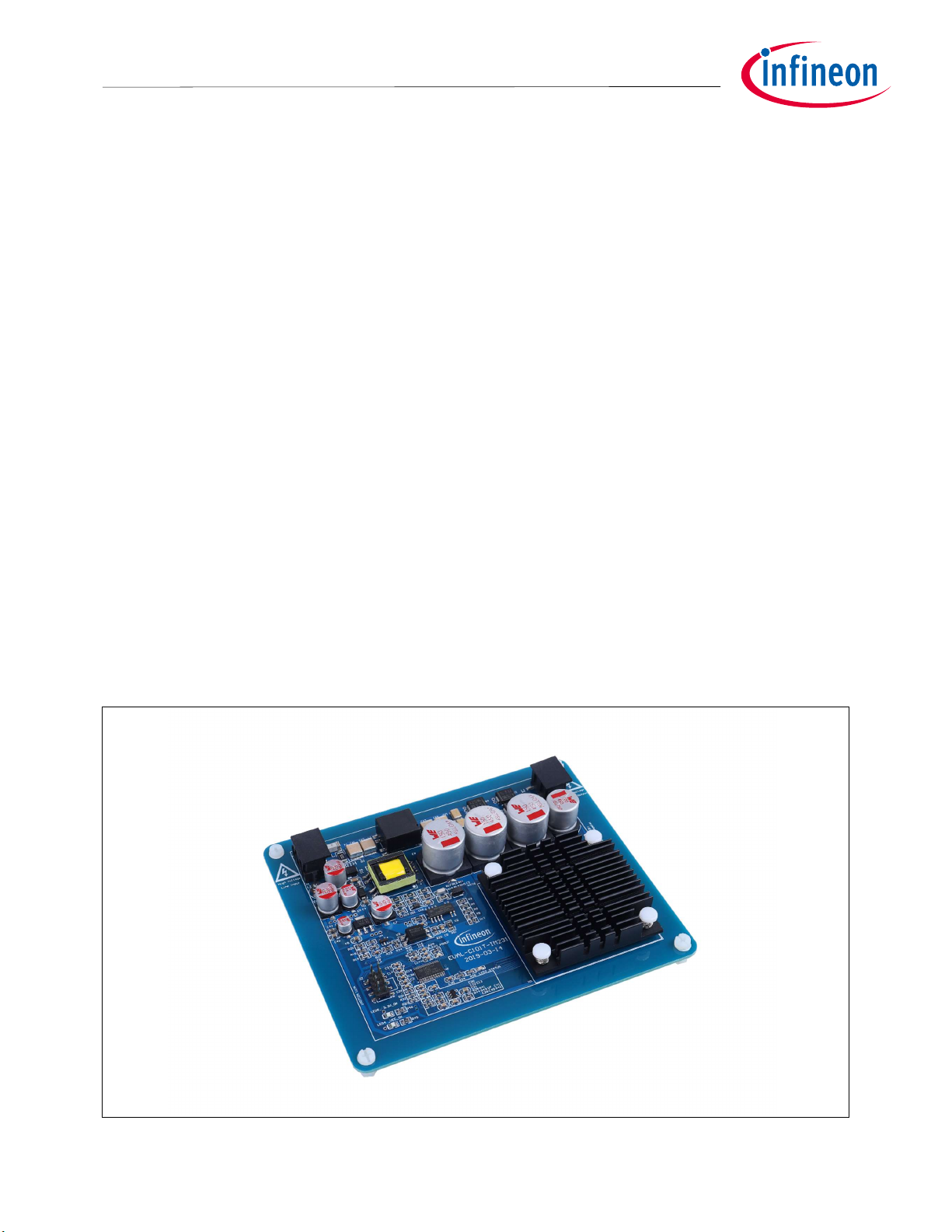
Figure 1 shows the evaluation board EVAL-C101T-IM231. This evaluation board includes an EMI filter and
IMC101T-T038 controller, Flyback power supply to provide 15V and 3.3V, and the CIPOSTM Micro IPM – IM231L6S1B.
Figure 1 Evaluation board of the EVAL-C101T-IM231
User manual 3 <Revision 1.0>
<2019-07-30>
Page 4

Motor Drive Evaluation Board Based On IMC101T
-T038 and IM231
-
L6S1B
Main features
EVAL-C101T-IM231 User manual
3 Main features
EVAL-C101T-IM231 is a complete evaluation board including IMC101T-T038 controller and a 3 phase Micro IPM
for motor control application. The kit demonstrates Infineon’s motion control IC and IPM technology for motor
drives.
The evaluation board characteristics are:
• Flat design
• All components are SMD and only placed on the top side
• Complete evaluation board for running any permanent magnet motor via sensor-less sinusoidal control
• Input voltage 160~265 VAC
• Maximum 180 W (with heatsink and F
• On board EMI filter
• Current sensing with single shunt
• Flyback power supply with 15 V, 3.3 V
• Over current protection
• Sensing of DC-link voltage
• Fault diagnostic output
• PCB is 130×110mm and has two layers with 35μm copper each
• RoHS complaint
Applications:
• fridge compressor
• Small home appliances
• Pumps
Main features of Motion Control IC (IMC101T-T038) are:
• MCE (Motion Control Engine) as ready-to-use solution for variable speed drives
• Field oriented control (FOC) for permanent magnet synchronous motor (PMSM)
• Space vector PWM with sinusoidal commutation and integrated protection features
• Current sensing via single or leg shunt
• Sensorless operation
• Various serial communication interfaces (UART, I2C, SPI)
• Multiple motor parameter support
• 3.3 V (default) or 5 V VDD power supply
• Flexible host interface options for speed commands: UART, I2C, SPI, PWM or analog signal
• Support for IEC 60335 (‘Class B’)
• Scalable package options
=6kHZ) motor power output
PWM
User manual 4 <Revision 1.0>
<2019-07-30>
Page 5
Motor Drive Evaluation Board Based On IMC101T
-T038 and IM231
-
L6S1B
Main features
EVAL-C101T-IM231 User manual
Main features of CIPOSTM Micro IPM-IM231-L6S1B are:
• 600 V 3-phase inverter including gate drivers & bootstrap function
• Low VCE(sat) TRENCHSTOP™ IGBT6
• Temperature monitor
• Accurate overcurrent shutdown (±5%)
• Fault reporting and programmable fault clear
• Advanced input filter with shoot-through protection
• Optimized dv/dt for loss and EMI trade offs
• Open-emitter for single and leg-shunt current sensing
• 3.3 V logic compatible
• Isolation 2000 VRMS, 1min
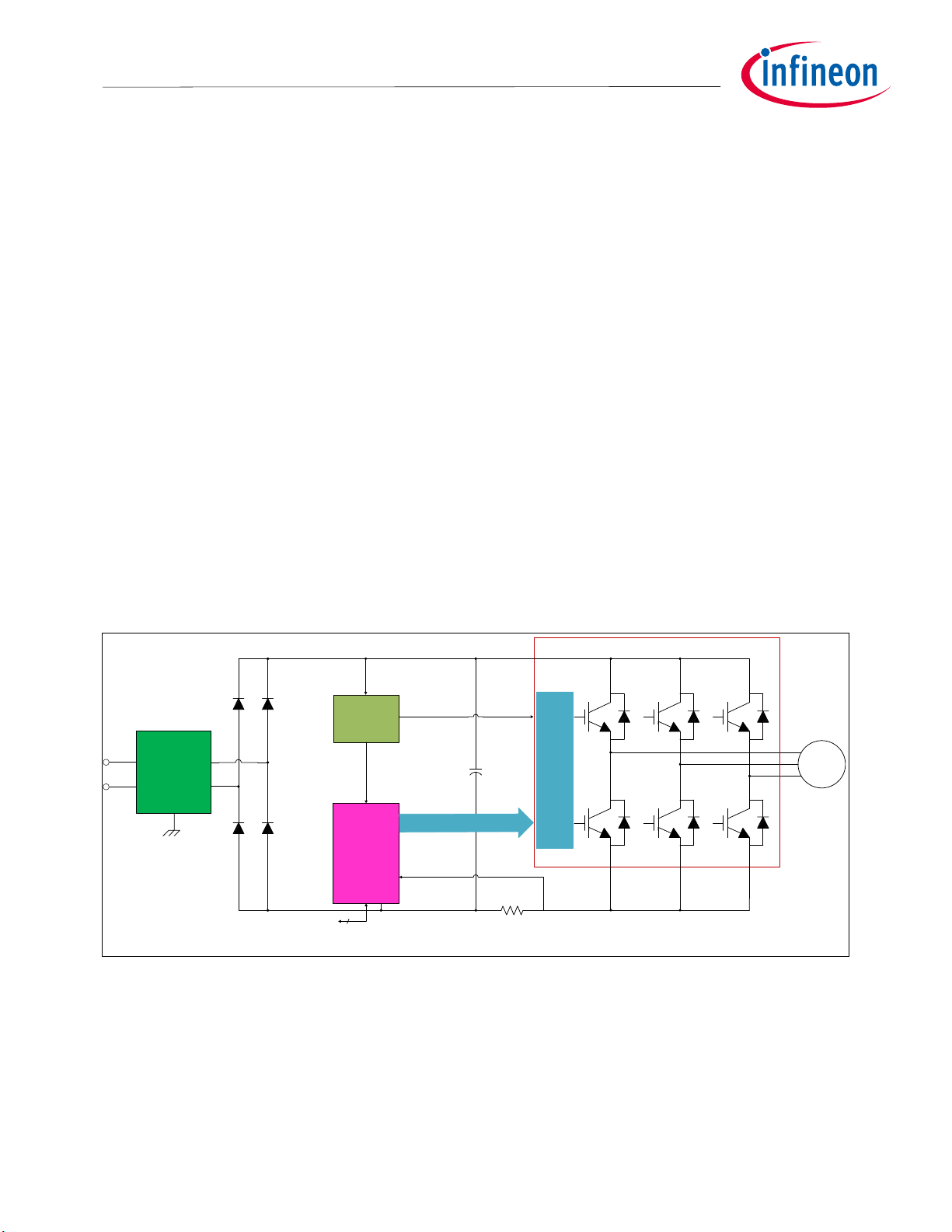
3.1 Key data
Figure 2 provides a typical application Block Diagram using the IMC101T-T038 with single shunt current sensing.
The IMC101T-T038 provides a built-in closed loop sensorless control algorithm using the unique flexible Motion
Control Engine (MCE) for permanent magnet motors. The MCE™ consists of a collection of control elements,
motion peripherals, a dedicated motion control sequencer and internal memory to map internal signal nodes.
IMC101T-T038 also employs a unique single shunt current reconstruction circuit in addition to leg shunt current
sensing circuit to eliminate additional analog/digital circuitry.
CIPOSTM Micro IPM
U
V
M
W
Line
Neutral
EMI Filter
&
FUSE
Earth
UART interface to Front Panel
V
BUS
CoolSET For
AUX Power
Supply
3.3V
IMC101T
-T038
15V
Inverter PWM
V
BUS
C
BUS
Shunt Sensor
HVIC
Figure 2 Typical Application Block Diagram of Evaluation Board with Single Shunt Current Sensing
User manual 5 <Revision 1.0>
<2019-07-30>
Page 6

Motor Drive Evaluation Board Based On IMC101T
-T038 and IM231
-
L6S1B
Main features
EVAL-C101T-IM231 User manual
Figure 3 provides pinout of the IMC101T-T038. The following drawings give the position of the functional pins
for the available packages.
HALL1/AIN4
VDC
IV/AHALL2-
REFV/AHALL2+/AIN7
REFU/AIN8
ISS/IU
NTC/AIN10
PARAM/HALL3/AIN11
VSS
VDD
PWMUL
PWMUH
PWMVL
PWMVH
PWMWL
PWMWH
LED
GK
TX1
1
2
3
4
5
6
7
8
IMC101T
9
10
11
12
13
14
15
16
17
18
19
T038
(Top View)
38
37
36
35
34
33
32
31
30
29
28
27
26
25
24
23
22
21
20
HALL2/AIN3
IW/AHALL1-/AIN2
REFW/AHALL1+/AIN1
VSP/AIN0
TX0
RX0
GPIO9
DUTYFREQ
GPIO8
GPIO7
DIR/GPIO6
PAR3/GPIO6
VDD
VSS
PAR2/GPIO4
PAR1/GPIO3
PAR0/GPIO2
PGOUT
RX1
Figure 3 Pinout of IMC101T-T038
Note: Refer to the datasheet for more detailed specifications of the pin type. Those pins with generic
naming (GPIO) can be used via scripting.
Note: Figure 4 provides Internal Electrical Schematic of the IM231-L6S1B micro IPM. Refer to data sheet of
the IM231-L6S1B for more detail information.
Figure 4 Internal electrical schematic
User manual 6 <Revision 1.0>
<2019-07-30>
Page 7

Motor Drive Evaluation Board Based On IMC101T
-T038 and IM231
-
L6S1B
Main features
3.9 A
EVAL-C101T-IM231 User manual
Table 2 depicts the important specifications of the evaluation board EVAL-C101T-IM231.
Table 2 EVAL-C101T-IM231 board specifications
Parameters Values Conditions / comments
Input
Voltage 220VAC
Lower AC input, less motor power
output(with Heatsink)
At 220 VAC input, Ta=25°C,
Current 1.9ARM
1
THS=80°C,F
=6kHz(with
PWM
Heatsink)
Output
At 220 VAC input, Ta=25°C,
Power(3 phases) 180W
THS=80°C,F
=6 kHz(with
PWM
Heatsink)
At 220 VAC input, Ta=25°C,
Phase Current 1.1A
RMS
THS=80°C, F
=6 kHz(with
PWM
Heatsink)
Thermal Resistance
R
thca
10.7℃/W
Heatsink Thermal Resistance
without Fan
DC Bus Voltage
DC Bus voltage 310 V Input 220VAC
DC Bus voltage Ripple 30 V C
=55uF @output power=180W
BUS
DC Bus Scaling 8.29 counts/v DC Bus sense Scaling
Current feedback
Inverter Current sensing resistors
RS1
Inverter Current Op-amp
Configuration
100 mΩ Single shunt
Inverting
Inverter Current Op-amp Gain 2.65
IMC101T-T038 Resolution 12-bit
Latency 1 PWM cycle
Protections
2
3-phase output current trip level
Temperature trip level Tc=100 °C
IMC101T-T038 internal current trip
level
peak
Configured by the resistors R41
Only valid for CIPOSTM with built in
NTC
0.875V Refer to MCEWizard Question 80
On board power supply
15V 15V+/-2% For CIPOS
TM
IPM driver
1
T
indicates the temperature of the heatsink’s base.
HS
2
For iMOTION™ IC IMC1xx, there are three types of Gatekill Input Source (Refer to section 5.5 or control board user manual for detail).
Please note that, if select comparator for Gatakill Input Source, the external Gatakill signal will be not used. And the leg I_Shunt will
be compared by the internal comparator with the “Gatekill Comparator Reference” value set in MCEWizard only.
User manual 7 <Revision 1.0>
<2019-07-30>
Page 8

Motor Drive Evaluation Board Based On IMC101T
-T038 and IM231
-
L6S1B
EVAL-C101T-IM231 User manual
Main features
Parameters Values Conditions / comments
3.3V 3.3V+/-2%
For IMC101T-T038 power supply,
Protection circuits
PCB characteristics
Material
FR4, 1.6mm thickness
Copper thickness = 1oz (35um)
Dimension 130mmx110mm PCB Size
System environment
Ambient temperature 25°C
3.2
The relationship between IO and F
for EVAL-C101T-IM231
PWM
Figure 5 the picture is showing the relationship between IO (3 phase output current) and PWM Frequency, The
curves can be used as a reference to output current capability of the evaluation board when you use it.
Io& F
1.6
1.4
1.2
1
0.8
Io Amp
0.6
0.4
0.2
0
0 5 10 15 20 25
PWM
@Tc=100
℃,Rthca=10.7℃/W For EVAL-C101T-IM231
6, 1.5
10, 1.17
15, 0.97
20, 0.92
fs kHZ
Figure 5 The relationship between Output Current and PWM Frequency
Note:
3.3
Tc measurement point refer to datasheet (section 11.1) of the IM231-L6S1B
Setting up the system
In order to run this evaluation board, the iMOTION™ Software Tools MCEDesigner and MCEWizard are also
required initially setup the system, as well as to control and fine-tune the system performance to match users
exact needs. Refer to 3.4 as well as MCEWizard and MCEDesigner documentation for more information.
User manual 8 <Revision 1.0>
<2019-07-30>
Page 9
Motor Drive Evaluation Board Based On IMC101T
-T038 and IM231
-
L6S1B
1. J1 -
AC Line connector
1
2
3
5
6
7
8
9
EVAL-C101T-IM231 User manual
Main features
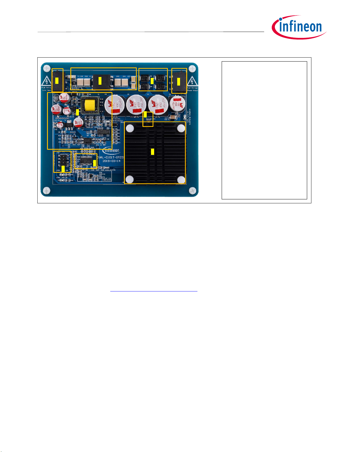
Figure 6 points out the functional groups on the top side of the EVAL-C101T-IM231 evaluation board.
2. EMI filter
4
3. Rectifier
4. J3 - Motor phase connector
5. Fly back power supply
6. IMC101T-T038 controller
7. CIPOSTM Micro IPM IM231L6S1B
8. J2 - iMOTIONTM Link
connector
9. Inverter shunt resistor
Figure 6 Functional groups of the EVAL-C101T-IM231 evaluation board’s top side
3.4
The user needs to assemble all the external hardware and ensures that all the connections are intact (includes
AC-Line connector, iMOTIONTM Link Tool and motor 3-phase output connector) When users get this EVALC101T-IM231 evaluation board, then they can start trying to run the motor system. By default the user’s
evaluation board has been burned in the software to IMC101T, please execute the step2 directly. Otherwise,
take the step1 and step2.
The iMOTION™ Development Tool installers for MCEDesigner and MCEWizard are available for download via
Infineon iMOTIONTM website http://www.infineon.com/iMOTION. All supported tools and software variants are
listed there. Please visit this page periodically to check for tool/software updates.
System debug process
User manual 9 <Revision 1.0>
<2019-07-30>
Page 10
Motor Drive Evaluation Board Based On IMC101T
-T038 and IM231
-
L6S1B
Output
s
EVAL-C101T-IM231 User manual
Main features
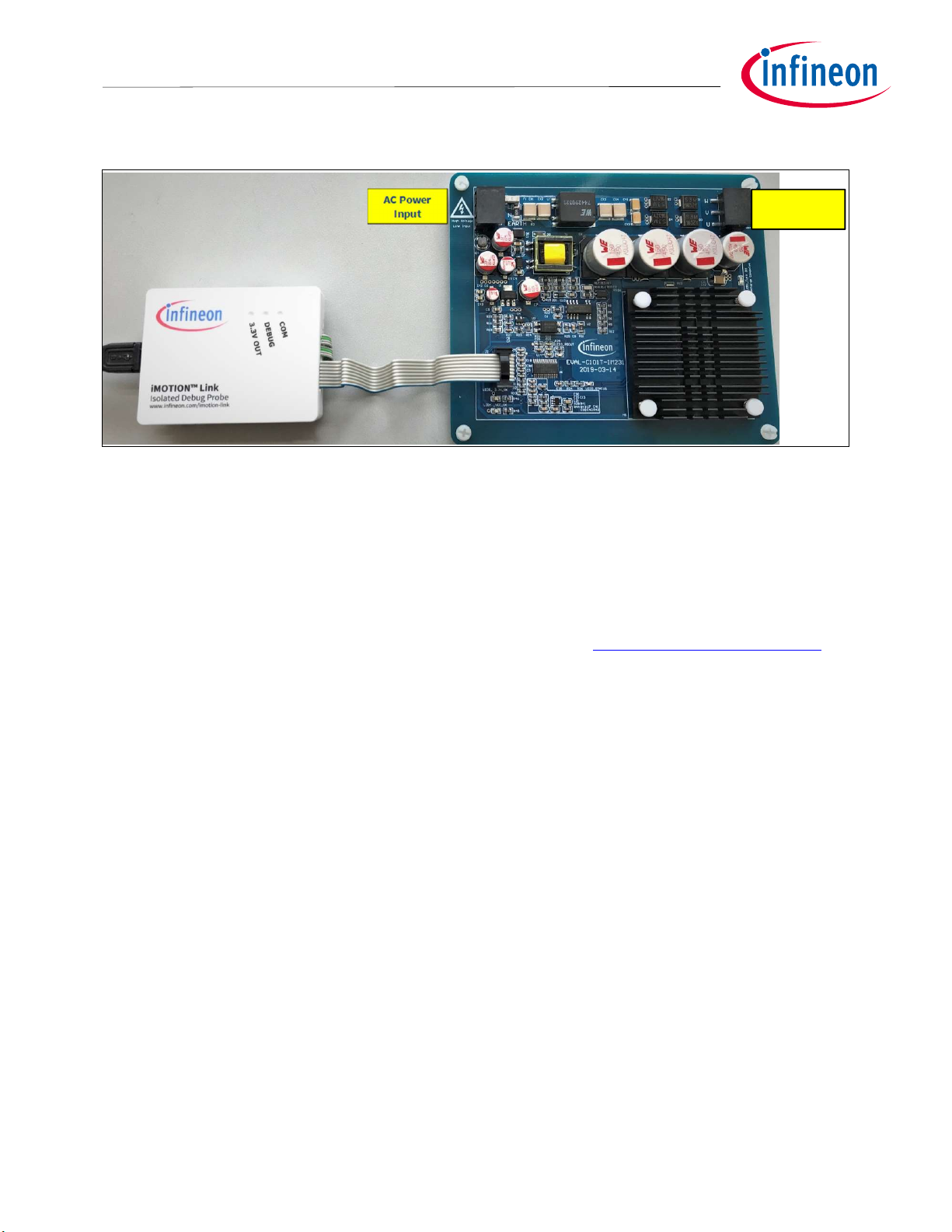
Figure 7 the picture is showing the application system connection.
Figure 7 System connection indication
Motor Phase
STEP1: Download Firmware to IMC101T
(1) Connect iMOTIONTM Link to J2.
(2) Power on system.
(3) Use MCEDesigner program firmware to IMC101T’s internal SRAM.
(4) Power off system.
Note:
The firmware version for IMC101T is from the Infineon website. http://www.infineon.com/iMOTION
STEP2: Tuning Motor
(1) Keep the iMOTIONTM Link Tool connect to J2.
(2) Use MCEWizard calculates motor hardware parameters and generate the parameters file (.txt).
(3) Power on system.
(4) Use MCEDesigner to program the parameters file (.txt) to the iMOTIONTM controller.
(5) Start running motor system.
3.5
MCEWizard setup overview
After installing the MCEWizard, the shortcut for MCEWizard appears on the Windows desktop. Double click the
shortcut to open the MCEWizard and configure the parameters for evaluation boards or motor. Figure 8 shows
the “Welcome Page” for MCEWizard, where the MADK control board or power board can be selected through
the pull-down list. Infineon keeps releasing new MADK controller and power boards. Therefore, it could happen
that some of the newest power boards are not pre-configured in the MCEWizard tool and cannot be selected
through the pull-down menu. In that case, the user should select any other power board (as similar as possible)
and follow the MCEWizard setup steps by entering the parameter values which are specific to the chosen board.
Make sure both “I have modified the circuit board” and “Enable advanced question” checkmarks are selected.
Please refer to the User Manual of the corresponding power board for additional information.
User manual 10 <Revision 1.0>
<2019-07-30>
Page 11

Motor Drive Evaluation Board Based On IMC101T
-T038 and IM231
-
L6S1B
Main features
EVAL-C101T-IM231 User manual
After selecting the MADK control and the power board, start the MCEWizard system setup procedure by clicking
the “Next” button in the right bottom corner as shown in Figure 8.
Figure 8 Welcome Page of MCEWizard
iMOTION™ MADK system enables users to easily test different combination of control and power board with
their motors. User should be familiar with the system level parameters which are related to the motor used.
There are very limited numbers of parameters which are specific to the control board or power board hardware.
Table 3 provides the MCEWizard setup overview for hardware related parameters. Similar tables will be
available in each power board’s User Manual. Combination of this table and the corresponding table of the
power board provides enough information to setup the MADK-based motor drive system in shortest time.
Table 3 MCEWizard setup overview table
Page Parameter Value Comment
Welcome Page Power Board selecting MADK power board name If no, select EVAL-M1-
05-65D to modify
Options Page Motor 1 Shunt Configuration 100mΩ Single shunt
Hall Sense Configuration Refer to the Motor Parameters None Hall by default
Script Function Options Enable or Disable Disable by default
Question 3 Controller Supply Voltage 3.3V
Question 19 Max DC Bus Voltage 420V
Question 23 DC Bus Sensing High Resistor 2MΩ
Question 24 DC Bus Sensing Low Resistor Refer to control board user manual 13.3kΩ by default
Question 63 GateSense Low-Side Devices High is true High is true by default
Question 64 GateSense High-Side Devices High is true High is true by default
Script Edit
Page
Script Configuration ADC pin and GPIO pin Configuration Refer to the “Script
For MCE 2.0 User
Guide”
User manual 11 <Revision 1.0>
<2019-07-30>
Page 12

Motor Drive Evaluation Board Based On IMC101T
-T038 and IM231
-
L6S1B
Main features
EVAL-C101T-IM231 User manual
Page Parameter Value Comment
Script Coding Script File Operation and Script
Text Edit
Refer to the
“Reference Manual”
and the “Application
Guide”
Note: Please refer to the following link for more detailed information about Edit Script File.
1. Reference Manual: Page 44-58:2.5 Script Engine
-Infineon MCESW RM UM v01_01 EN.pdf
2. Application Guide
-Infineon AN2018 27_How_to_Use_iMOTION_Script_Language AN
After all the MCEWizard questions are answered, the “Verify & Save Page” will be shown as in Figure 9
Figure 9 Verify and Save page for MCEWizard
Click “Calculate” button and “Export to Designer File (.txt)” button to save the parameter file which will be used
by the MCEDesigner in the next steps.
User manual 12 <Revision 1.0>
<2019-07-30>
Page 13

Motor Drive Evaluation Board Based On IMC101T
-T038 and IM231
-
L6S1B
Main features
EVAL-C101T-IM231 User manual
3.6 MCEDesigner setup overview
After installing MCEDesigner installer, there is a shortcut for MCEDesigner on Windows desktop. Double click
the shortcut to open MCEDesigner and then open “IMC101T_xx.irc” file.
Figure 10 MCEDesigner’s Main Display for EVAL-M1-101T
To program system drive parameters into IMC101T-T038, please click “Tools” menu and select “Programmer”
in the pull down list. The pop-up window “Program IMC controller” will show up as in Figure 11. Click on the
“Program Parameters” radio button (this is the default option), and then select the Drive System Parameter file
created using MCEWizard by clicking on “Browse”. Finally, click on the “Start” button to program the parameter
file into the IMC101T-T038 IC.
Figure 11 “Program IMC Controller” pop-up window
After Drive System Parameter file has been programmed into IMC101T controller, and the motor drive system is
powered, the MCEDesigner can be used to start/stop the motor, display motor current traces, change the motor
User manual 13 <Revision 1.0>
<2019-07-30>
Page 14

Motor Drive Evaluation Board Based On IMC101T
-T038 and IM231
-
L6S1B
Main features
EVAL-C101T-IM231 User manual
speeds, modify drive parameters and many other functions. Please refer to the MCEDesigner documentation
for more details.
To program new firmware and Drive System Parameter into IMC101T-T038, please click “Tools” menu and
select “Programmer” in the pull down list. The pop-up window “Program IMC controller” will show up as in
Figure 12. Click on the “Program Firmware and Parameter” radio button, and select the Drive System
Parameter file created using MCEWizard by clicking on the “Browse” button on the row of “Program Parameter
File”, and then select the firmware file by clicking on the “Browse” button on the row of “Program Firmware
File”. Finally, click on the “Start” button to program the parameter file into the IMC101T-T038 IC.
Figure 12 Program Firmware and Parameter in “Program IMC Controller” pop-up window
Note: All latest firmware file for different type of iMOTIONTM control ICs are available for download via
Infineon iMOTION
TM
website http://www.infineon.com/iMOTION.
User manual 14 <Revision 1.0>
<2019-07-30>
Page 15

Motor Drive Evaluation Board Based On IMC101T
-T038 and IM231
-
L6S1B
Pin assignments
AC line input(160 V
265 V)
Connected to motor phase U
2 V Connected to motor
phase V
Connected to motor phase W
EVAL-C101T-IM231 User manual
4 Pin assignments
General information about the connectors of the EVAL-C101T-IM231 evaluation board is described below.
Table 4 provides the pin assignments of the J2.
Table 4 J2-iMOTION Link interface
S. No. Pin Details
1 TXD0 Output, Transmit data from IMC101T
2 RXD0 Input, Receive data to IRMCF188
3 +3.3V On board 3.3 V supply
4 GND Ground
5 GND Ground
6 +3.3V On board 3.3 V supply
7 RXD1 Input, Receive data to IMC101T
8 TXD1 Output, Transmit data from IMC101T
Table 5 provides the pin assignments of the AC line connector J1.
Table 5 J1- AC Line connector
S. No. Pin Details
1 L
2 N AC neutral input
3 EARTH Earth ground
Table 6 denotes the details of the motor side connector J3.
Table 6 J3-Motor side connector
S. No. Pin Details
1 U
3 W
~
User manual 15 <Revision 1.0>
<2019-07-30>
Page 16

Motor Drive Evaluation Board Based On IMC101T
-T038 and IM231
-
L6S1B
Schematics and Layout
EVAL-C101T-IM231 User manual
5 Schematics and Layout
To meet individual customer requirements and make the EVAL-C101T-IM231 evaluation board a basis for
development or modification, all necessary technical data like schematics, layout and components are
included in this chapter.
5.1 EMI filter circuit
Figure 13 depicts the schematic from the AC line input connector J1 to the rectified DC bus voltage. This
circuitry includes a passive EMI filter consisting of elements CX1, CX2, L1, CX3, CX4, CY1 and CY2. D1, D2, D3, D4
rectifier block, and reducing conduct loss in steady state.
F1
3A 250V SMD
L
N
R3
1Mohm 1/2W 1%
CX1
4.7nF 250VA C SMD
EARTH
WE691709710303-SMT
J1
EARTH
CX2
5
6
1
10
L1
4.7nF 250VA C SMD
CX3
4.7nF 250VA C SMD
WE744290321 3.25A 0.32mH -SMD
CX4
4.7nF 250VA C SMD
CY1
470pF 250VAC SMD
EARTH
CY2
470pF 250VAC SMD
D2
D1
D4
CS3K 3A 800V-DO214AB
D3
Figure 13 The schematic for AC/DC section and EMI of the EVAL-C101T-IM231 evaluation board
User manual 16 <Revision 1.0>
<2019-07-30>
Page 17

Motor Drive Evaluation Board Based On IMC101T
-T038 and IM231
-
L6S1B
Schematics and Layout
EVAL-C101T-IM231 User manual
5.2 Inverter section using CIPOSTM Micro IPM
Inverter section are implemented using the CIPOSTM Micro IPM as sketched in Figure 14. The CIPOSTM module
includes 600 V 3-phase inverter including gate drivers & bootstrap function, and low VECTRENCHSTOPTM IGBT6.
The three capacitors C20, C27 and C32 are used as bootstrap capacitors to provide the necessary floating
supply voltages V
, V
BS1
BS2
WE691709710303-SMT
J3
1
2
3
GND
and V
U
V
W
respectively.
BS3
C12
10nF 630V
DCBUS
GND
Isense+
RS3 100mohm 2W 1%
C11
10nF 630V
IM231-L6S1B
U5
17
V+
18
VS1/U
21
VS2/V
23
VS3/W
19
VR1
20
VR2
22
VR3
2.2uF 25V
GND
GND
GND
C20
U
C23 1uF 25V
PWMUH
PWMUL
GK
C27 2.2uF 25V
V
C28 1uF 25V
PWMVH
PWMVL
VTH
C32 2.2uF 25V
W
C34 1uF 25V
PWMWH
PWMWL
GND
VCC
VCC
VCC
ITRIP
C38
1nF 16V
2
VB1
3
VCC1
4
HIN1
5
LIN1
6
RFE
7
VB2
8
VCC2
9
HIN2
10
LIN2
11
VTH
12
VB3
13
VCC3
14
HIN3
15
LIN3
1
COM
16
ITRIP
VCC
HIN
LIN
COM
VCC
HIN
LIN
COM
VCC
HIN
LIN
COM
VB
HO
VS
LO
VB
HO
VS
LO
VB
HO
VS
LO
Figure 14 The schematic of 3-phase inverter section using CIPOSTM Micro IPM on the EVAL-C101T-
IM231 evaluation board
User manual 17 <Revision 1.0>
<2019-07-30>
Page 18

Motor Drive Evaluation Board Based On IMC101T
-T038 and IM231
-
L6S1B
EVAL-C101T-IM231 User manual
Schematics and Layout
5.3
Figure 15 shows the schematic of EVAL-C101T-IM231 evaluation board with IMC101T-T038 controller.
IMC101T-T038 Schematic Overview
Figure 15 The schematics for the EVAL-C101T-IM231 evaluation board
User manual 18 <Revision 1.0>
<2019-07-30>
Page 19

Motor Drive Evaluation Board Based On IMC101T
-T038 and IM231
-
L6S1B
Schematics and Layout
EVAL-C101T-IM231 User manual
5.4 Auxiliary power supply
Figure 16 depicts the schematic of the auxiliary power supply available on the EVAL-C101T-IM231 board. The
circuit includes the latest CoolSET 5 of Infineon and fly back topology, directly output 15V and 3.3V. VCC is
connected to the gate drivers inside the CIPOS™ IPM.
DCBUS
C6
1000pF 16V
GND
R11
3M 1/4W
R13
3M 1/4W
R17
3M 1/4W
R22
62Kohm 1/4W 1%
R10
15M 1/4W
R14
15M 1/4W
R18
15M 1/4W
C10
0.1uF 25V
US1M-E3/61T-1A/1000V
D8
R15
DIO FRD 700mA 200V
4R7 1/10W
ZD1
MMSZ5251B-7-F-22V 500mW
GND
C2
1nF 630V
D6
E7 25V 100uF 8*6.5 SMD
U2
7
Drain
8
Drain
9
NC
10
GATE
11
VCC
12
GND
ICE5GR4780AG
Drain
Drain
VERR
CS
FB
VIN
R9
68k 1/4W
T1
EPC13 5-5 SMT
1
2
3
4
5
6
5
4
3
2
1
C1 4700pF 100V
6
SS2H10-E 2A/100V
7
BYS10-45-E3/TR3-1.5A/45V
9
10
5.1R 1/4WRS1
C9
2.2nF 16V
D5
D7
E5
10V 220uF 6*7.7 SMD
GND
U3
SFH617A-3X007
R25
3 4
510Kohm 1/8W 1%
R7 510kohm 1/4W 5%
+15V
E3
25V 220uF 8*10.5 SMD
+6V
C4
10uF 10V
R19
0ohm 1/8W 1%
12
L2
2.2uH 2.5A SMD
U1
IFX1117-ME V33
Vin Vout
GND
SGND
R24
820R 1/10W 1%
E4
25V 220uF 8*10.5 SMD
SGND
E6
6.3V 100uF 5*5.5 SMD
R20
1.5Kohm 1/8W 1%
22K 1/10WR21
C7
1nF 16V
U4
TL431DBZR
SGND
C8
220nF 16V
C42
10uF 25V
VCC
VCC
C43
10uF 25V
+3.3V
C5
10uF 10V
R16
48.7K 1/10W 1%
R23
9.76K 1/10W 1%
Figure 16 Power supply section of the EVAL-C101T-IM231 evaluation board
5.5 Inverter over current protection circuit
Figure 17 shows the Inverter over current protection circuitry. The open collector output of comparator U7 is
pulled up to 3.3V by resistor R42.
+3.3V
R41 7.5Kohm 1/8W 1%
GND
R42
1Kohm 1/8W 5%
4
ITRIP
LM397
VCC
U7
5 2
C41
10uF 16V
1
3
C39
4700pF 16V
ITRIP: [(3.3V * 1/ 8.5)+0.005] / 0.1= 3.9A peak
GND
Figure 17 Inverter section over current protection circuit of the EVAL-C101T-IM231 evaluation board
The comparator threshold can be set through the voltage divider provided by resistors R41 and R43. By default
for single shunt application, R41 is 7.5kΩ and R43 is 1KΩ.
Ω
.∗
Itrip_
Inverter
=
.ΩΩ
Ω
=3.9A
C40
4700pF 16V
R43 1Kohm 1/8W 1%
R44 1Kohm 1/8W 1%
GND
Isense+
User manual 19 <Revision 1.0>
<2019-07-30>
Page 20

Motor Drive Evaluation Board Based On IMC101T
-T038 and IM231
-
L6S1B
Schematics and Layout
EVAL-C101T-IM231 User manual
5.6 PCB Layout
The layout of this board can be used for different voltage or power classes of power board. The PCB has two
electrical layers with 35µm copper by default and its size is 130 mm × 110 mm. The PCB board thickness is
1.6mm. Get in contact with our technical support team to get more detailed information and the latest Gerberfiles.
Figure 18 illustrates the top assembly print of the evaluation board.
Figure 18 Top overlay print of the EVAL-C101T-IM231 evaluation board
Figure 19 depicts the bottom assembly print of the evaluation board.
Figure 19 Bottom overlay print of the EVAL-C101T-IM231 evaluation board
User manual 20 <Revision 1.0>
<2019-07-30>
Page 21

Motor Drive Evaluation Board Based On IMC101T
-T038 and IM231
-
L6S1B
Schematics and Layout
EVAL-C101T-IM231 User manual
The top layer routing of the PCB is provided in Figure 20.
Figure 20 Top layer routing of the EVAL-C101T-IM231
Figure 21 illustrates the bottom layer routing of the PCB.
Figure 21 Bottom layer routing of the EVAL-C101T-IM231
User manual 21 <Revision 1.0>
<2019-07-30>
Page 22

Motor Drive Evaluation Board Based On IMC101T
-T038 and IM231
-
L6S1B
Bill of Materials of EVAL
-
C101T
-
IM231
.
EVAL-C101T-IM231 User manual
6 Bill of Materials of EVAL-C101T-IM231
Table 7 provides the complete bill of materials for the EVAL-C101T-IM231 board.
Table 7 Bill of materials
Qty
No.
1 1 CAP CER 4700PF 100V X7R 1206 C1 885012208110 Wurth Electronics Inc.
2 1
3 5 CAP CER 4700PF 10V X7R 0603
4 2 CAP CER 10UF 10V X5R 0805 C4, C5 885012107010 Wurth Electronics Inc.
5 1
6 1
7 1 CAP CER 0.22UF 16V X7R 0603 C8 885012206048 Wurth Electronics Inc.
8 1 CAP CER 2200PF 16V NP0 0805 C9 885012007023 Wurth Electronics Inc.
9 1 CAP CER 0.1UF 25V X7R 0805 C10 885012207072 Wurth Electronics Inc.
10 2 CAP CER 10000PF 630V C0G 1812 C11, C12 C4532C0G2J103J160KA TDK Corporation
11 5 CAP CER 0.1UF 10V X7R 0603
12 3 CAP CER 2.2UF 25V X5R 0805
13 1 CAP CER 10000PF 10V X7R 0603 C22 885012206014 Wurth Electronics Inc.
14 3 CAP CER 1UF 25V X5R 0805
15 3 CAP CER 2200PF 10V NP0 0603
16 1 CAP CER 220PF 10V X7R 0603 C30 885012206004 Wurth Electronics Inc.
17 1 CAP CER 1000PF 16V NP0 0805 C38 885012007021 Wurth Electronics Inc.
18 2 CAP CER 4700PF 16V X7R 0805 C39, C40 885012207037 Wurth Electronics Inc.
19 1 CAP CER 10UF 16V X5R 0805 C41 885012107014 Wurth Electronics Inc.
20 2 CAP CER 10UF 25V X5R 0805 C42, C43 C2012X5R1E106K085AC TDK Corporation
21 4 CX 4.7nF 250VAC-SMD
22 2 CY 470pF 250VAC SMD CY1, CY2 885352211001 Wurth Electronics Inc.
23 2
24 2
Part description Designator Part Number Manufacturer
CAP CER 1000PF 630V C0G/NP0
1206
CAP CER 1000PF 16V C0G/NP0
0603
CAP CER 1000PF 16V C0G/NP0
0603
DIODE GEN PURP 800V 3A
DO214AB
DIODE SCHOTTKY 100V 2A
DO220AA
C2 885342008005 Wurth Electronics Inc.
C3, C17,
C18, C21,
C36
C6 885012006029 Wurth Electronics Inc.
C7 885012006029 Wurth Electronics Inc.
C13, C14,
C15, C16,
C26
C20, C27,
C32
C23, C28,
C34
C24, C25,
C35
CX1, CX2,
CX3, CX4
D1, D2, D3,
D4
D5 SS2PH10-M3/84A
885012206012 Wurth Electronics Inc.
885012206020 Wurth Electronics Inc.
885012107016 Wurth Electronics Inc.
885012107015 Wurth Electronics Inc.
885012006015 Wurth Electronics Inc.
885352214001 Wurth Electronics Inc.
S3K-E3/9AT
Vishay Semiconductor
Diodes Division
Vishay Semiconductor
Diodes Division
User manual 22 <Revision 1.0>
<2019-07-30>
Page 23

Motor Drive Evaluation Board Based On IMC101T
-T038 and IM231
-
L6S1B
Bill of Materials of EVAL
-
C101T
-
IM231
.
RES SMD 13.3K OHM 0.1% 1/8W
EVAL-C101T-IM231 User manual
Qty
No.
25 2
26 2
27 2
28 1 CAP AL 15uF 450V 16*17 SMD E1, E2, E8 865061463005 Wurth Electronics Inc.
29 1
30 1
31 1
32 2 CAP AL LD 25V 100uF M 8*6.5 E7 865080449011 Wurth Electronics Inc.
33 2 CAP AL 15uF 450V 12.5*14 SMD E9 865061462004 Wurth Electronics Inc.
34 3 FUSE BOARD MOUNT 250V 3.0A F1 F6632DKR-ND Littelfuse Inc.
35 1
36 7
37 1 CMC 320UH 3.25A 2LN SMD L1 744290321 Wurth Electronics Inc.
38 1
39 5 LED RED CLEAR 0805 SMD LED1 150080RS75000 Wurth Electronics Inc.
40 1 LED RED CLEAR 0603 SMD LED2 150060RS75000 Wurth Electronics Inc.
41 2 LED GREEN CLEAR 0603 SMD LED3 150060GS75000 Wurth Electronics Inc.
42 2 LED GREEN CLEAR 0805 SMD
43 3 RES SMD 100Kohm 1/2W 2010 R1, R4 RMCF2010JT300R Yageo
44 2 RES SMD 500Kohm 1/8W 0805
45 2 RES SMD 1Mohm 1/2W 2010 R3 RT2010DKE071ML Yageo
46 2 RES SMD 510Kohm 1/4W 1206 R7 RC0603JR-077K68L Yageo
47 6 RES SMD 1/4W 68kohm F 1206 R9 HVCB0805FKC1M00
48 4 RES SMD 1/4W 15M 1206
49 1 RES SMD 1/4W 3M F 1206
Part description Designator Part Number Manufacturer
DIODE GEN PURP 1KV 1A
DO214AC
DIODE SCHOTTKY 45V 1.5A
DO214AC
DIO FRD 700mA 200V SOD-1232P 25nS SMD ROHM
CAP AL LD 25V 220uF M 8*10.5
SMD
CAP AL LD 10V 220uF M 6.3*7.7
SMD
CAP AL LD 6.3V 100uF M 5*5.5
SMD
WE WR-TBL Serie 7097-5.0mm3P SMT
CONN HEADER SMD 8POS
2.54MM
FIXED IND 2.2UH 2.5A 71 MOHM
SMD
D6 US1M-E3/61T
D7 BYS10-45-E3/TR3
D8 RF071MM2STR Rohm Semiconductor
E3, E4 865080453013 Wurth Electronics Inc.
E5 865080245009 Wurth Electronics Inc.
E6 865080142007 Wurth Electronics Inc.
J1, J3 691709710303 Wurth Electronics Inc.
J2 61000821121 Wurth Electronics Inc.
L2 744773022 Wurth Electronics Inc.
LED4,
LED5
R2, R5, R6,
R8
R10, R14,
R18
R11, R13,
R17
150080GS75000 Wurth Electronics Inc.
RNCF0805BTE500K
RC0603FR-074K87L Yageo
RC0805FR-074K99L Yageo
Vishay Semiconductor
Diodes Division
Vishay Semiconductor
Diodes Division
Stackpole Electronics
Inc
Stackpole Electronics
Inc.
50 1
51 1
User manual 23 <Revision 1.0>
<2019-07-30>
0805
RES SMD 1/10W4.7ohm F 0603
R12 RT0805BRD0713K3L Yageo
R15 RC0603JR-074R7L Yageo
Page 24

Motor Drive Evaluation Board Based On IMC101T
-T038 and IM231
-
L6S1B
Bill of Materials of EVAL
-
C101T
-
IM231
.
RES SMD 4.87Kohm 1/10W 0603
RES SMD 13.8Kohm 1/10W 0603
IC MOTOR CONTROLLER
3V-
5.5V
IC COMPARATOR VOLT SGL
EVAL-C101T-IM231 User manual
Qty
No.
52 1
53 1
54 2
55 4
56 2
57 1
58 1
59 1
60 1
Part description Designator Part Number Manufacturer
RES SMD 1/10W 48.7Kohm F 0805
RES SMD 0ohm 1/8W 0805
RES SMD 1.5Kohm 1/8W 0805
RES SMD 1/10W 22Kohm F 0603
RES SMD 58.3Kohm 1/4W 1206
RES SMD 1/10W 9.76Kohm F 0603
RES SMD 1/10W 820ohm F 0603
RES SMD 510Kohm 1/8W 0805
RES SMD 3.1Kohm 1/10W 0603 5%
R16, R34 RC0805FR-074K87L Yageo
R19 RC0805JR-070RL Yageo
R20 RC0805JR-071K5L Yageo
R21 RC0603FR-0722KL Yageo
R22 TNPW120658K3BEEA Vishay Dale
R23 RC0603FR-079K76L Yageo
R24 RC0603JR-07820RL Yageo
R25 RC0805JR-07510KL Yageo
R26 M55342K12B3E10RWSV Vishay Dale
61 1
62 1
63 1
64 1
65 1
66 2
68 2
70 1
71 1
72 1
73 1
74 1
75 2
76 1
77 1
78 1
79 1
80 2
1%
5%
RES SMD 47ohm 1/10W 0603 5%
RES SMD 10Kohm 1/10W 0603 1%
RES SMD 100ohm 1/10W 0603 1%
RES SMD 2Kohm 1/10W 0603 1%
RES SMD 7.5Kohm 1/8W 0805
RES SMD 1Kohm 1/8W 0805
RES SMD 15Kohm 1/8W 0805
RES SMD 9.1Kohm 1/8W 0805
RES SMD 1/4W 3ohm F 1206
RES 0.1 OHM 1% 1W 2512
EPC13 5-5 SMT
IC REG LINEAR 3.3V 1A SOT223-4
125KHZ OFFLINE 800V 4.7 DSO12
OPTOISOLATOR 5.3KV TRANS
4SMD
IC VREF SHUNT ADJ SOT23-3
CIPOS MICRO IPM
R28 RT0603BRD074K87L Yageo
R29 RT0603BRD0713K8L Yageo
R30 RT0603BRD0747RL Yageo
R31 RT0603DRD0710KL Yageo
R32 RT0603DRD07100RL Yageo
R33 RC0603FR-072KL Yageo
R41 RT0805BRD077K5L Yageo
R43, R44,
R42
R45 RT0805BRD0715KL Yageo
R46 RC0805JR-079K1L Yageo
RS1 RC1206FR-073RL Yageo
RS3 RL2512FK-070R1L Yageo
T1
U1 IFX1117MEV33HTMA1 Infineon Technologies
U2 ICE5GR4780AGXUMA1 Infineon Technologies
U3 SFH617A-3X007T
U4 TL431IDBZR Texas Instruments
U5 IM231L6S1BALMA1-ND Infineon Technologies
RT0805BRD071KL Yageo
Vishay Semiconductor
Opto Division
81 1
82 1
83 1
User manual 24 <Revision 1.0>
<2019-07-30>
TSSOP-38
SOT23-5
DIODE ZENER 22V 500MW SOD123
U6 IMC101TT038XUMA1 Infineon Technologies
U7 LM397MF/NOPB Texas Instruments
ZD1 MMSZ5251B-7-F Diodes Incorporated
Page 25

Motor Drive Evaluation Board Based On IMC101T
-T038 and IM231
-
L6S1B
Reference
EVAL-C101T-IM231 User manual
7 Reference
[1] Datasheet of Infineon-IMC100-DS-v01_03-EN
[2] Datasheet of Infineon-IM231-L6S1B_T2B-DS-v02_00-EN
[3] 2018-11_AN2018-36_EVAL-M1-IM231-A User Manual_V1.0_EN
Note: Above all reference materials are available for download on Infineon’s website
http://www.infineon.com/iMOTION
User manual 25 <Revision 1.0>
<2019-07-30>
Page 26

Motor Drive Evaluation Board Based On IMC101T
-
T038 and IM231
-
L6S1B
Version number
EVAL-C101T-IM231 User manual
Revision History
Revision History
Major changes since the last revision
Revision Date Revision description
1.0 2019-07-30 First release
User manual 26 <Revision 1.0>
<2019-07-30>
Page 27

EasyPIM™,
ISOFACE™, IsoPACK™,
OptiMOS™, ORIGA™, POWERCODE™, PRIMARION™, PrimePACK™,
TEMPFET™,
manual
Trademarks of Infineon Technologies AG
AURIX™, C166™, CanPAK™, CIPOS™, CoolGaN™, CoolMOS™, CoolSET™, CoolSiC™, CORECONTROL™, CROSSAVE™, DAVE™, DI-POL™, DrBlade™,
EconoBRIDGE™, EconoDUAL™, EconoPACK™, EconoPIM™, EiceDRIVER™, eupec™, FCOS™, HITFET™, HybridPACK™, Infineon™,
i-Wafer™, MIPAQ™, ModSTACK™, my-d™, NovalithIC™, OmniTune™, OPTIGA™,
PrimeSTACK™, PROFET™, PRO-SIL™, RASIC™, REAL3™, ReverSave™, SatRIC™, SIEGET™, SIPMOS™, SmartLEWIS™, SOLID FLASH™, SPOC™,
thinQ!™, TRENCHSTOP™, TriCore™.
Trademarks updated August 2015
Other Trademarks
All referenced product or service names and trademarks are the property of their respective owners.
Edition <2019-07-30>
Published by
Infineon Technologies AG
81726 Munich, Germany
© 2019 Infineon Technologies AG.
All Rights Reserved.
Do you have a question about this
document?
Email: erratum@infineon.com
AN2019_09 EVAL-C101T-IM231 User
Document reference
IMPORTANT NOTICE
The information contained in this application note
is given as a hint for the implementation of the
product only and shall in no event be regarded as a
description or warranty of a certain functionality,
condition or quality of the product. Before
implementation of the product, the recipient of this
application note must verify any function and other
technical information given herein in the real
application. Infineon Technologies hereby
disclaims any and all warranties and liabilities of
any kind (including without limitation warranties of
non-infringement of intellectual property rights of
any third party) with respect to any and all
information given in this application note.
The data contained in this document is exclusively
intended for technically trained staff. It is the
responsibility of customer’s technical departments
to evaluate the suitability of the product for the
intended application and the completeness of the
product information given in this document with
respect to such application.
For further information on the product, technology,
delivery terms and conditions and prices please
contact your nearest Infineon Technologies office
(www.infineon.com).
Please note that this product is not qualified
according to the AEC Q100 or AEC Q101 documents
of the Automotive Electronics Council.
WARNINGS
Due to technical requirements products may
contain dangerous substances. For information on
the types in question please contact your nearest
Infineon Technologies office.
Except as otherwise explicitly approved by Infineon
Technologies in a written document signed by
authorized representatives of Infineon
Technologies, Infineon Technologies’ products may
not be used in any applications where a failure of
the product or any consequences of the use thereof
can reasonably be expected to result in personal
injury.
 Loading...