

Infineon EVAL AUDIO MA12040 Quick Start Manual

QUICK START GUIDE
Class D Audio Team
March 2019
EVAL_AUDIO_MA12040
Product overview and features
Overview
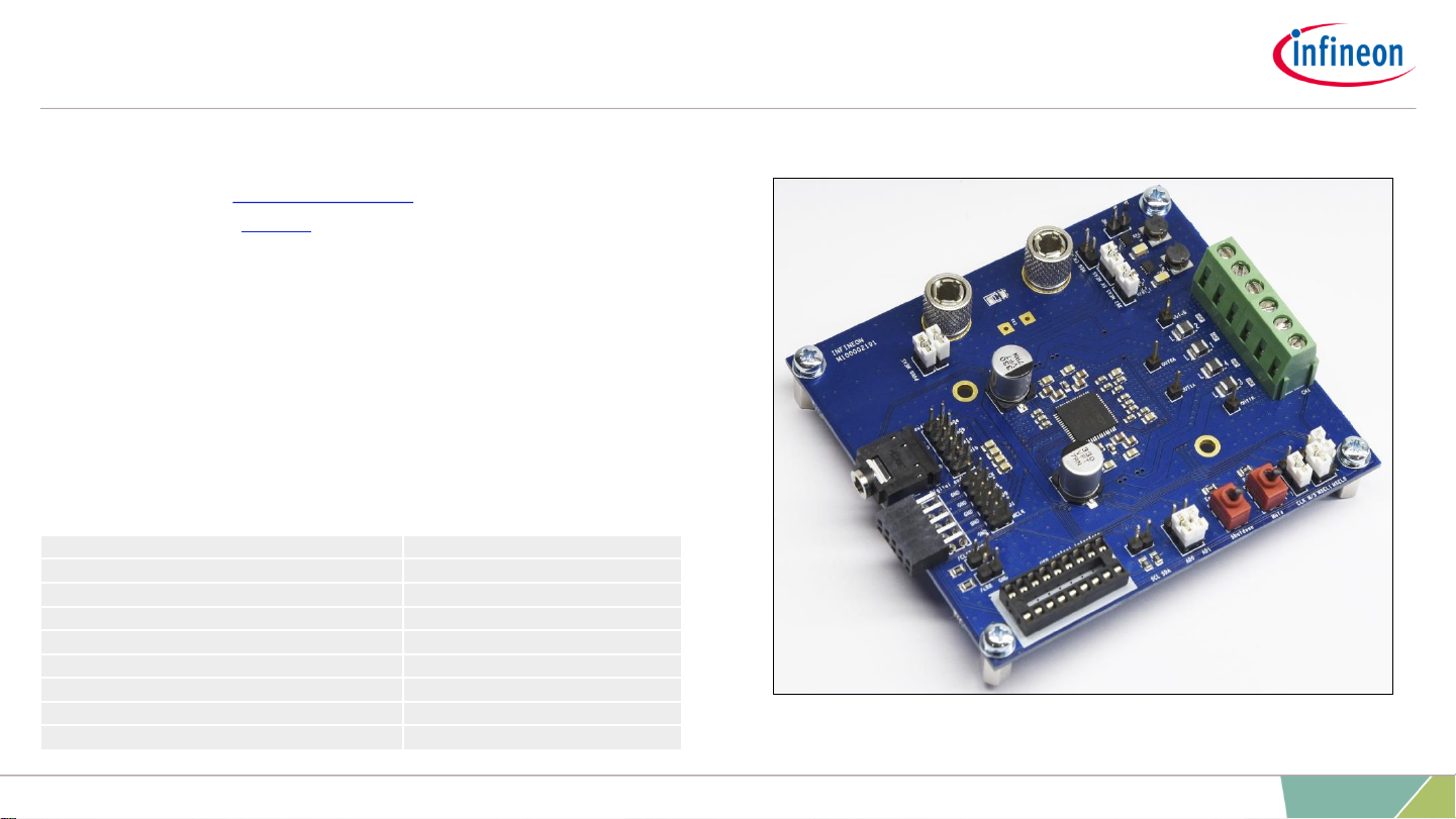
The demonstration board EVAL_AUDIO_MA12040 is an evaluation and demonstration
board for MERUS™ audio MA12040. It contains analog inputs and a variety of output
and setup/selection features. It also contains two on-board power supply generators (5 V
and 3.3 V buck-converted) so only one external power supply (PVDD) is necessary. The
board can be used for evaluating or demonstrating key features/advantages of the
MERUS™ technology:
> Energy efficiency: Power losses at typicalaudio listening levels / Idle power loss
> Adaptive power management system
> Minimum output filter components: Significant cost and size reduction.
> THD performance and audio quality
2
2019-04-25 Copyright © Infineon Technologies AG 2019. All rights reserved.
› General features and audio performance
Number of audio channels
2xBTL, 1
xPBTL, 1xBTL+2xSE
Audio input format
Analog
Amplifier gain
20
dB / configurable 26dB
Supply voltage
18
V
Output noise level
<
100 uVrms(AW)
Dynamic range
>
100 dB
Idle consumption @ PVDD=18V
<
16 mA
Crosstalk
<
-85 dB
Efficiency, full
-scale, 8 ohm
91
%
Figure 1. Overview of EVAL_AUDIO_MA12040 evaluation board
Board description
3
2019-04-25 Copyright © Infineon Technologies AG 2019. All rights reserved.
> Recommended operation conditions
Parameter Part Nr Minimum
Nominal
Maximum Unit
PVDD MA12040 5.5 18 V
Output peak current MA12040 6.0 A
AC Analog input level
IN0A, IN0B, IN1A, IN1B
MA12040 6.0 Vpk
Parameter Conditions Typ Unit
Output power p/channel (peak)
THD+N = 10%, RL =
4 Ω, f =
1 kHz
40 W
Output power p/channel (peak)
THD+N = 10%, RL =
8 Ω, f =
1 kHz
20 W
Total harmonic distortion + noise
1kHz, POUT =
1 W, RL = 4 Ω 0.008 %
Total harmonic distortion + noise
1kHz, POUT =
20 W, RL = 4 Ω 0.010 %
Efficiency*
POUT =
2×40 W, 4 Ω , PMP = 0 87 %
Efficiency*
POUT =
2×20 W, 8 Ω , PMP = 0 91 %
> Typical audio and electrical specifications
(BTL default configuration; Power Mode Profile = 0)
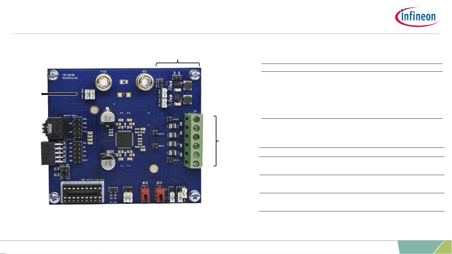
USB control
interface
Speaker
output
terminals
Power supply terminals
Device
enable/
mute
Output
configuration
jumpers
I2C
address
selection
3V3 / 5 V internal supply with
measurement and enable
jumpers
Power input
measurement
jumpers
Error and clipping
reading outputs
I2C
serial
clock
and data
Figure 2. Top board view of EVAL_AUDIO_MA12040
0B
GND
0A
1A
GND
1B
Analog
audio input
(non p versions)
I2S digital
audio input
(p versions only)
* Efficiency values do not take into account the 5 V and 3V3 board power supplies’ consumption.
Default configuration for a quick start
4
2019-04-25 Copyright © Infineon Technologies AG 2019. All rights reserved.
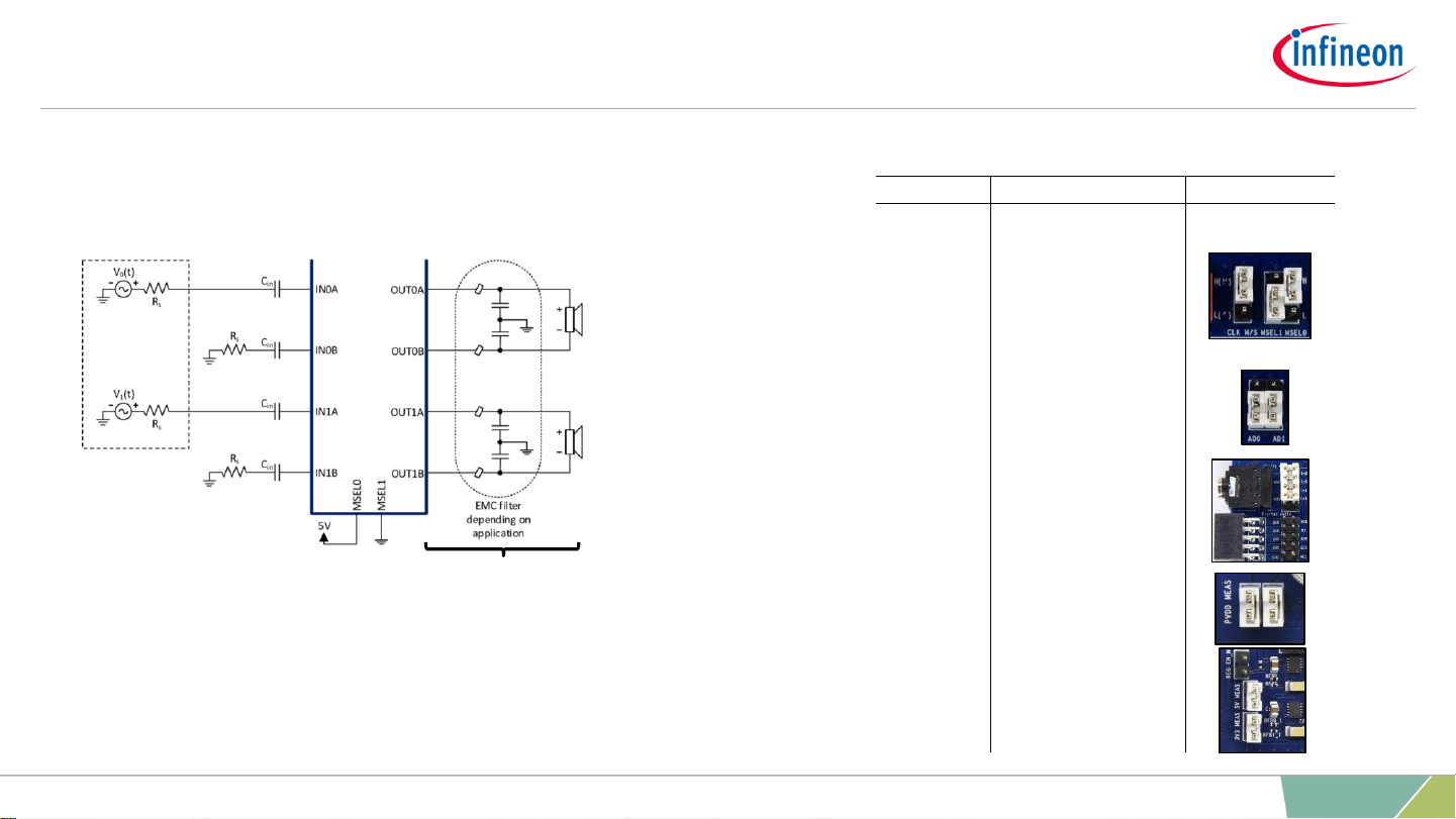
Bridge tied load (BTL)
outputs
Slides 4 and 5 describe the start up and quick start
operation procedures with the following configuration:
Single ended audio sources
Verify that the jumpers are set in the following positions:
Jumper State Picture
MSEL0
H
MSEL1
L
CLK M/S
H(M)
AD0 & AD1
L
Analog audio
Jack input = all jumpered
Balanced input = use individual
pints.
Digital audio
Do not Jumper
PVDD MEAS
Jumpered
3V3 & 5V
MEAS
Jumpered
REG EN_N
Do not Jumper
Figure 3. Bridge tied load (BTL) configuration with single ended inputs for MA12040
Note: Please refer to the manual for other Input/Output configurations. Typically
balanced/differential inputs should be used to obtain optimum audio performance.
 Loading...