

Page 1

AN-HPDKIT-GATEDRIVE
Manual for HybridKIT Evaluation Gate Board
HybridKIT Evaluation Gate Driver Board for 750V EDT2 IGBT
About this document
This application note describes the features as well as limitations of the evaluation gate driver board
EVAL-6ED100HPDRIVE-AS for HybridPACK™ Drive modules with 750V EDT2 IGBTs. A comprehensive
quickstart guide with main interfaces and function description is given. The evaluation gate driver board is
equal to the gate driver boards on the HYBRIDKIT DRIVE Inverter evaluation kits and is an open design for lab
testing purposes.
For evaluation of HybridPACK™ Drive modules with 1200V IGBT4 chipset please see [4].
Author: Tomas Reiter (IFAG ATV HP EDT MD).
Scope and purpose
The evaluation gate driver board was designed to support customers during their first steps in designing
applications with the HybridPACK™ Drive and EICEDriver Sense/Boost. An evaluation board is not intended to
be an optimal design for every specific requirement. But it gives a good starting point and useful design hints
for a serial development. Furthermore, practical experience from the power module switching characteristic as
well as the gate driver features can be obtained in the lab at a minimum effort by using such evaluation tools.
Before getting started it is mandatory to read and understand the safety warnings (section 1.1) and the features
and limitations (chapter 3).
Intended audience
Experienced engineers designing gate drive boards for HybridPACK™ Drive.
Table of Contents
1 Introduction .................................................................................................................. 2
1.1 Safety Warning for Evaluation Kit ........................................................................................................... 2
2 How to order Gate Driver Boards (EVAL-6ED100HPDrive-AS) .............................................. 3
3 Feature and Limitations Overview ................................................................................... 4
3.1 Block Diagram & Key Features ................................................................................................................ 4
3.2 Operating Mode “Inverter Kit” & “Stand Alone” .................................................................................... 4
3.3 Recommended Operating Conditions .................................................................................................... 5
3.4 Limitations of the Evaluation Kit ............................................................................................................ 5
3.5 Key Components List .............................................................................................................................. 6
4 Quickstart Guide ............................................................................................................ 7
4.1 Recommended equipment for evaluation ............................................................................................. 7
4.2 Interface and Testpad Description ......................................................................................................... 7
4.2.1 Signal Connector Pinnout & Interface PCB ....................................................................................... 7
4.2.2 Overview of Testpads ......................................................................................................................... 8
4.3 Supply of the Gate Driver Board ............................................................................................................. 9
4.4 Double Pulse Testing in driver DEBUG Mode (w/o SPI communication) ............................................ 10
4.4.1 Enabling DEBUG Mode ..................................................................................................................... 10
4.4.2 Switching the gate driver ................................................................................................................. 11
4.5 Using the gate driver boad with HybridKIT logic board....................................................................... 12
4.6 Digital NTC Measurement R2f converter (SPI required) ...................................................................... 12
5 References and Revision History .................................................................................... 13
Application Note Please read the Important Notice and Warnings at the end of this document <Revision 1.2>
www.infineon.com <2017-11-09>
Page 2

Manual for HybridKIT Evaluation Gate Board
HybridKIT Evaluation Gate Driver Board for 750V EDT2 IGBT
Introduction
1 Introduction
The evaluation gate driver board EVAL-6ED100HPDRIVE-AS is an isolated six channel gate driver board
dedicated for evaluation purpose of HybridPACK™ Drive products with 750V EDT2 IGBT chipset. It comes with
the new Infineon automotive EICEDriver Sense/Boost gate driver ICs. The evaluation gate driver board supports
the customers in their first steps designing applications with the HybridPACK™ Drive or the EICEDriver
Sense/Boost.
Please read and understand the manual and the following safety warnings (see section 1.1).
1.1 Safety Warning for Evaluation Kit
The design operates with unprotected high voltages. Therefore, the Evaluation Kit may only be handled by
persons with sufficient electrical engineering training and experience. The customer assumes all responsibility
and liability for its correct handling and/or use of the Evaluation Kit and undertakes to indemnify and hold
Infineon Technologies harmless from any third party claim in connection with or arising out of the use and/or
handling of the Evaluation Kit by the customer.
The Evaluation Kit is a sample to be used by the customer solely for the purpose of evaluation and testing. It is
not a commercialized product and shall not be used for series production. The Evaluation Kit is thus not
intended to meet any automotive qualifications. Due to the purpose of the system, it is not subjected to the
same procedures regarding Returned Material Analysis (RMA), Process Change Notification (PCN) and Product
Withdraw (PWD) as regular products. See Legal Disclaimer and Warnings for further restrictions on Infineon
Technologies warranty and liability.
European legislation in relation to inter alia the restriction of hazardous substances (RoHS), waste from
electrical and electronic equipment (WEEE), electromagnetic compatibility, as well as duties to comply with CE,
FCC or UL standards do not apply to the Evaluation Kit and the Evaluation Kit may not fulfill such requirements.
LEGAL DISCLAIMER
GUARNATEE OF CONDITIONS OR CHARACTERISTICS (“BESCHAFFENHEITSGARANTIE”). WITH RESPECT TO ANY
EXAMPLES OR HINTS GIVEN HEREIN, ANY TYPICAL VALUES STATED HEREIN AND/OR ANY INFORMATION REGARDING
THE APPLICATION OF THE EVALUATION KIT, INFINEON TECHNOLOGIES HEREBY DISCLAIMS ANY AND ALL
WARRANTIES AND LIABILITIES OF ANY KIND, INCLUDING WITHOUT LIMITATION WARRANATIES OF
NON_INFRINGEMENT OF INTELLECTUAL PROPERTY RIGHTS OF ANY THIRD PARTY.
Information For further information on technology, delivery terms and conditions and prices, please contact
the nearest Infineon Technologies Office (www.infineon.com).
Warnings Due to technical requirements, components may contain dangerous substances. For information on
the types in question, please contact the nearest Infineon Technologies Office. Infineon Technologies
components may be used in life-support devices or systems only with the express written approval of Infineon
Technologies, if a failure of such components can reasonably be expected to cause the failure of that lifesupport device or system or to affect the safety or effectiveness of that device or system. Life support devices or
systems are intended to be implanted in the human body or to support and/or maintain and sustain and/or
protect human life. If they fail, it is reasonable to assume that the health of the user or other persons may be
endangered.
THE INFORMATION GIVEN IN THIS DOCUMENT SHALL IN NO EVENT BE REGARDED AS A
Application Note 2 <Revision 1.2>
<2017-11-09>
Page 3
Manual for HybridKIT Evaluation Gate Board
HybridKIT Evaluation Gate Driver Board for 750V EDT2 IGBT
How to order Gate Driver Boards (EVAL-6ED100HPDrive-AS)
2 How to order Gate Driver Boards (EVAL-6ED100HPDrive-AS)
The evaluation gate driver board EVAL-6ED100HPDRIVE-AS, compatible for HybridPACK™ Drive 750V EDT2 IGBT
modules FSxxxR08A6P2xx, can be ordered via Infineon Sales Partners:
SAP ordering number for EVAL-6ED100HPDRIVE-AS: SP001386654.
The shipping content include:
Gate driver board compatible to FSxxxR08A6P2xx.
Interface PCB.
Please note that the gate driver board comes without logicboard, software, cooler, DC-link capacitor, etc. The
gate driver board is equal to the gate driver board of the full inverter evaluation kit HYBRIDKIT DRIVE and also
HYBRIDKIT DRIVE SENSE. See [2] for information how to order the full inverter evaluation kit. The typical
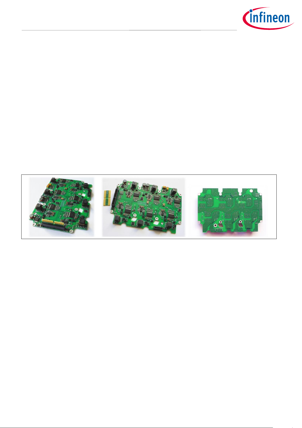
appearance of the stand alone gate driver board is shown in Figure 1, where also the small interface PCB can be
seen. This PCB provides a 1-1 connection to the 80pin signal connector and can be used e.g. with the logic
board from the HybridKITs.
Figure 1 Typical appearance of the gate driver evaluation board EVAL-6ED100HPDRIVE-AS (SP001386654)
from side, top and bottom view.
For gate driver boards compatible to HybridPACK™ Drive modules with 1200V IGBT4 chipset FSxxxR12A6T4xx
please see [4]
Application Note 3 <Revision 1.2>
<2017-11-09>
Page 4

Manual for HybridKIT Evaluation Gate Board
HybridKIT Evaluation Gate Driver Board for 750V EDT2 IGBT
Feature and Limitations Overview
3 Feature and Limitations Overview
3.1 Block Diagram & Key Features
The Figure 2 shows the block diagram with simplified signal and power flow.
Figure 2 Simplified block diagram. Right side show exemplarily the six EICEDrivers with the booster ICs as
companion parts.
The key features can be summarized:
6x isolated gate driver channels compatible for HybridPACK™ Drive power modules with EDT2 IGBT
chipset (FSxxxR08A6P2xx)
Gate driver solution based on EICEDriver Sense/Lite 1EDI2010AS/1EDI2015AS and EICEDriver BoostLite
1EBN1002AE. #
IGBT desaturation (short circuit) detection.
IGBT overvoltage protection via active collector gate clamping (<750Vces clamping).
All programmable functions from the EiceDRIVER Sense and Boost via SPI communication.
Digital NTC temperature measurement with R2f converter
featured by EiceDRIVER Sense/Lite 1EDI2010AS/1EDI2015AS (requires SPI communication).
Power supply with reverse polarity protection for 8..18V input voltage
featured by TLE8386-2EL
6x isolated power supply for +15V/-8V gate driver supply
Redundant digital DC-Link voltage measurement up to 550Vdc
featured by ADC of EICEDriver Sense 1EDI2010AS.
256kbyte EEPROM (requires SPI communication).
Single side SMD assembly for simple evaluation and measurements.
# The gate drivers 1EDI2010AS & 1EDI2015AS are pin and software compatible. The EICEDriver Sense
1EDI2010AS come with an additional ADC used in this design for measurement of the DC-link voltage. The
design uses features of the BoostLite 1EBN1002AE but it is fully compatible to the Boost 1EBN1001AE.
3.2 Operating Mode “Inverter Kit” & “Stand Alone”
The evaluation gate driver board was designed to be used in the HybridKIT Drive with SPI communication. In
the HybridKITs it comes with already preprogrammed settings which means the HybridKIT logic board detects
the version and loads the right software librarys for the EiceDrivers automatically. Before using a gate driver
board in a HybridKIT Drive the gate driver board has to be initialized as described in chapter 4.5.
The gate driver can be also used stand alone and also without SPI communication for e.g. simple double pulse
switching tests. For this purpose please follow the description of chapter 4.4.
Application Note 4 <Revision 1.2>
<2017-11-09>
Page 5

Manual for HybridKIT Evaluation Gate Board
HybridKIT Evaluation Gate Driver Board for 750V EDT2 IGBT
Feature and Limitations Overview
Type
Symb
Min
Max
Conditions
Gate Driver Board Supply
V
supply
8V
18V
Working Voltage
Capacitor DC-Link Voltage
VDC
0V
500V*
550V* short time
* limited by TVS clamping diodes
Ambient Temperature
T
amb
-40°C
85°C*
Limited by PCB temperature. Use
fan for testing >85°C.
Switching frequency
fsw 12 kHz
Thermal limited by T
PCB
Up tp 18kHz at low ambient
temperature or active cooling
3.3 Recommended Operating Conditions
The following recommended operating conditions describe the targeted lab testing environment.
Testing beyond the given area may be possible in specific cases when all individual parts are driven within their
specification. On the other hand the evaluation gate driver board together with the power module should not
be regarded as a protected system. It is not a considered product for end customers. The intention of the
evaluation gate driver board is to support engineers in their first steps designing with the Infineon EICEDrivers
and HybridPACKs. Please see also the section 3.4 in order to understand the limitations.
Table 1 Operating Conditions
The operating temperature is mainly limited by the power dissipation of the power supply implemented on the
evaluation kit board. The gate drivers, gate resistances are not the limitation in this design.
3.4 Limitations of the Evaluation Kit
The gate driver board with the power module should not be regarded as a protected system. It was designed
for evaluation under lab conditions with minimum automatic shutdown routines. The design was intended to
be usable also under extreme conditions where protection mechanism would limit the evaluation possibilities.
The evaluation gate driver board is not protected against:
Over- & undervoltages on the signal connectors.
Overvoltages of the HV working voltage
(>550V may damage the clamping diodes and/or lead to IGBT short circuit destruction)
Overtemperature of the PCB and module.
The power module NTC temperature info can be obtained as digital signal, but no shutdown limit is set
by the gate driver board.
Testing at high switching frequencies may require an active cooling of the gate driver board especially
at high ambient temperatures.
Please read and understand the manual and the safety warnings (see section 1.1).
Please note that the list are giving examples and should not be seen exhaustive.
Application Note 5 <Revision 1.2>
<2017-11-09>
Page 6

Manual for HybridKIT Evaluation Gate Board
HybridKIT Evaluation Gate Driver Board for 750V EDT2 IGBT
Feature and Limitations Overview
Part Number
Manufacturer
Description / Implementation
1EDI2010AS
(1EDI2015AS)
Infineon Technologies AG
Automotive Isolated Gate Driver EICEDriver Sense
(EICEDriver Lite)
1EBN1002AE
(1EBN1001AE)
Infineon Technologies AG
Automotive Booster Stage EICEDriver Boost
(EICEDriver Boost Lite)
TLE8386-2EL
Infineon Technologies AG
Automotive SMPS controller
used in 500kHz SEPIC converter
IPG20N06S2L-65
Infineon Technologies AG
Automotive Optimos
used in 500kHz SEPIC converter
BSL303SPE
Infineon Technologies AG
Automotive p-channel MOSFET
used for reverse polarity protection
TLE7274-2D
Infineon Technologies AG
Automotive LDO linear 5V regulator
used for driver input supply
IND784775122
Würth
Automotive Power Inductor (used in 500kHz Sepic)
P100403-A1
(B78307-A2276-A003)
TDK/Epcos
Automotive Transformer 1:1.1
for isolated bipolar gate drive supply
3.5 Key Components List
Some of the key components are not in the focus of the manual. Nevertheless besides the gate driver and
booster stage other active and passive components can be tested/evaluated under real application conditions.
Table 2 Key components list.
Application Note 6 <Revision 1.2>
<2017-11-09>
Page 7

Manual for HybridKIT Evaluation Gate Board
HybridKIT Evaluation Gate Driver Board for 750V EDT2 IGBT
Quickstart Guide
4 Quickstart Guide
This chapter explains briefly about the recommended lab equipment and how the gate drivers can be switched.
4.1 Recommended equipment for evaluation
In order to evaluate the gate driver board and HybridPACK™ Drive modules the following equipment is
mimimum recommended.
Power Supply: 8-18V, 2A
Signal pulse generator with 0V..5V output
4 channel scope
Optional SPI communication (up to 1MHz) for using programmable features of the EICEDriver
Load: HybridPACK™ Drive FSxxxR08A6P2xx.
See application note “assembly instructions” for correct PCB and power module assembly [1].
4.2 Interface and Testpad Description
4.2.1 Signal Connector Pinnout & Interface PCB
The evaluation gate driver board is equipped with a Samtec board to board connector. It is compatible to the
Infineon Aurix Microcontroller logic board, which is used for all HybridKits. The small interface PCB is designed
as 1:1 connector.
Figure 3 Board to board signal connector and pinout.
Application Note 7 <Revision 1.2>
<2017-11-09>
Page 8

Manual for HybridKIT Evaluation Gate Board
HybridKIT Evaluation Gate Driver Board for 750V EDT2 IGBT
Quickstart Guide
a)
b)
Area No
Description
1
Gate drive board supply voltage 8..18V (2A)
2
Pre-regulated 15V
3
Gate Driver Channel: Phase U lowside
4
Gate Driver Channel: Phase U highside
5
Gate Driver Channel: Phase V lowside
6
Gate Driver Channel: Phase V highside
7
Gate Driver Channel: Phase W lowside
8
Gate Driver Channel: Phase W highside
9
SPI communication
4.2.2 Overview of Testpads
The gate driver board is equipped with several SMD testpads. The signals are written on the PCB close to the
corresponding testpad. In order to get an overview of the available testpads see Figure 4 & Table 3.
Figure 4 The testpad areas indicated on the gate driver board (a). See Table 3 for description. Important
testpads are positioned also at side of the signal connector (b) (only revision “Sense_V1.2” and later).
Table 3 Testpad overview.
Application Note 8 <Revision 1.2>
<2017-11-09>
Page 9

Manual for HybridKIT Evaluation Gate Board
HybridKIT Evaluation Gate Driver Board for 750V EDT2 IGBT
Quickstart Guide
4.3 Supply of the Gate Driver Board
The gate driver board requires a low voltage supply between 8V..18V for the operation. For longer testing times
a voltage at about 14V is preferred.
Figure 5 The gate driver board can be supplied from the signal connector e.g. via the interface PCB
(reverse polarity protected) or alternative directly on the PCB testpads. Please respect the right supply
polarity when using the testpads!
The green LEDs (marked with 12V and 5V on the PCB top located of the connector) indicate right power supply
of the gate driver board.
Application Note 9 <Revision 1.2>
<2017-11-09>
Page 10

Manual for HybridKIT Evaluation Gate Board
HybridKIT Evaluation Gate Driver Board for 750V EDT2 IGBT
Quickstart Guide
4.4 Double Pulse Testing in driver DEBUG Mode (w/o SPI communication)
4.4.1 Enabling DEBUG Mode
The evaluation gate driver board is designed with the new automotive EICEDriver Sense/Boost ICs. These come
with a high number of programmable features (via SPI communication). For first evaluation tests, like double
pulse testing, a SPI communication is preferred but not mandatory. The IC has an option called “DEBUG MODE”
which can be enabled at power up and allows afterwards an operation similar to typical gate drivers with basic
functions.
Figure 6 Removing the 0R resistor bridge (marked on the PCB) at each gate driver channel enables the
DEBUG mode at next power up cycle. The gate driver is then ready to be used without SPI communication
in a basic configuration without advanced features.
Please note: The 0R resistor bridge and SPI communication is required when the board is used in the HybridKIT
inverter mode. Without SPI communication the logicboard will stop operation as NTC temperature reading and
ADC functions for DC-voltage measurement are not working.
Application Note 10 <Revision 1.2>
<2017-11-09>
Page 11

Manual for HybridKIT Evaluation Gate Board
HybridKIT Evaluation Gate Driver Board for 750V EDT2 IGBT
Quickstart Guide
4.4.2 Switching the gate driver
After the DEBUG mode is activated (section 4.4.1) the gate driver is ready to be switched without SPI
communication.
Before switching the gate driver, it has to be enabled:
Connect 5V_DIG with EN (see Figure 7).
nFLTA LED ON (close to signal connector) will indicate the driver ready signal.
Now the gate can be controlled by the PWM signal:
Connect 5V_DIG with PWM_xx OR connect a 5V signal generator between GND_DIG and PWM_xx and
perform pulses (see Figure 7).
Short Circuit (desaturation) or IGBT open detection:
A IGBT desaturation (DESAT) event is indicated to the operator by turning off the corresponding nFLTA
LED (close to the signal connector). The gate driver is than looked and prevented from performing
output pulses. It can be reactivated by the following sequence:
Disconnect 5V_DIG from EN. Disabling the gate driver resets all error states.
Connect 5V_DIG with EN. Enabling the gate driver again.
The nFLTA LED will indicate driver again a ready signal.
Figure 7 The testpads GND_DIG, 5V_DIG, PWM_xx, EN can be used to perform simple output pulses. The
testpads on the right picture simplify the access to the testpads (only revision “Sense_V1.2” and later).
Application Note 11 <Revision 1.2>
<2017-11-09>
Page 12

Manual for HybridKIT Evaluation Gate Board
HybridKIT Evaluation Gate Driver Board for 750V EDT2 IGBT
Quickstart Guide
4.5 Using the gate driver boad with HybridKIT logic board
The evaluation gate driver board is equal to the gate driver board used in the HYBRIDKIT DRIVE inverter
evaluation kits. For evaluation, benchmark, repair, etc. purpose it can be required to setup the boad for the use
with the HybridKIT logic boards. Please see [3] for information about USB/RS232 Terminal communication with
the logic board. After setup of the basic communication with the logic board an error message after the startup
may occur. The reason is that the EEPROM on the gate driver board as stand alone board is not programmed in
shipping state. Thus the logic board cannot identify the board and cannot select the right software functions
for the specific board version and revision.
After a power up with logic board, following commands can be typed in the USB/RS232 terminal program:
Shell>setup unlock
Shell>setup db version dbhpdsense {version} {rev}
for example the SENSE V1.2:
Now the console output the following:
Creating board version file system
Un-mounting existing file system...
Formating...
…
It is now recommended to ensure that standard parameter set is applied by typing the following command:
Shell>setup reset
Now the system can be restarted (power cycle board) and is ready to use.
setup db version dbhpdsense 1 2
4.6 Digital NTC Measurement R2f converter (SPI required)
The HybridPACK™ drive modules contain NTC resistors, which have specified resistance value as a function of
the temperature. The main challenge is to get this signal robust and with a good resolution to the uController.
Furtermore, as the NTC is very close to the high voltage switching IGBT and Diodes such a NTC should be
isolated because in case of severe system failures, arcing for example can cause high voltage potentials on the
NTC which has to be isolated from the uController for safety reasons. Digital signals are much easier to transfer
via galvanic isolated barriers compared to analog signals.
The gate driver board implements a digital NTC resitance reading with concept shown in Figure 8. The NTC
resistance value is converted in a 5V frequency modulated signal (R2f circuit). This digital frequency signal is
transferred via the DIO channel of the EICEDriver. The gate driver acts as a galvanic isolation barrier. On the low
voltage side, the uController can read this frequency signal (counting rising/falling egdes in defined time
periods) and calculates back to the temperature value of the NTC.
Figure 8 Concept of the implemented digital NTC measurement with resistance to frequency (R2f)
converter.
Application Note 12 <Revision 1.2>
<2017-11-09>
Page 13

Manual for HybridKIT Evaluation Gate Board
HybridKIT Evaluation Gate Driver Board for 750V EDT2 IGBT
References and Revision History
Revision History
Date
Version
Changed By
Change Description
2017-01
1.0
Tomas Reiter
(IFAG ATV HP EDT MD)
Initial Version
2017-03
1.1
T. Reiter
Minor updates. Picture update and revised wording.
2017-11
1.2
T. Reiter
Added reference to driver board variant for 1200V IGBT4 Module
Minor updates.
5 References and Revision History
The referenced application notes can be found at http://www.infineon.com
[1] Infineon Application Note AN-HPD-ASSEMBLY, “Assembly Instructions for the HybridPACK Drive”.
[2] Infineon Application Note AN-HPDKIT-QUICKSTART, “HybridKit Drive Quickstart Guide”.
[3] Infineon Application Note AN-HPDKIT-ADVANCED-FEATURES, “HybridKit Drive Advanced Features”.
[4] Infineon Application Note AN-HPDKIT1200V-GATEDRIVE, “HybridKit Evaluation Gate Driver Board for
1200V IGBT4”.
Application Note 13 <Revision 1.2>
<2017-11-09>
Page 14

Trademarks of Infineon Technologies AG
AURIX™, C166™, CanPAK™, CIPOS™, CoolGaN™, CoolMOS™, CoolSET™, CoolSiC™, CORECONTROL™, CROSSAVE™, DAVE™, DI-POL™, DrBlade™, EasyPIM™,
EconoBRIDGE™, EconoDUAL™, EconoPACK™, EconoPIM™, EiceDRIVER™, eupec™, FCOS™, HITFET™, HybridPACK™, Infineon™, ISOFACE™, IsoPACK™,
i-Wafer™, MIPAQ™, ModSTACK™, my-d™, NovalithIC™, OmniTune™, OPTIGA™, OptiMOS™, ORIGA™, POWERCODE™, PRIMARION™, PrimePACK™,
PrimeSTACK™, PROFET™, PRO-SIL™, RASIC™, REAL3™, ReverSave™, SatRIC™, SIEGET™, SIPMOS™, SmartLEWIS™, SOLID FLASH™, SPOC™, TEMPFET™,
thinQ!™, TRENCHSTOP™, TriCore™.
Trademarks updated August 2015
Other Trademarks
All referenced product or service names and trademarks are the property of their respective owners.
Edition <2017-11-09>
Published by
Infineon Technologies AG
81726 Munich, Germany
© 2017 Infineon Technologies AG.
All Rights Reserved.
Do you have a question about this
document?
Email: erratum@infineon.com
Document reference
AN-HPDKIT-GATEDRIVE
IMPORTANT NOTICE
The information contained in this application note
is given as a hint for the implementation of the
product only and shall in no event be regarded as a
description or warranty of a certain functionality,
condition or quality of the product. Before
implementation of the product, the recipient of this
application note must verify any function and other
technical information given herein in the real
application. Infineon Technologies hereby
disclaims any and all warranties and liabilities of
any kind (including without limitation warranties of
non-infringement of intellectual property rights of
any third party) with respect to any and all
information given in this application note.
The data contained in this document is exclusively
intended for technically trained staff. It is the
responsibility of customer’s technical departments
to evaluate the suitability of the product for the
intended application and the completeness of the
product information given in this document with
respect to such application.
For further information on the product, technology,
delivery terms and conditions and prices please
contact your nearest Infineon Technologies office
(www.infineon.com).
WARNINGS
Due to technical requirements products may
contain dangerous substances. For information on
the types in question please contact your nearest
Infineon Technologies office.
Except as otherwise explicitly approved by Infineon
Technologies in a written document signed by
authorized representatives of Infineon
Technologies, Infineon Technologies’ products may
not be used in any applications where a failure of
the product or any consequences of the use thereof
can reasonably be expected to result in personal
injury.
 Loading...