

Page 1

Driver SBC
Evaluation Board
Getting Started
Rev 1.0 2013-08-02
Automoti v e Power
Page 2

Driver SBC Evaluation Board
Revision History: Rev 1.0, 2013-08-02
Previous Version: none
Page Subjects (major changes since last revision)
Driver SBC Evaluation Board
Getting Started
Driver SBC Evaluation Board 2 Rev 0.2, 2011-11-14
Page 3

Driver SBC Evaluation Board
Getting Started
Table of Contents
Table of Contents
1 Abstract...............................................................................................................................................4
2 Introduction ........................................................................................................................................4
3 Hardware .............................................................................................................................................5
3.1 Box Contents........................................................................................................................................5
3.2 Application Board overview ..................................................................................................................6
3.2.1 Circuit Description and Layout .............................................................................................................6
3.3 Hardware Settings................................................................................................................................8
3.3.1 Power Settings .....................................................................................................................................8
3.3.2 Jumper Overview & Settings ................................................................................................................8
4 Software ..............................................................................................................................................9
4.1 Software Installation .............................................................................................................................9
4.2 Getting Started ...................................................................................................................................10
4.2.1 Infineon Driver SBC Evaluation Board GUI .......................................................................................11
4.2.2 ‘Driver SBC Functional Test’ tab ........................................................................................................12
4.2.3 ‘SPI Command’ tab ............................................................................................................................16
4.2.4 ‘SPI Program’ tab ...............................................................................................................................19
4.2.5 ‘Run SPI Program’ tab .......................................................................................................................22
5 Additional Information .....................................................................................................................24
Driver SBC Evaluation Board 3 Rev 0.2, 2011-11-14
Page 4

Driver SBC Evaluation Board
Getting Started
1 Abstract
Note: The following information is given as a hint for the implementation of the device only and shall not be
regarded as a description or warranty of a certain functionality, condition or quality of the device.
This Evaluation Board description is intended to provide an overview to the hardware and software operation of
the Driver SBC Evaluation Board. The Evaluation Board can work with the following devices:
TLE9264QX/-2QX
TLE9266QX/-2QX
TLE9268QX/-2QX
For simplification reasons, the document it will be referred to the Driver SBC Evaluation Board
2 Introduction
Driver SBC family is designed specifically for automotive applications such as Door, Seat Control, HVAC, Body
Controller. The devices include a LIN and/or CAN physical interface.
The Driver SBC Evaluation Board is intended to provide a simple, easy-to-use tool for getting familiar with the
device and for first application tests. The Evaluation Board contains a Driver SBC application board, which is
equipped with a 96-pin connector to interface to the Power Easy kit (microcontroller board).
The Power Easy Kit is a testing and development platform to be used with Infineon devices. This kit uses a
16-bit microcontroller of the XC2000 processor family based on the high-performance C166S V2 core. The
Power Easy Kit board is designed with a special 96-pin connector for board extension test capability, i.e. to
interface with an application board such as the Driver SBC.
The Driver SBC SPI communication is emulated by the Power Easy Kit which is controlled by a PC-Software
(also included in the demo-kit wih installation instructions).
Please note that the uC Power Easy Kit needs to be obtained separately.
Driver SBC Features:
Very low quiescent current consumption in Stop- and Sleep Mode
Periodic cyclic sense in Normal-, Stop- and Sleep Mode
Periodic cyclic wake in Normal- and Stop Mode
Low-Drop Voltage Regulator 5V, 250mA
Low-Drop Voltage Regulator 5V, 100mA, robust against short to VS
High-Speed CAN Transceiver ISO11898-2/5 with Partial Networking
LIN Transceiver LIN2.1, J2602
Two Low-Side Outputs for Relay Drive with active zener clamping
Two High-Side Output 2Ω typ., four High-Side Outputs 7Ω typ., e.g. for LED lighting, cyclic sensing, etc.
Four independent PWM generators and two On/Off Timers
Three universal High-Voltage Wake Inputs for voltage level monitoring with cyclic sense functionality
Alternate High-Voltage Measurement Function, e.g. for battery voltage sensing
One universal Low-Voltage Wake Input for voltage level monitoring with cyclic sense functionality
SYNC input for external cyclic sense control via micro controller
Reset Output and Fail Output
Over temperature and short circuit protection feature
Wide input voltage and temperature range
Green Product (RoHS compliant) & AEC Qualified
Driver SBC Evaluation Board 4 Rev 0.2, 2011-11-14
Page 5
Driver SBC Evaluation Board
96-pin
connector
Getting Started
3 Hardware
The Driver SBC Evaluation Board is designed to be compatible with the Easy Kit Microcontroller Evaluation
Board. The Easy Kit plugs into the Evaluation Board via a standard 96-pin connector and allows easy interface
to the microcontroller via USB for SPI, CAN, LIN communication etc.
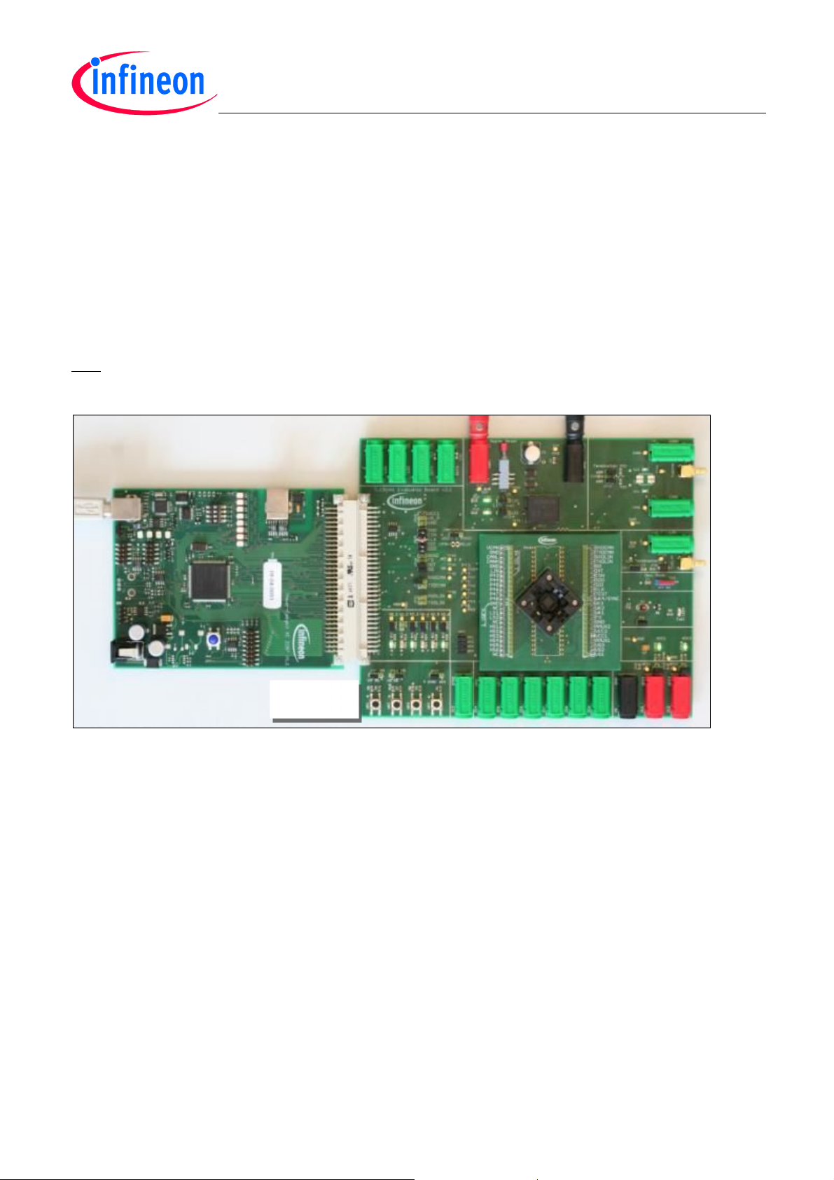
3.1 Box Contents
The following items are included in the Driver SBC Evaluation Board box:
Application Evaluation Board (Connection to the Power Easy Kit via 96-pin connector)
Note: The uC Power Easy Kit needs to be obtained separately
Figure 1 Power Easy Kit (left) connecting to the Driver SBC Evaluation Board (right)
Driver SBC Evaluation Board 5 Rev 0.2, 2011-11-14
Page 6
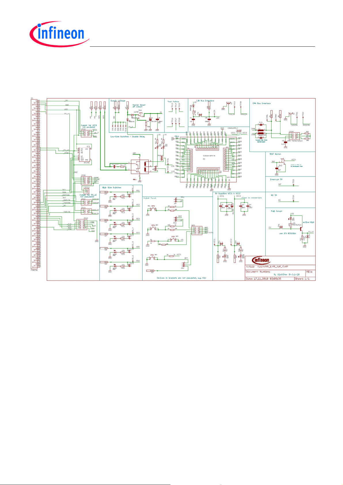
3.2 Application Board overview
3.2.1 Circuit Description and Layout
Driver SBC Evaluation Board
Getting Started
Figure 2 Driver SBC Evaluation Board Schematic
Driver SBC Evaluation Board 6 Rev 0.2, 2011-11-14
Page 7
Driver SBC Evaluation Board
Getting Started
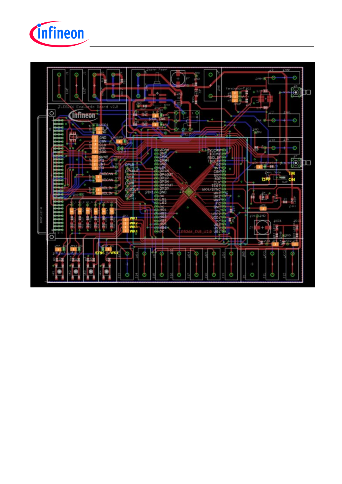
Figure 3 Driver SBC Evaluation Board Layout including default jumper settings.
The Evaluation board comprises of 2 layers, 35µm Cu. A small adapter board with a socket for a VQFN-48
package and a connector row on each side for easy measurement acces connects to the double connector row
(please note to connect in the right pinning order to avoid short circuits).
The PG-VQFN-48 package has an exposed pad and for good thermal performance. It is also possible to solder
the device directly on the PCB. Overall 9 thermal vias are placed directly below the exposed pad island. The
footprint is an absolute minial with no additional copper area. The most obvious heat flow is via the exposed pad
through the thermal vias.
Driver SBC Evaluation Board 7 Rev 0.2, 2011-11-14
Page 8

Driver SBC Evaluation Board
Getting Started
3.3 Hardware Settings
3.3.1 Power Settings
Connect VBATT and GND via standard power supply, with a nominal voltage of 13.5V. The Driver SBC is only
powered through this power supply.
3.3.2 Jumper Overview & Settings
For configuration purposes, there are several jumpers on the application board:
JP1 :
To be added in a table overview
Driver SBC Evaluation Board 8 Rev 0.2, 2011-11-14
Page 9

Driver SBC Evaluation Board
Getting Started
4 Software
4.1 Software Installation
The Power Easy Kit software delivered with the µC board must be installed first. Instruction details to the Power
Easy Kit software installation can be found in the Power easy Kit getting started V1_3.pdf document.
The latest ‘version file’ (Version 1.12 at the time this document was created) is required to be installed first. This
version is not compatible for the Driver SBC (another version will be released later). Therefore, additional standalone Power Easy Kit software needs to be installed by first uninstalling the existing Power Easy Kit version and
then installing the new version. This version is currently only available via our FAE team.
There is a version file called “version.txt”, which ensures that the correct GUI for the TLE9264/66/68 is selected.
The version file must be located in the same directory as the Power Easy Kit directory (\My
Documents\LabVIEW Data\power_easy_kit_data\version.txt).
In addition, the programmed firmware for the Power Easy Kit XC2287 microcontroller needs to have a revision
R15 or higher. If an existing uC-Power Easy Kit is used, it could be necessary to program the new .hex file to
the microcontroller (My Documents\LabVIEW Data\power_easy_kit_data\DemoEvalKitVX2.1R15.hex). Please
click the “Version Check” button in the main menu of the Power Easy Kit GUI to find out the programmed
version for the uC. Please use the “Update” button the main menu of the Power Easy Kit GUI to program a new
firmware on the microcontroller.
For older Power Easy Kit versions it could be necessary to modify the “version.txt” file for the latest GUI version.
Driver SBC Evaluation Board 9 Rev 0.2, 2011-11-14
Page 10

Driver SBC Evaluation Board
Getting Started
4.2 Getting Started
The Power Easy Kit software is executed by starting the ‘Power Easy Kit.exe’ in the installation directory or via
the Start Menu.
The following window will appear:
‘Start Demo’: A new window will open up to operate the Driver SBC. The device is automatically
indentified by the EEPROM located on the evaluation board and the respective GUI is started.
‘Stop’: The Power Easy Kit software will be closed. This is the safest way to end the program and is
recommended to avoid error messages or ‘bluescreens’.
‘Version check’: The actual firmware version of the microcontroller is displayed. Furthermore the
EEPROM of the evaluation board is read out.
‘Update’: The firmware of the microcontroller can be updated.
Notes:
Windows will resize all application fonts if your Windows font size is set to anything other than normal. This will
only affect compiled executables and not code running in the LabVIEW development environment.
Windows font size can be changed by navigating to Start Menu»Settings»Control Panel»Display»Appearance
Tab»Font Size (smaller 100%).
The window size of the GUI is fixed by LabView, i.e. it cannot be resized. To achieve a bigger font size the
screen resolution can be changed.
The “version.txt” file is in \MyDocuments\LabViewData\Power_easy_kit_data\version.txt
Driver SBC Evaluation Board 10 Rev 0.2, 2011-11-14
Page 11

After a click on ‘Start-Demo’ the following window will appear:
Driver SBC Evaluation Board
Getting Started
6
4.2.1 Infineon Driver SBC Evaluation Board GUI
The window above contains four tabs ‘Functional Test’, ‘SPI Command’, ‘SPI Programm’ and ‘Run SPI
Program’ to control and observe the Driver SBC.
The bar at the bottom of the window displays the connection status to the Driver SBC:
‘Communicating’
A light green flashing symbol indicates SPI data transmission between software and the Driver SBC.
‘Power EasyKit Comms OK’
If the symbol remains blue, the communication is working fine. Otherwise if the symbol is flashing
yellow, this indicates a communication problem between software and microcontroller. The safest way
to re-establish the connection is to close the software, reset the evalution and microcontroller board and
start the program again.
‘Update Rate’
The sliding controller allows configuring the update rate of the status register in the “Status Information”
field and the MS_CTRL register read out periodically. The period ranges from 64ms to 1.15s.
In the ‘File’ menu at the top the user can open and save his self-provided commands and programs (XML data
format). This functionalty will be described in detail later.
Driver SBC Evaluation Board 11 Rev 0.2, 2011-11-14
Page 12

Driver SBC Evaluation Board
Getting Started
4.2.2 ‘Functional Test’ tab
This tab informs the user about the chip status and allows controlling the most important Driver SBC settings.
In the upper left corner the section ‘Failure and Reset’ is located.
The button ‘SBC Soft Reset’ will send an SPI command to return all SPI
registers back to default and set the chip to “INIT MODE”.
The three symbols ‘INT’, ‘RO’ and ‘FO’ have a kind of “artificial glow” to
visualize the according signals to the user.
On the left side a section for SPI debugging can be found.
The 16 bit SPI words sent and received by the microcontroller can be
recorded by enabling the green checkbox on the left of ‘SPI Debug’.
In the listbox below the SPI data are displayed and the checkbox is flashing
light green and yellow to indicate data recording.
The recorded data are separated into transmitted and received SPI words,
each consisting out of a 4-bit hexadecimal number. At the top of the list the
last SPI sequence sent/received is displayed.
At the bottom of the section the SPI Clock frequency can be modified.
Note: In the GUI the SPI word is displayed with the MSB on the left. The
microcontroller in contrast is sending the SPI word inversely, starting with
the LSB!
Driver SBC Evaluation Board 12 Rev 0.2, 2011-11-14
Page 13

Driver SBC Evaluation Board
Getting Started
The framed sequence in the picture is taken as an example to illustrate the relevance of the individual Tx and
Rx bits:
Tx: 0046h= 0000 0000 0100 0110
Rx: 0411h= 0000 0100 0001 0001
b
b
Transmitted SPI word
Data Bits to the Driver SBC
R/
W
Address Bits
15 14 13 12 11 10 9 8 7 6 5 4 3 2 1 0
0 0 0 0 0 0 0 0 0 0 1 0 0 1 1 0
Bit 7 (Read/Write) is set to zero, i.e. the program is reading the register addressed by the
bits 6...0; In this case the address “0100110” belongs to the WK_STAT register.
Received SPI word
Data Bits from the Driver SBC Status Information
15 14 13 12 11 10 9 8 7 6 5 4 3 2 1 0
0 0 0 0 0 1 0 0 0 0 0 1 0 0 0 1
The data from the WK_STAT register are received in the bits 15...8. In the example the WK3_WU bit is
set. The bits 7...0 show if a bit is set in one of the according status register. [see data sheet 16.3]
Driver SBC Evaluation Board 13 Rev 0.2, 2011-11-14
Page 14

Driver SBC Evaluation Board
Getting Started
The section ‘Control Functions’ allows the user to change the main Driver SBC settings and is divided into
several sub-sections:
‘Mode and Supply Control’:
The SBC Mode can be changed by selecting
the respective entry in the ‘SBC Mode
Select’ dropdown menu, the actual mode is
displayed in the textbox below.
‘VCC1 Reset Threshold’ allows the user to
choose between four different values of
VCC1 undervoltage detection
‘VCC2 Configuration’ is used to
enable/disable VCC2 in the different modes.
‘Automatic Watchdog Trigger’:
It is possible to enable/disable the automatic
watchdog triggering and select between four
timer periods.
‘Bus Control’
The two dropdown menus ‘CAN
Configuration’ and ‘LIN Configuration’ are
used to configure the CAN- and LIN Bus
settings.
‘Wake Control’
The pins WK1/2/3 can be configured as wake capable by activating the respective checkbox.
If a pin is set to be wake capable, a voltage level change form low to high or high to low will cause a wake
event.
Each wake input can be connected to an internal pull-up/down resistor by selecting the respective entry from the
dropdown menu. Automatic means, that if a high level is detected the pull-up is activated, otherwise the pulldown resistore for a low level.
Furthermore the alternate measurement function with WK1 and WK2 can be enabled.
‘Switch Control’
The ‘Low-side Switches’ and ‘High-side Switches’ can be enabled/disabled manually by klicking the
corresponding HSx oder LSx checkbox.
Note: Once the watchdog triggering has been enabled in the “Functional Test” tab, it continues regardless of
which tab (‘Functional Test’, ‘SPI Command’, ‘SPI Program’ or ‘Run SPI Program’) is selected. The watchdog
trigger period can be changed in the other tabs but the automatic trigger function will overwrite this setting with
the next WD trigger.
Note: If the settings are modified in one of the other tabs (‘SPI Command’, ‘SPI Programm’ or ‘Run SPI
Program’) and you return back to the ‘Functional Test’ tab, the controls are not updated!
For example if the HS1 has been enabled in the SPI Command tab, the HS1 checkbox however will be grey. It
would be a high effort to read out the current state of all registers.
Driver SBC Evaluation Board 14 Rev 0.2, 2011-11-14
Page 15

Driver SBC Evaluation Board
Getting Started
The ‘Status Information’ section displays the bit mapping of the Driver SBC’s status register.
The software is only updating the status register automatically, when the ‘Functional Test’ tab is active.
A symbol is glowing light green, if the
respective bit in the status register is set.
Additional information of a bit is given when
the mouse pointer stays above the
corresponding symbol (hover tip):
Each status register can be cleared through
the button on the right.
All status registers are set to default by
pressing the ‘CLEAR ALL’ button in the
lower right corner.
Driver SBC Evaluation Board 15 Rev 0.2, 2011-11-14
Page 16

Driver SBC Evaluation Board
Getting Started
4.2.3 ‘SPI Command’ tab
This tab allows the definition of SPI commands. A command consists of one or more SPI words which can be
defined bit by bit and it can also contain a defined delay
When switching to ‘SPI Command’ for the first time after the program starts the tab will look like the following:
At the beginning almost every control device is greyed out and the ‘Build Command’ list is empty.
To edit/open a pre-saved command select the corresponding XML file via ‘File’ -> ‘Open’:
‘…TLE9266\Software\TLE9266 programs.xml’
To simply start with defining a new command press the ‘New’ button above
After opening the xml file or defining a new command, the tab will look like the following and every control
device is now accessible:
Driver SBC Evaluation Board 16 Rev 0.2, 2011-11-14
Page 17

Driver SBC Evaluation Board
Getting Started
At the top of the ‘SPI Command’ tab is a bar to manage the SPI commands:
In the middle is a dropdown symbol which enlists the commands from the XML file. The actual command is
displayed in the textbox on the left.
On the right are four buttons to edit the SPI commands in the xml file:
‘Edit Name’: A popup window will appear where the user is able to change the name of the actual
command
‘New’: A blank SPI command will be created and a popup window will appear to enter the name.
‘Duplicate’: The actual command is copied and inserted into the list as ‘…(copy)’
‘Delete’: The actual command is removed from the list
Note: New or changed commands are not automatically saved to the xml file! Always save your list to the XML
file via ‘File’ -> ‘Save’.
The sub-section ‘SPI Word Definition’ is divided into two sub-tabs, ‘SPI Write Register’ and ‘Delay’
Driver SBC Evaluation Board 17 Rev 0.2, 2011-11-14
Page 18

Driver SBC Evaluation Board
Getting Started
‘SPI Write Register’ is used to define a SPI word.
The name of the actual SPI word is displayed in
the ‘Word Name’ textbox and can be edited
there.
Below, the 16 bits of the word sent to the Driver
SBC can be arranged; their relevance is equal to
4.2.2 SPI Debug.
The address bits 0...6 are configured by selecting
an entry from the ‘Address Selection’ dropdown
list. By doing so the respective register is read
from the Driver SBC and the result is returned in
the ‘Data Back’ row to display the actual bit
mapping.
A hover tip on the address displays additional
information about the register function.
The bit 7 (Access Mode) can be selected write/read for control register and read/clear for status register.
The remaining bits 8…15 are the data bits and can be set to one/zero by enabling/disabling the
respective checkbox. Their function is displayed in the white textbox above.
The four buttons at the bottom have the following functionality:
‘Clear’: All bits in ‘Cmd Sent’ and ‘Data Back’ and the ‘Word Name’ are cleared
‘Test’: The actual configuration is directly sent to the Driver SBC
‘Insert’: The actual configuration is inserted into the neighboring ‘Build Command’ list on the right.
‘Update’: The actual configuration overwrites the word selected in the ‘Build Command’ list
In the ‘Delay’ tab a specific delay time can be
defined.
The time is configured by adjusting the slider or
directly writing the value into the white textbox.
‘Insert Delay’:
Adds the selected value to the ‘Build
Command’ list on the right.
‘Update Delay’: Modifies the delay value
selected in the ‘Build Command’ list
The sub-section ‘Command Definition’ is used to arrange the individual words of the SPI command that is
selected in the textbox ‘Command Name’. The list can contain up to 20 entries.
Driver SBC Evaluation Board 18 Rev 0.2, 2011-11-14
Page 19

Driver SBC Evaluation Board
Getting Started
‘Move Up/Down’: Changes the order of
the SPI words in the list
‘Delete’: Removes an entry from the list
‘Clear All’: Cleares the whole list
‘Single Step’: The SPI word marked blue
is executed an the cursor jumps to the
next entry. This allows sequential testing
of the words in the list.
‘Test’: Executes the whole list in the given
order.1At the end a window pops up
showing a summary of the transmitted
and received data, which can be stored in
a text file. [Figure 1]
‘View Output’: Opens a window showing
the transmitted data. [Figure 2]
‘Undo’: Revokes the last change made.
In this example the build command is a “running light” through the high side LED’s on the evaluation board.
Note: If there is an empty command or a command which only contains a delay, this will result in an error. In
each command the use of SPI is necessary; otherwise the program is stuck when executing the SPI program.
Figure 1
Figure 2
4.2.4 ‘SPI Program’ tab
1
In the actual software version the Fail Output may be triggered by mistake.An internal software error triggers chip select,
without sending data. The Driver SBC interprets this as SPI Stuck and activates the Fail Output.
Just clear the ‘Device Status’ register in the Driver SBC Functional Tab and continue working.
Driver SBC Evaluation Board 19 Rev 0.2, 2011-11-14
Page 20

Driver SBC Evaluation Board
Getting Started
The ‘SPI Program’ tab allows creating and modifying SPI programs. An SPI program is a list of SPI commands
which are executed sequentially.
The structure of the ‘SPI Program’ tab is very similar to the the ‘SPI Command’ tab described in the chapter
before.
Opening the tab for the first time after program start, most control devices are greyed out until a new program is
created or a pre-saved program is loaded from the XML file. It is the same file the SPI commands are stored in.
At the top of the ‘SPI Program’ tab is a bar to manage the available SPI programs:
In the middle is a dropdown symbol which enlists the programs from the XML file. The actual program is
displayed in the textbox on the left.
On the right are four buttons to edit the SPI programs in the xml file:
‘Edit Name’: A popup window will appear where the user is able to change the name of the actual
program
‘New’: A blank SPI program will be created and a popup window will appear to enter the name.
‘Duplicate’: The actual program is copied and inserted into the list as “….(copy)”
‘Delete’: The actual program is removed from the list
Note: New or changed programs are not automatically saved to the xml file! Always save your list to the XML
file via ‘File’ -> ‘Save’.
Driver SBC Evaluation Board 20 Rev 0.2, 2011-11-14
Page 21

Driver SBC Evaluation Board
Getting Started
The sub-section ‘SPI Commands Available’ displays the configured SPI commands from the list.
‘Insert’: The selected command is inserted into the neighboring ‘Build Programm’ list on the right.
‘Update’: The selected command overwrites the command selected in the ‘Build Program’ list
The sub-section ‘Program Definition’ allows arranging the commands of the actual SPI program.
‘Move Up/Down’: Changes the order of the SPI commands in the list
‘Delete’: Removes an entry from the list
‘Clear All’: Cleares the whole list
‘Test’: Executes the whole list in the given order.1The active command is highlighted by a yellow
background. At the ending a window pops up showing a summary of the transmitted and received data,
which can be stored in a text file. [Figure 1 on page 19]
‘View Output’: Opens a window showing the transmitted data. [Figure 2 on page 19]
‘Undo’: Revokes the last change made.
1
In the actual software version the Fail Output may be triggered by mistake.An internal software error triggers chip select,
without sending data. The Driver SBC interprets this as SPI Stuck and activates the Fail Output.
Just clear the ‘Device Status’ register in the Driver SBC Functional Tab and continue working.
Driver SBC Evaluation Board 21 Rev 0.2, 2011-11-14
Page 22

Driver SBC Evaluation Board
Getting Started
‘Run SPI Program’ tab
The ‘Run SPI Program’ tab allows multiple programs to be run sequentially or a single program to be run in
loops. This window is suitable for regression testing under various application conditions:
The ‘Programs Available’ section displays the SPI programs stored in the xml file. If the respective entry is
checked by a mouseclick, the program is added to the ‘Decoded SPI Program’ list.
The order of the programs can be modified by using the two arrows on the left.
The ‘Decoded SPI Program’ section itemizes the selected programs down to the lowest level and displays the
pre-configured SPI words.
Driver SBC Evaluation Board 22 Rev 0.2, 2011-11-14
Page 23

Driver SBC Evaluation Board
Getting Started
At the bottom are further control elements:
The loop button on the left allows running the ‘Decoded SPI Program’ several times.
‘Execute’: Starts to execute the ‘Decoded SPI Program’list.1A small window opens up showing the
current number of iterations.
Via the ‘STOP’ button the excecution of the sequence can be interrupted.
The active part of the program is highlighted by a yellow background in the Program Available section.
[Figure 3]
After the execution of the program was successful, a window pops up showing a summary of the
transmitted and received data. Again these data can can be stored in a text file. [Figure 4]
‘Save’: The ‘Decoded SPI Program’ can be stored to a text file for documentation only. It is not
possible to use the text file like the xml file as a template.
Figure 3
Figure 4
1
In the actual software version the Fail Output may be triggered by mistake.An internal software error triggers chip select,
without sending data. The Driver SBC interprets this as SPI Stuck and activates the Fail Output.
Just clear the ‘Device Status’ register in the Driver SBC Functional Tab and continue working.
Driver SBC Evaluation Board 23 Rev 0.2, 2011-11-14
Page 24

Driver SBC Evaluation Board
Getting Started
5 Additional Information
For further information you may contact http://www.infineon.com/SBC or your regional FAE.
Driver SBC Evaluation Board 24 Rev 0.2, 2011-11-14
Page 25

Edition 2011-11-14
Published by
Infineon Technologies AG
81726 Munich, Germany
© 2013 Infineon Technologies AG
All Rights Reserved.
LEGAL DISCLAIMER
THE INFORMATION GIVEN IN THIS APPLICATION NOTE IS GIVEN AS A HINT FOR THE
IMPLEMENTATION OF THE INFINEON TECHNOLOGIES COMPONENT ONLY AND SHALL NOT BE
REGARDED AS ANY DESCRIPTION OR WARRANTY OF A CERTAIN FUNCTIONALITY, CONDITION OR
QUALITY OF THE INFINEON TECHNOLOGIES COMPONENT. THE RECIPIENT OF THIS APPLICATION
NOTE MUST VERIFY ANY FUNCTION DESCRIBED HEREIN IN THE REAL APPLICATION. INFINEON
TECHNOLOGIES HEREBY DISCLAIMS ANY AND ALL WARRANTIES AND LIABILITIES OF ANY KIND
(INCLUDING WITHOUT LIMITATION WARRANTIES OF NON-INFRINGEMENT OF INTELLECTUAL
PROPERTY RIGHTS OF ANY THIRD PARTY) WITH RESPECT TO ANY AND ALL INFORMATION GIVEN IN
THIS APPLICATION NOTE.
Information
For further information on technology, delivery terms and conditions and prices, please contact the nearest
Infineon Technologies Office (www.infineon.com).
Warnings
Due to technical requirements, components may contain dangerous substances. For information on the types in
question, please contact the nearest Infineon Technologies Office.
Infineon Technologies components may be used in life-support devices or systems only with the express written
approval of Infineon Technologies, if a failure of such components can reasonably be expected to cause the
failure of that life-support device or system or to affect the safety or effectiveness of that device or system. Life
support devices or systems are intended to be implanted in the human body or to support and/or maintain and
sustain and/or protect human life. If they fail, it is reasonable to assume that the health of the user or other
persons may be endangered.
Page 26

w w w . i n f i n e o n . c o m
Published by Infineon Technologies AG
 Loading...