

Technische Information / Technical Information
Elektrische Eigenschaften / Electrical properties
Dioden-Modul mit Chopper-IGBT
Diode Module with Chopper-IGBT
DD B6U 104 N 16 RR N B6
Höchstzulässige Werte / Maximum rated values
Gleichrichterdiode / Rectifierdiode
Periodische Spitzensperrspannung
Tvj = - 40°C...T
vj max V
repetitive peak reverse voltage
Durchlaßstrom-Grenzeffektivwert (pro Element) I
RMS forward current (per chip)
Ausgangsstrom
TC = 100°C
output current
Stoßstrom-Grenzwert T
surge forward current
Grenzlastintegral T
I²t-value
= 25°C, tp = 10ms I
vj
Tvj = T
Tvj = T
, tp = 10ms
vj max
= 25°C, tp = 10ms I²t 2100 A²s
vj
, tp = 10ms
vj max
IGBT
Kollektor-Emitter-Sperrspannung V
collector-emitter voltage
Kollektor-Dauergleichstrom
TC = 80°C
DC-collector current
Periodischer Kollektor-Spitzenstrom
tp = 1ms
repetitive peak collektor current
Gesamt-Verlustleistung
TC = 25°C
total power dissipation
Gate-Emitter Spitzenspannung V
gate-emitter peak voltage
Schnelle Diode / Fast diode
Periodische Spitzensperrspannung V
repetitive peak reverse voltage
Dauergleichstrom
TC = 80°C
DC forward current
Periodischer Spitzenstrom
tp = 1ms
repetitive peak forward current
Modul
Isolations-Prüfspannung
insulation test voltage
RMS, f = 50Hz, t = 1min
NTC connected to baseplate
RRM
FRMSM
I
d
FSM
CES
I
C
I
CRM
P
tot
GE
RRM
I
F
I
FRM
V
ISOL
1600 V
60 A
105 A
650 A
550 A
1500 A²s
1200 V
50 A
100 A
350 W
± 20 V
1200 V
25 A
50 A
2,5 kV
Charakteristische Werte / Characteristic values
Gleichrichterdiode / Rectifierdiode min. typ. max.
Durchlaßspannung
forward voltage
Schleusenspannung
threshold voltage
Ersatzwiderstand
forward slope resistance
Sperrstrom
reverse current
Modul Leitungswiderstand, Anschlüsse-Chip
lead resistance, terminals-chip
prepared by: Ralf Jörke date of publication: 13.12.2000
approved by: Lothar Kleber revision: 1
BIP AM; R. Jörke 14. Dez 00 A 33/00 Seite/page 1(12)
Tvj = T
Tvj = T
Tvj = T
Tvj = T
TC = 25°C
, iF = 100A
vj max
vj max V
vj max r
V
vj max, vR =
RRM i
v
F
(TO)
T
R
R
AA`+KK`
1,30 V
0,75 V
5,5 mΩ
5 mA
1 mΩ
Technische Information / Technical Information
Elektrische Eigenschaften / Electrical properties
Thermische Eigenschaften / Thermal properties
Dioden-Modul mit Chopper-IGBT
Diode Module with Chopper-IGBT
DD B6U 104 N 16 RR N B6
Charakteristische Werte / Characteristic values
IGBT min. typ. max.
Kollektor-Emitter Sättigungsspannung
collector-emitter saturation voltage
Gate-Emitter-Schwellspannung
Tvj = 25°C, iC = 50A, vGE = 15V
Tvj = 125°C, iC = 50A, vGE = 15V
Tvj = 25°C, iC = 2mA, vGE = v
CE v
v
CE sat
GE(TO)
2,10 2,80 V
2,5
4,5 5,5 6,5 V
gate-emitter threshold voltage
Eingangskapazität
input capacitance
Kollektor-Emitter Reststrom
collector-emitter cut-off current
Gate-Emitter Reststrom
Tvj = 25°C, f0 = 1MHz,
vCE = 25V, vGE = 0V
Tvj = 25°C, vCE = 1200V, vGE = 0V
Tvj = 125°C, vCE = 1200V, vGE = 0V
Tvj = 25°C, vCE = 0V, vGE = 20V
C
i
CES
i
GES
ies
3,3 nF
0,8 1 mA
4,0
gate leakage current
Emitter-Gate Reststrom
Tvj = 25°C, vCE = 0V, vEG = 20V
i
EGS
gate-leakage current
Schnelle Diode / Fast diode
Durchlaßspannung
forward voltage
Sperrverzögerungsladung
recovered charge
Tvj = 25°C, iF = 25A
Tvj = 125°C, iF = 25A
iFM = 25A, -di/dt = 800A/µs, vR = 600V
Tvj = 25°C
Tvj = 125°C
v
F
1,7 2,20 V
1,6
Q
r
2,3 µAs
6,0 µAs
500 nA
500 nA
Innerer Wärmewiderstand
Übergangs-Wärmewiderstand
thermal resistance, case to heatsink
Gleichrichter / Rectifier, Θ = 120°rect
Transistor / Transistor, DC
Schnelle Diode / Fast diode, DC
Gleichrichter / Rectifier
Transistor / Transistor
Schnelle Diode / Fast diode
Höchstzulässige Sperrschichttemperatur T
max. junction temperature
Betriebstemperatur T
operating temperature
Lagertemperatur T
storage temperature
R
R
thJC
thCK
vj max
c op
stg
max. 1,08 °C/W
max. 0,38 °C/W
max. 1,00 °C/W
max. 0,25 °C/W
max. 0,24 °C/W
max. 0,30 °C/W
150 °C
- 40...+150 °C
- 40...+150 °C
BIP AM; R. Jörke 14. Dez 00 Seite/page 2(12)
Technische Information / Technical Information
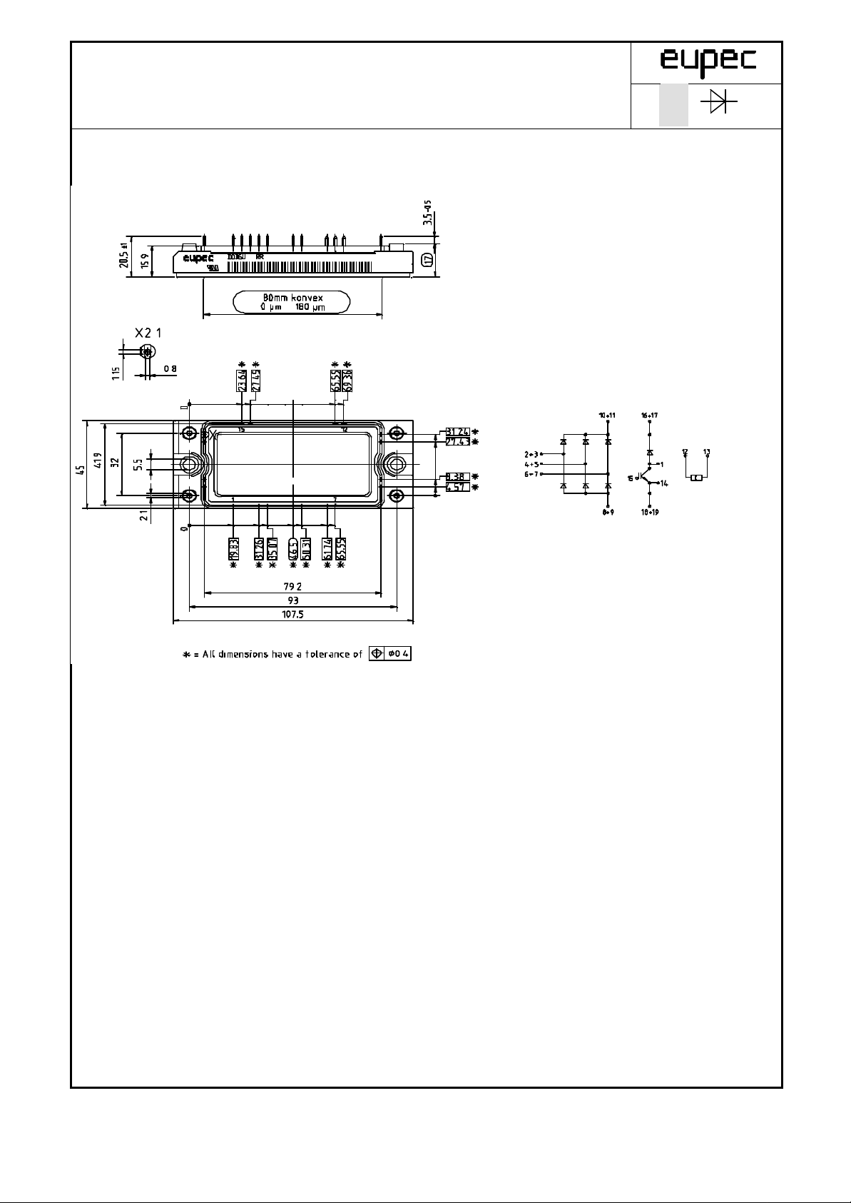
Mechanische Eigenschaften / Mechanical properties
Temperatursensor / Temperature sensor
Dioden-Modul mit Chopper-IGBT
Diode Module with Chopper-IGBT
DD B6U 104 N 16 RR N B6
Gehäuse, siehe Anlage Seite 4
case, see appendix page 4
Innere Isolation Al2O
3
internal insulation
CTI 225 V
comperative tracking index
Anzugsdrehmoment für mechanische Befestigung
Toleranz / tolerance ±15%
M1 4 Nm
mounting torque
Gewicht G typ. 185 g
weight
Kriechstrecke 12,5 mm
creepage distance
Schwingfestigkeit
f = 50Hz
50 m/s²
vibration resistance
Nennwiderstand
rated resistance
Verlustleistung
power dissipation
B-Wert
B-value
TC = 25°C
R
= 493Ω ± 5%
100
TC = 25°C
R2 = R1 exp [B(1/T1 - 1/T2)]
R
P
B
25
25
25/50
5 kΩ
max. 20 mW
3375 K
Mit dieser technischen Information werden Halbleiterbauelemente spezifiziert, jedoch keine Eigenschaften zugesichert. Sie gilt in Verbindung
mit den zugehörigen Technischen Erläuterungen. / This technical Information specifies semiconductor devices but promises no characteristics.
It is valid in combination with the belonging technical notes.
BIP AM; R. Jörke 14. Dez 00 Seite/page 3(12)
Technische Information / Technical Information
Dioden-Modul mit Chopper-IGBT
Diode Module with Chopper-IGBT
DD B6U 104 N 16 RR N B6
BIP AM; R. Jörke
14. Dez 00
Seite/page 4(12)

Technische Information / Technical Information
Dioden-Modul mit Chopper-IGBT
[
]
thn
[
]
Diode Module with Chopper-IGBT
Analytische Elemente des transienten Wärmewiderstandes Z
Analytical elements of transient thermal impedance Z
Pos. n 1 2 3 4 5 6 7
R C W
° /
τns
0,4063 0,3034 0,0497 0,0309
0,0300 0,0190 0,0140 0,0003
DD B6U 104 N 16 RR N B6
für DC, Netz-Diode
thJC
for DC, rectifier diode
thJC
n
max
∑
n
t
−
−=
1:
thnthJC
=
1
τ
n
eRZFunktioneAnalytisch
14. Dez 00 Seite/page 5(12)

Technische Information / Technical Information
Grenzdurchlaßkennlinie / Limiting on-state characteristic i
F
= f(vF)
Dioden-Modul mit Chopper-IGBT
Diode Module with Chopper-IGBT
200
180
160
140
DD B6U 104 N 16 RR N B6
Tvj = 150°C
[A]
F
i
120
100
80
60
40
20
0
0 0,2 0,4 0,6 0,8 1 1,2 1,4 1,6 1,8 2
BIP AM; R. Jörke
14. Dez 00
vF [V]
Seite/page 6(12)

Technische Information / Technical Information
Höchstzulässige Gehäusetemperatur / Maximum allowable case temperatur T
C
= f(Id)
Parameter: Stromrichterschaltung / converter circuit
Dioden-Modul mit Chopper-IGBT
Diode Module with Chopper-IGBT
150
140
130
120
110
DD B6U 104 N 16 RR N B6
100
[°C]
C
T
90
80
70
60
50
40
30
B2: 180°
sin
B6: 120°
rect
20
0 10 20 30 40 50 60 70 80 90 100 110 120
BIP AM; R. Jörke
14. Dez 00
Id [A]
Seite/page 7(12)

Technische Information / Technical Information
Sperrverzögerungsladung / Recovered charge Q
r
= f(-di/dt)
vjmax
RRM
RRM
Parameter: Durchlaßstrom / On-state current i
FM
Dioden-Modul mit Chopper-IGBT
Diode Module with Chopper-IGBT
1000
DD B6U 104 N 16 RR N B6
200A
50A
20A
100
[µAs]
r
Q
5A
10
1 10 100
- di/dt [A/µs]
Tvj = T
BIP AM; R. Jörke
; vR = 0,5V
; vRM = 0,8V
14. Dez 00
Seite/page 8(12)

Technische Information / Technical Information
Transienter innerer Wärmewiderstand Gleichrichter / Transient thermal impedance converter Z
thJC
= f(t)
Parameter: Stromflußwinkel / Current conduction angle
Dioden-Modul mit Chopper-IGBT
Diode Module with Chopper-IGBT
1,40
1,20
1,00
DD B6U 104 N 16 RR N B6
60° rect
120° rect
180° rect
180° sin
0,80
[°C/W]
thJC
Z
0,60
0,40
0,20
0,00
0,001 0,01 0,1 1
t [s]
DC
Θ
BIP AM; R. Jörke
14. Dez 00
Seite/page 9(12)

Technische Information / Technical Information
Ausgangskennlinienfeld Brems-Chopper-IGBT (typisch) / Output characteristic brake-chopper-IGBT (typical)
iC = f(vCE), v
GE
= 15V
Dioden-Modul mit Chopper-IGBT
Diode Module with Chopper-IGBT
100
90
80
70
DD B6U 104 N 16 RR N B6
Tvj = 25°C Tvj = 125°C
[A]
C
i
60
50
40
30
20
10
0
0 0,5 1 1,5 2 2,5 3 3,5 4
vCE [V]
BIP AM; R. Jörke
14. Dez 00
Seite/page 10(12)

Technische Information / Technical Information
Durchlaßkennlinie der Brems-Chopper-Diode (typisch) / On-state characteristic of brake-chopper-FWD (typical)
Dioden-Modul mit Chopper-IGBT
Diode Module with Chopper-IGBT
50
40
DD B6U 104 N 16 RR N B6
[A]
F
i
30
20
10
Tvj = 25°CTvj = 125°C
0
0 0,5 1 1,5 2 2,5
vF [V]
iF = f(vF)
BIP AM; R. Jörke
14. Dez 00
Seite/page 11(12)

Technische Information / Technical Information
NTC-Temperaturkennlinie (typisch) / NTC-temperature characteristic (typical) R = f(T)
Dioden-Modul mit Chopper-IGBT
Diode Module with Chopper-IGBT
100
10
DD B6U 104 N 16 RR N B6
]
Ω
R [k
1
0,1
0 10 20 30 40 50 60 70 80 90 100 110 120 130 140 150
T [°C]
BIP AM; R. Jörke
14. Dez 00
Seite/page 12(12)

Terms & Conditions of Usage
Attention
The present product data is exclusively subscribed to technically experienced
staff. This Data Sheet is describing the specification of the products for which a
warranty is granted exclusively pursuant the terms and conditions of the supply
agreement. There will be no guarantee of any kind for the product and its
specifications. Changes to the Data Sheet are reserved.
You and your technical departments will have to evaluate the suitability of the
product for the intended application and the completeness of the product data
with respect to such application. Should you require product information in
excess of the data given in the Data Sheet, please contact your local Sales Office
via “www.eupec.com / sales & contact”.
Warning
Due to technical requirements the products may contain dangerous substances.
For information on the types in question please contact your local Sales Office via
“www.eupec.com / sales & contact”.
 Loading...