

Page 1

Automotive Power
Getting Started
Rev 1.0, Dec 2018
TLE9273QX Evaluation Board
DCDC SBC Family
Page 2
TLE9273QX Evaluation Board
Getting Started
TLE9273QXEvaluation Board 2 Rev 1.0, Dec 2018
Revision History: 1
Previous Version: none
Page
Subjects (major changes since last revision)
1.0
Initial Release, All.
Page 3

TLE9273QX Evaluation Board
Getting Started
TLE9273QXEvaluation Board 3 Rev 1.0, Dec 2018
Table of Contents
1. Evaluation Board Overview ............................................................................................................... 4
2. Banana Sockets.................................................................................................................................. 4
3. Buttons ................................................................................................................................................ 5
4. LEDs .................................................................................................................................................... 5
5. Connectors ......................................................................................................................................... 5
5.1. uIO Connector ...................................................................................................................................... 5
6. Jumper Configurations ...................................................................................................................... 7
6.1. FO connect / disconnect jumpers......................................................................................................... 7
6.2. VCC2 / VLIN jumpers ........................................................................................................................... 8
6.3. VCAN jumper ....................................................................................................................................... 9
7 Usage of ConfigWizard .................................................................................................................... 10
8 Additional Information ..................................................................................................................... 12
Schematic and Layout can be seen on the last pages of this PDF document.
Page 4
TLE9273QX Evaluation Board
Getting Started
TLE9273QXEvaluation Board 4 Rev 1.0, Dec 2018
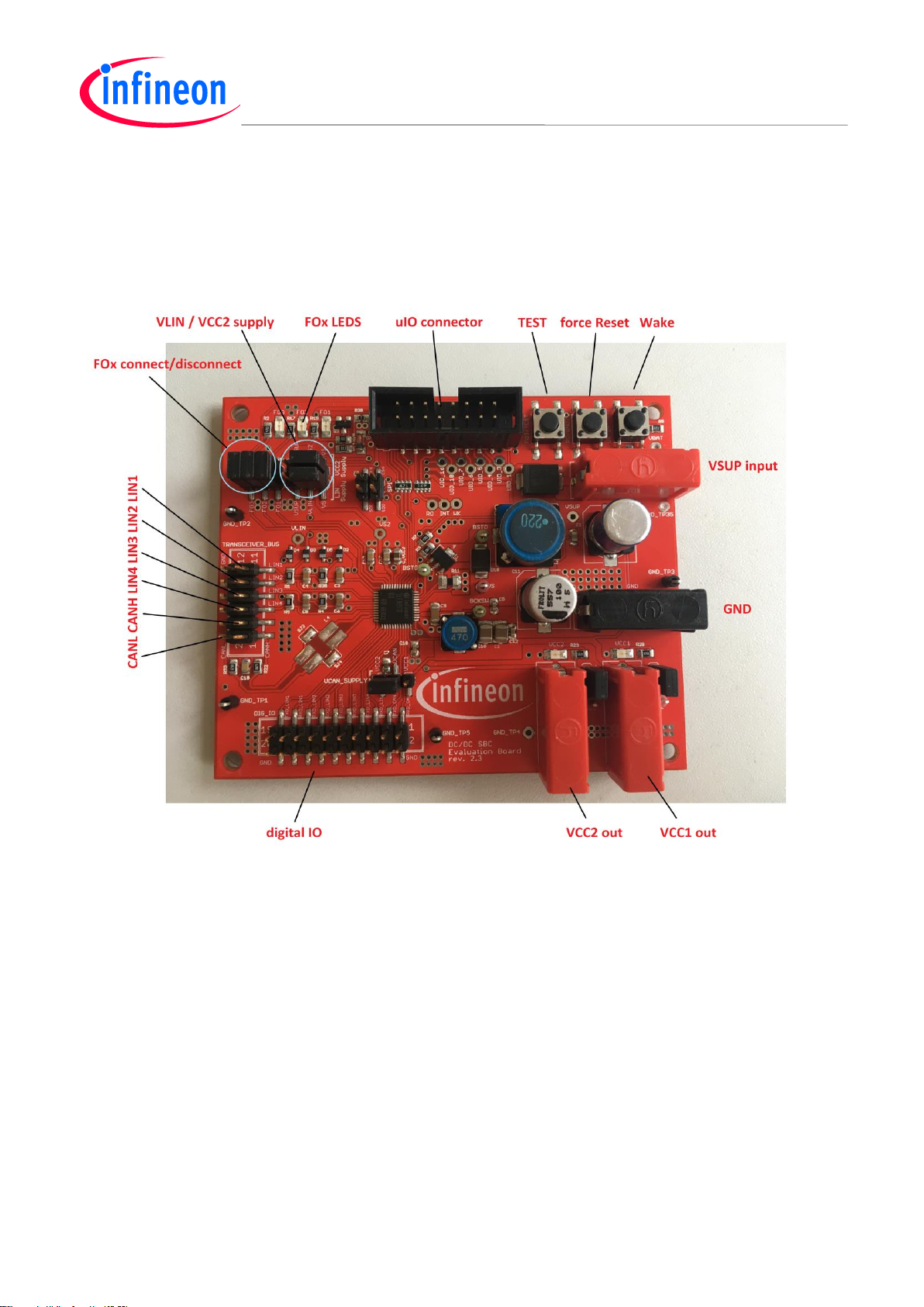
1. Evaluation Board Overview
There are 4 banana sockets, 5 LEDs, three buttons, one connector for the uIO and a set of headers for
jumper configuration in the evaluation board. The functionalites will be explained in the next chapters. The
distribution of these elements in the board can be observed in the following figure:
2. Banana Sockets
The SBC is usually supplied through the VSUP input and GND banana sockets.
The VCC1 output (5 V or 3.3 V, depending on the SBC’s version) and VCC2 (5 V) banana sockets provide
the regulated voltages from the SBC. The voltages VCC1 and VCC2 are used to supply the VCC1 and VCC2
supply indication LEDs which can be disconnected via the jumpers directly next to the banana outputs of
VCC1 and VCC2.
.
Page 5
TLE9273QX Evaluation Board
Getting Started
TLE9273QXEvaluation Board 5 Rev 1.0, Dec 2018
3. Buttons
In the upper right corner there are three buttons.
Test Button for enabling test mode (press during SBC Init-Mode when sending arbitrary SPI command)
Reset Force this button is connected in parallel to RO output of SBC and will connect RO line to GND
when pressing to force a low signal on RO
Wake this buttons will do a voltage transition on the wake input of SBC to trigger an external wake
4. LEDs
In the upper left corner are 3 LEDs to indicate the state of the Fail-Outputs. The LEDs can be disconnected
via the jumper directly under the LEDs. There are also two indication LEDs for the status of VCC1 and VCC2
(see behind the banana sockets for VCC1 and VCC2) which can be also disconnected via the jumpers directly
next to the banana connectors of VCC1 and VCC2
5. Connectors
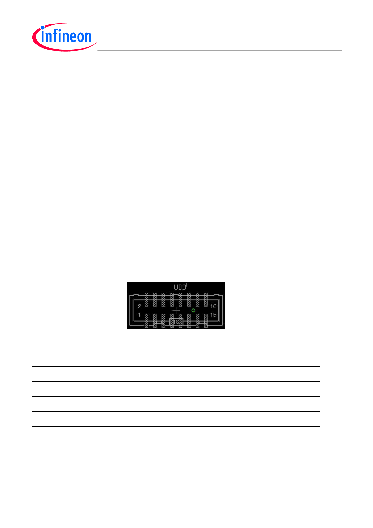
5.1. uIO Connector
The uIO Connector is used for connecting to the uIO stick, but can be also used to access the uC
interfacing pins. The pin distribution of the connector is shown in the following figure:
Pin
Functionality
Pin
Functionality
1
NC 2 GND
3
NC 4 NC 5 NC 6 VS_UIO
7
NC 8 INTN
9
CSN
10
NC
11
CLK
12
FO_UC
13
SDO
14
RSTN
15
SDI
16
ADC_UIO
Page 6
TLE9273QX Evaluation Board
Getting Started
TLE9273QXEvaluation Board 6 Rev 1.0, Dec 2018
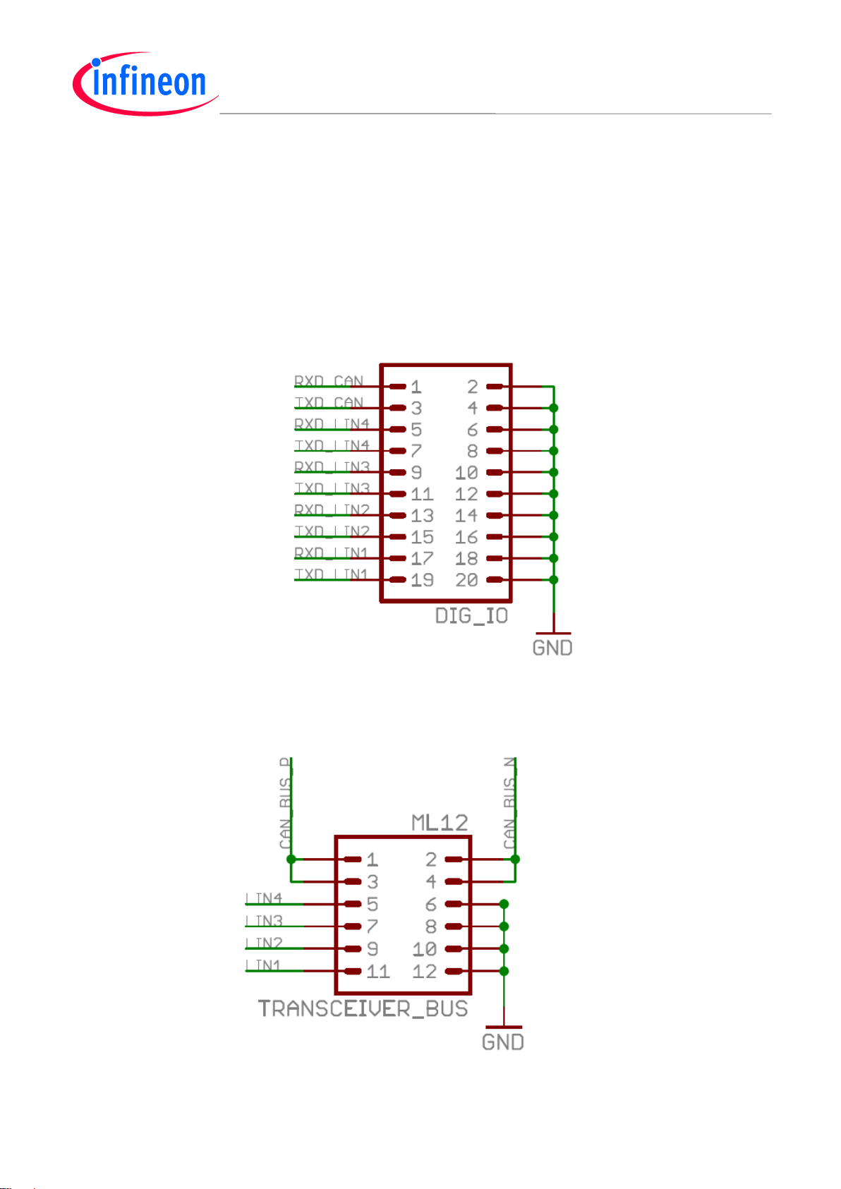
5.2. Digital IO Connectors
This connector can be used to access the RXD and TXD pins of the appropriate CAN and LIN transceivers
5.3. Transceiver Connectors
Those connectors can be used to connect to the transceiver outputs LIN1-LIN4 and to CAN.
Page 7

TLE9273QX Evaluation Board
Getting Started
TLE9273QXEvaluation Board 7 Rev 1.0, Dec 2018
6. Jumper Configurations
6.1. FO connect / disconnect jumpers
The approbriate FOx LEDs can be connected / disconnected from / to the FOx pins to indicate its status. Also
the jumpers can be used to connect an external fail circuitry.
Page 8

TLE9273QX Evaluation Board
Getting Started
TLE9273QXEvaluation Board 8 Rev 1.0, Dec 2018
6.2. VCC2 / VLIN jumpers
Those jumpers are located directly next to the jumpers of the fail outputs LEDs (see overview picture).
Depending on the configuration you can select the input supply of VCC2 regulator and the VLIN supply to
either VSUP (which is directly the banana socket input) or to VS (which is the ouput of boost-converter).
Page 9

TLE9273QX Evaluation Board
Getting Started
TLE9273QXEvaluation Board 9 Rev 1.0, Dec 2018
6.3. VCAN jumper
This jumper can be used to select the supply of the VCAN input. It can be connected either to VCC1 or
VCC2. VCAN must be supplied with 5V. Therefore – in case of DCDC SBC V33 type, this jumper must be
connected to VCC2.
.
Page 10

TLE9273QX Evaluation Board
Getting Started
TLE9273QXEvaluation Board 10 Rev 1.0, Dec 2018
7 Usage of ConfigWizard
Please connect your uIO stick to the uIO interface header and supply the evaluation board with e.g. 12V.
After this, please open “Config Wizard for SBC” inside Infineon Toolbox and select “TLE9273”. In case it has
problems to connect please refer to the uIO stick user manual which can be also downloaded under
http://www.infineon.com/SBC
Page 11

TLE9273QX Evaluation Board
Getting Started
TLE9273QXEvaluation Board 11 Rev 1.0, Dec 2018
After this, when the user interface is opening, then the SBC should be in SBC normal mode and SPI should be
accessable. This is indicated by green status flags.
All functionalities of the SBC are live controllable then by just clicking or selecting the appropriate functions.
Page 12

TLE9273QX Evaluation Board
Getting Started
TLE9273QXEvaluation Board 12 Rev 1.0, Dec 2018
8 Additional Information
For further information you may contact http://www.infineon.com or your regional FAE.
Page 13

Edition 2016-07-06
Published by
Infineon Technologies AG
81726 Munich, Germany
© 2018 Infineon Technologies AG
All Rights Reserved.
LEGAL DISCLAIMER
THE INFORMATION GIVEN IN THIS APPLICATION NOTE IS GIVEN AS A HINT FOR THE
IMPLEMENTATION OF THE INFINEON TECHNOLOGIES COMPONENT ONLY AND SHALL NOT BE
REGARDED AS ANY DESCRIPTION OR WARRANTY OF A CERTAIN FUNCTIONALITY, CONDITION OR
QUALITY OF THE INFINEON TECHNOLOGIES COMPONENT. THE RECIPIENT OF THIS APPLICATION
NOTE MUST VERIFY ANY FUNCTION DESCRIBED HEREIN IN THE REAL APPLICATION. INFINEON
TECHNOLOGIES HEREBY DISCLAIMS ANY AND ALL WARRANTIES AND LIABILITIES OF ANY KIND
(INCLUDING WITHOUT LIMITATION WARRANTIES OF NON-INFRINGEMENT OF INTELLECTUAL
PROPERTY RIGHTS OF ANY THIRD PARTY) WITH RESPECT TO ANY AND ALL INFORMATION GIVEN IN
THIS APPLICATION NOTE.
Information
For further information on technology, delivery terms and conditions and prices, please contact the nearest
Infineon Technologies Office (www.infineon.com).
Warnings
Due to technical requirements, components may contain dangerous substances. For information on the types in
question, please contact the nearest Infineon Technologies Office.
Infineon Technologies components may be used in life-support devices or systems only with the express written
approval of Infineon Technologies, if a failure of such components can reasonably be expected to cause the
failure of that life-support device or system or to affect the safety or effectiveness of that device or system. Life
support devices or systems are intended to be implanted in the human body or to support and/or maintain and
sustain and/or protect human life. If they fail, it is reasonable to assume that the health of the user or other
persons may be endangered.
Page 14

w w w . i n f i n e o n . c o m
Published by Infineon Technologies AG
Page 15

Page 16

Page 17

 Loading...