

N
Netz-Gleichrichterdiode
Rectifier Diode
Datenblatt / Data sheet
D5809N
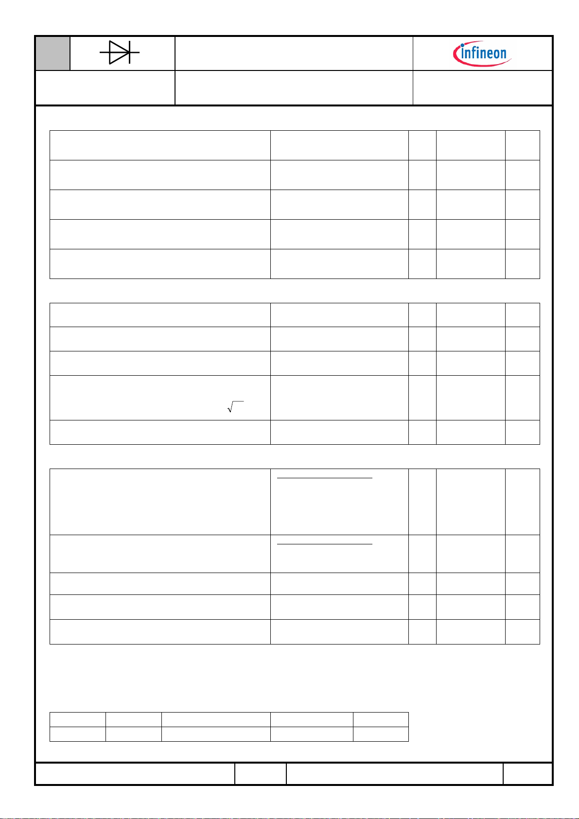
Elektrische Eigenschaften / Electrical properties
Höchstzulässige Werte / maximum rated values
Periodische Spitzensperrspannung
Kenndaten
repetitive peak reverse voltages
Elektrische Eigenschaften
Durchlaßstrom-Grenzeffektivwert
maximum RMS on-state current
Dauergrenzstrom
average on-state current
Stoßstrom-Grenzwert
surge current
Grenzlastintegral
I²t-value
Charakteristische Werte / Characteristic values
Durchlaßspannung
on-state voltage
Schleusenspannung
threshold voltage
Ersatzwiderstand
slope resistance
Durchlaßkennlinie 2000 A ≤ iF ≤ 28000 A
on-state characteristic
Sperrstrom
reverse current
FFF
iD)1i(lnCiBAv ⋅++⋅+⋅+=
F
= -40°C... T
T
vj
I
= 58 °C
T
C
= 130 °C
T
C
Tvj = 25 °C, tP = 10 ms
= Tvj max, tP = 10 ms
T
vj
Tvj = 25 °C, tP = 10 ms
T
= Tvj max, tP = 10 ms
vj
Tvj = T
vj max
= T
T
vj
vj max
Tvj = T
vj max
Tvj = T
vj max
T
= T
vj
vj max
Tvj = T
vj max
vj max
, iF = 18,0 kA
, iF = 6,0 kA
V
r
A=
, vR = V
RRM
V
400
RRM
9100 A
FRMSM
I
5800
FAVM
I
81000
FSM
I²t 32800
v
F
(TO)
0,04
T
iR
B=
C=
D=
max.
max.
max.
600
3000A A
70000
24500
1,47
0,92V V
4,617E-01
2,002E-05
7,441E-03
4,190E-03
100 mA
V
V
A 1)
A
10³A²s
10³A²s
0,7 V
mΩ
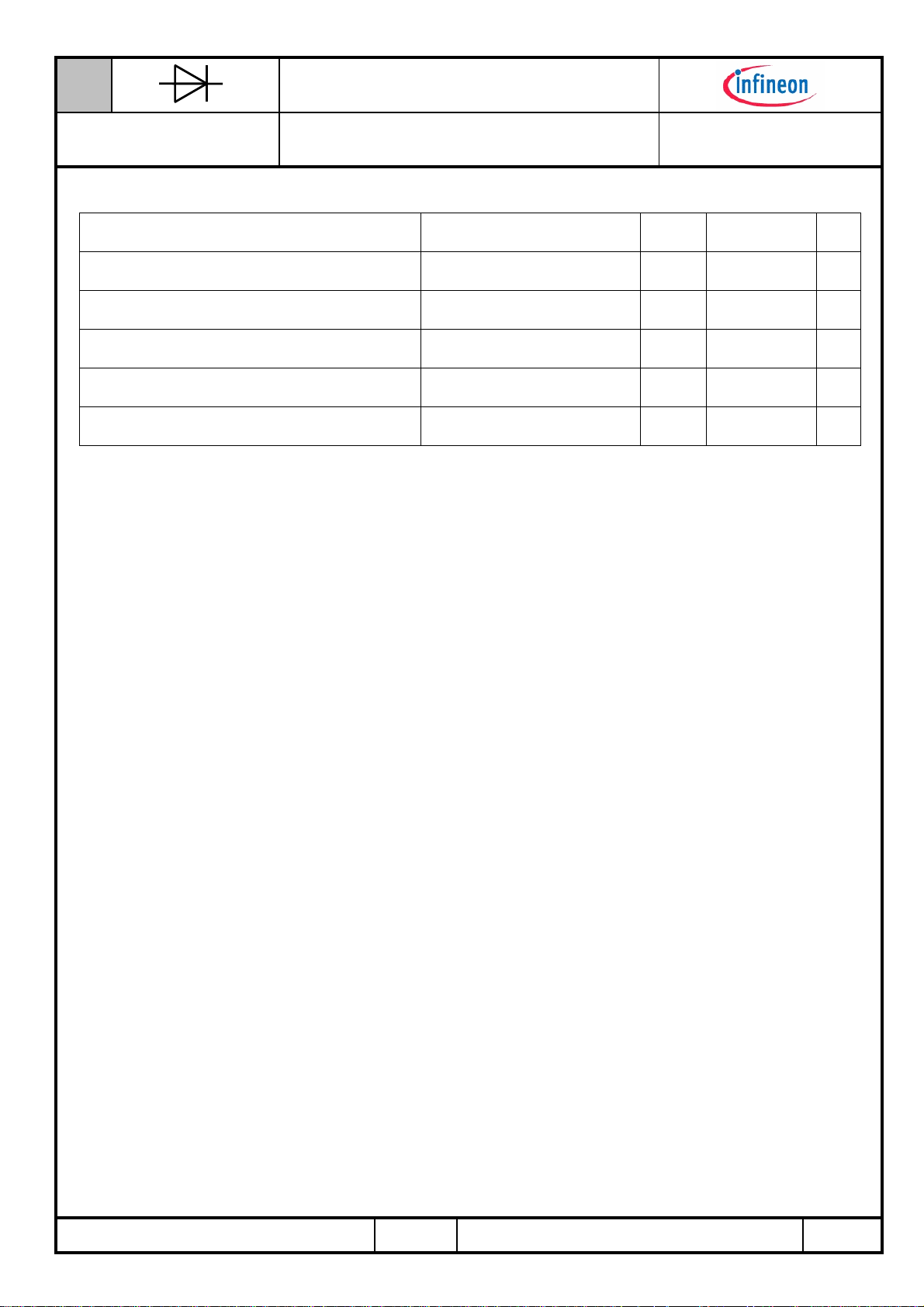
Thermische Eigenschaften / Thermal properties
Innerer Wärmewiderstand
thermal resistance, junction to case
Thermische Eigenschaften
Übergangs-Wärmewiderstand
thermal resistance, case to heatsink
Höchstzulässige Sperrschichttemperatur
maximum junction temperature
Betriebstemperatur
operating temperature
Lagertemperatur
storage temperature
1) Gehäusegrenzstrom I
= 32kA (50Hz Sinushalbwelle) / Peak case non ruptire current I
RSM(Case)
prepared by:
approved by: J.Przybilla
H.Sandmann date of publication: 2007-10-22
MA2-BE / 27 May 1994 , R.Jörke
A 22/94
Kühlfläche / cooling surface
beidseitig / two-sided, θ = 180°sin
beidseitig / two-sided, DC
Anode / anode, θ = 180°sin
Anode / anode, DC
Kathode / cathode, θ = 180°sin
Kathode / cathode, DC
Kühlfläche / cooling surface
beidseitig / two-sided
einseitig / single-sided
T
RSM(Case)
revision: 1
= 32kA (50Hz sinusoidal half wave)
R
R
T
T
thJC
thCH
vj max
c op
stg
max.
max.
max.
max.
max.
max.
-40...+150 °C
-40...+150 °C
max.
max.
Seite/page
0,0166
0,0160
0,0326
0,0320
0,0326
0,0320
0,0025
0,0050
180
°C/W
°C/W
°C/W
°C/W
°C/W
°C/W
°C/W
°C/W
°C
1/8
N
Netz-Gleichrichterdiode
Rectifier Diode
Datenblatt / Data sheet
D5809N
Mechanische Eigenschaften / Mechanical properties
Gehäuse, siehe Anlage
case, see annex
Si-Element mit Druckkontakt
Si-pellet with pressure contact
Anpreßkraft
clamping force
Gewicht
weight
Kriechstrecke
creepage distance
Schwingfestigkeit
vibration resistance
Mechanische Eigenschaften
Seite 3
F 30...60 kN
G typ. 530 g
40 mm
f = 50 Hz 50 m/s²
page 3
Mit diesem Datenblatt werden Halbleiterbauelemente spezifiziert, jedoch keine Eigenschaften zugesichert. Sie gilt in
Verbindung mit den zugehörigen technischen Erläuterungen.
This data sheet specifies semiconductor devices, but promises no characteristics. It is valid in combination with the belonging
technical notes.
MA2-BE / 27 May 1994 , R.Jörke
A 22/94
Seite/page
2/8
N
Netz-Gleichrichterdiode
Rectifier Diode
Datenblatt / Data sheet
D5809N
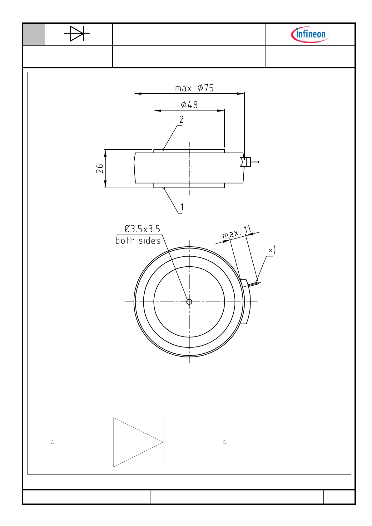
Maßbild
Maßbild
x) Pumpröhrchen (isoliert betreiben!), evacuation pipe (keep insulated!)
12
MA2-BE / 27 May 1994 , R.Jörke
A 22/94
1: Anode/
Anode
2: Kathode/
Cathode
Seite/page
3/8
N
−
=
τ
Netz-Gleichrichterdiode
Rectifier Diode
Datenblatt / Data sheet
D5809N
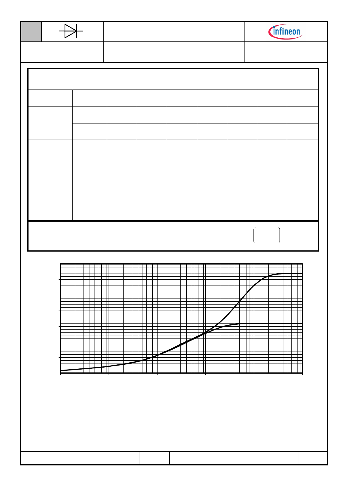
Analytische Elemente des transienten Wärmewiderstandes Z
Transienter Wärmewiderstand
Kühlung /
Cooling
beidseitig
Analytical elements of transient thermal impedance Z
Pos. n 1 2 3 4 5 6 7
R
[°C/W] 0,000045 0,000909 0,000852 0,001994 0,00473 0,00747 -
thn
two-sided
τ
[s]
n
R
[°C/W]
thn
anodenseitig
anode-sided
τ
[s]
n
R
[°C/W] 0,000049
thn
kathodenseitig
cathode-sided
τ
[s]
n
Analytische Funktion / Analytical function:
für DC
thJC
thJC
for DC
0,000048 0,000843 0,005420 0,057200 0,22900 1,13000 -
0,000049
0,000049
0,000049
0,001061
0,000969
0,001061
0,000969
0,001180
0,010700
0,001180
0,010700
0,006790
0,169000
0,006790
0,169000
0,00442
2,79000
0,00442
2,79000
n
max
Σ
n=1
thnthJC
0,01850
6,11000
0,01850
6,11000
-t
n
e1RZ
-
-
-
-
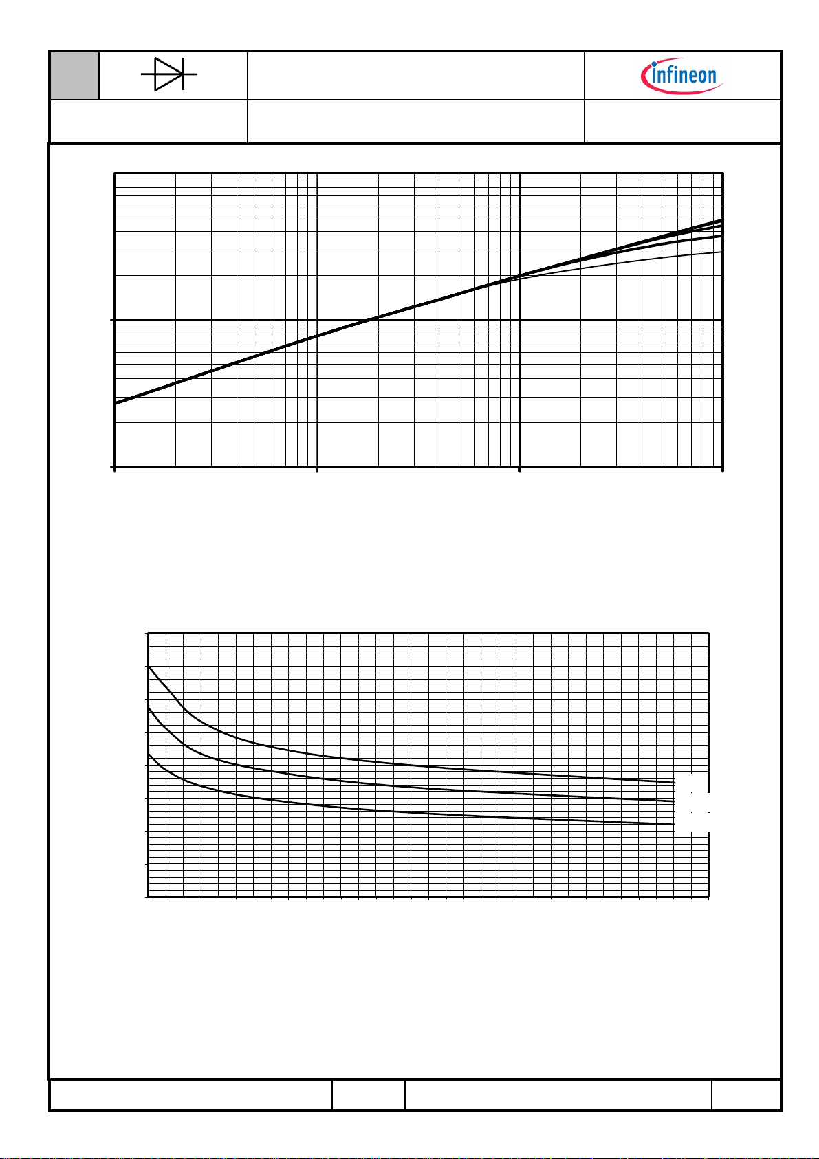
0,035
0,030
0,025
0,020
[°C/W]
0,015
thJC
Z
0,010
0,005
0,000
0,001 0,01 0,1 1 10 100
Transienter innerer Wärmewiderstand für DC / Transient thermal impedance for DC
Z
thJC
a - Anodenseitige Kühlung / Anode-sided cooling
b - Beidseitige Kühlung / Two-sided cooling
c - Kathodenseitige Kühlung / Cathode-sided cooling
t [s]
= f(t)
c
a
b
MA2-BE / 27 May 1994 , R.Jörke
A 22/94
Seite/page
4/8
N
Netz-Gleichrichterdiode
Rectifier Diode
Datenblatt / Data sheet
D5809N
Erhöhung des Z
Rise of Z
Diagramme
th DC
Diagramme
Kühlung / Cooling
beidseitig
two-sided
anodenseitig
anode-sided
kathodenseitig
cathode-sided
40.000
bei sinus- und rechteckförmigen Strömen für unterschiedliche Stromflusswinkel Θ
th DC
for sinewave and rectangular current for different current conduction angles Θ
∆Z
th Θ rec
[°C/W]
∆Z
th Θ sin
[°C/W]
∆Z
th Θ rec
[°C/W]
∆Z
th Θ sin
[°C/W]
∆Z
th Θ rec
[°C/W]
∆Z
th Θ sin
[°C/W]
∆Z
Θ = 180° Θ = 120° Θ = 90° Θ = 60° Θ = 30°
0,00188
0,00060
0,00185
0,00053
0,00185
0,00053
Z
th Θ rec
Z
th Θ sin
th Θ rec
= Z
= Z
/ ∆Z
0,00332
0,00110
0,00326
0,00101
0,00326
0,00101
th DC
th DC
th Θ sin
+ ∆Z
+ ∆Z
th Θ rec
th Θ sin
0,00458
0,00186
0,00455
0,00179
0,00455
0,00179
0,00676
0,00347
0,00679
0,00349
0,00679
0,00349
0,01150
0,00790
0,01159
0,00809
0,01159
0,00809
30.000
[A]
20.000
F
i
10.000
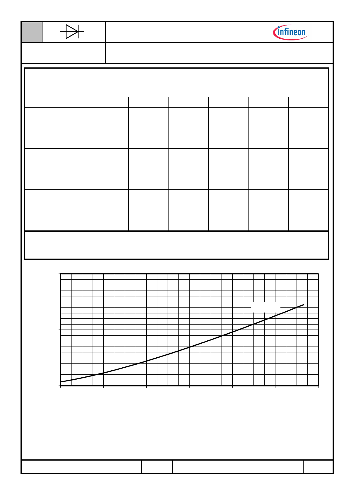
Durchlasskennlinie
T
= T
vj
vj max
0
0,7 0,9 1,1 1,3 1,5 1,7 1,9
[V]
V
F
Grenzdurchlasskennlinie / Limiting on-state characteristic iF = f(vF)
T
= Tvj
vj
max
MA2-BE / 27 May 1994 , R.Jörke
A 22/94
Seite/page
5/8

N
Netz-Gleichrichterdiode
Rectifier Diode
Datenblatt / Data sheet
D5809N
12000
10000
8000
[W]
6000
FAV
P
4000
2000
Durchlassverluste
a
b
c
d
e
f
0
0 1000 2000 3000 4000 5000 6000 7000 8000 9000 10000
[A]
I
FAV
Durchlassverlustleistung / On-state power loss P
Beidseitige Kühlung / Two-sided cooling
Parameter:
a - DC
b - sin 180°el (M 1 , M 2 , B 2)
c - rec 120° el (B 6 , M 3 , M 3.2)
d - rec 60°el (M 6)
e - sin 60°el (M 1 , M 2 , B 2 Gegenspannungs belastung / Reverse voltage load)
f - sin 30°el (M 1 , M 2 , B 2 Gegenspannungs belastung / Reverse voltage load)
= f(I
FAV
)
FAV
Tc beidseitig
Parameter:
a - DC
b - sin 180°el (M 1 , M 2 , B 2)
c - rec 120° el (B 6 , M 3 , M 3.2)
d - rec 60°el (M 6)
e - sin 60°el (M 1 , M 2 , B 2 Gegenspannungs belastung / Reverse voltage load)
f - sin 30°el (M 1 , M 2 , B 2 Gegenspannungs belastung / Reverse voltage load)
[°C]
C
180
160
140
120
100
T
80
60
40
d bef
c
20
0 1000 2000 3000 4000 5000 6000 7000 8000 9000 10000
[A]
I
FAV
Höchstzulässige Gehäusetemperatur / Maximum allowable case temperature T
Beidseitige Kühlung / Two-sided cooling
= f(I
C
FAV
)
a
MA2-BE / 27 May 1994 , R.Jörke
A 22/94
Seite/page
6/8
N
Netz-Gleichrichterdiode
Rectifier Diode
10000
[µAs]
r
Q
1000
100
0,1 1 10 100
Datenblatt / Data sheet
D5809N
Qr Diagramm
-di/dt [A/µs]
Sperrverzögerungsladung / Recovered charge
Qr =f(-di/dt)
T
= T
vj
RC-Glied / RC-Network: R = 2,7Ω, C = 1,5µF
vjmax , vR
≤ 0,5 V
RRM
, v
RM
= 0,8 V
RRM
iFM =
6200A
800A
400A
200A
80
70
60
50
[kA]
40
F(OV)M
I
30
20
10
0
1 3 5 7 9 11 13 15 17
Anzahl der Pulse bei 50Hz Sinus Halbwellen
Number of pulses of 50Hz sinusoidal half waves
Typische Abhängigkeit des Grenzstromes I
Halbwellen bei 50Hz. Parameter: Rückwärtsspannung V
Typical dependency of maximum overload on-state current I
sinusoidal half waves at 50Hz. Parameter: peak reverse voltage V
I
= f (pulses, VRM) ; Tvj = T
F(OV)M
von der Anzahl für eine Folge von Sinus
F(OV)M
as a number of a sequence of
F(OV)M
vj max
RM
RM
0-50V
0,33 VRRM
0,67 VRRM
MA2-BE / 27 May 1994 , R.Jörke
A 22/94
Seite/page
7/8
N
Netz-Gleichrichterdiode
Rectifier Diode
Datenblatt / Data sheet
D5809N
Disclaimer
Nutzungsbedingungen
Die in diesem Produktdatenblatt enthaltenen Daten sind ausschließlich für technisch geschultes Fachpersonal bestimmt. Die Beurteilung
der Geeignetheit dieses Produktes für die von Ihnen anvisierte Anwendung sowie die Beurteilung der Vollständigkeit der bereitgestellten
Produktdaten für diese Anwendung obliegt Ihnen bzw. Ihren technischen Abteilungen.
In diesem Produktdatenblatt werden diejenigen Merkmale beschrieben, für die wir eine liefervertragliche Gewährleistung übernehmen. Eine
solche Gewährleistung richtet sich ausschließlich nach Maßgabe der im jeweiligen Liefervertrag enthaltenen Bestimmungen. Garantien
jeglicher Art werden für das Produkt und dessen Eigenschaften keinesfalls übernommen.
Sollten Sie von uns Produktinformationen benötigen, die über den Inhalt dieses Produktdatenblatts hinausgehen und insbesondere eine
spezifische Verwendung und den Einsatz dieses Produktes betreffen, setzen Sie sich bitte mit dem für Sie zuständigen Vertriebsbüro in
Verbindung (siehe www.eupec.com, Vertrieb&Kontakt). Für Interessenten halten wir Application Notes bereit.
Aufgrund der technischen Anforderungen könnte unser Produkt gesundheitsgefährdende Substanzen enthalten. Bei Rückfragen zu den in
diesem Produkt jeweils enthaltenen Substanzen setzen Sie sich bitte ebenfalls mit dem für Sie zuständigen Vertriebsbüro in Verbindung.
Sollten Sie beabsichtigen, das Produkt in Anwendungen der Luftfahrt, in gesundheits- oder lebensgefährdenden oder lebenserhaltenden
Anwendungsbereichen einzusetzen, bitten wir um Mitteilung. Wir weisen darauf hin, dass wir für diese Fälle
- die gemeinsame Durchführung eines Risiko- und Qualitätsassessments;
- den Abschluss von speziellen Qualitätssicherungsvereinbarungen;
- die gemeinsame Einführung von Maßnahmen zu einer laufenden Produktbeobachtung dringend
empfehlen und gegebenenfalls die Belieferung von der Umsetzung solcher Maßnahmen abhängig
machen.
Soweit erforderlich, bitten wir Sie, entsprechende Hinweise an Ihre Kunden zu geben.
Inhaltliche Änderungen dieses Produktdatenblatts bleiben vorbehalten.
Terms & Conditions of usage
The data contained in this product data sheet is exclusively intended for technically trained staff. You and your technical departments will
have to evaluate the suitability of the product for the intended application and the completeness of the product data with respect to such
application.
This product data sheet is describing the characteristics of this product for which a warranty is granted. Any such warranty is granted
exclusively pursuant the terms and conditions of the supply agreement. There will be no guarantee of any kind for the product and its
characteristics.
Should you require product information in excess of the data given in this product data sheet or which concerns the specific application of
our product, please contact the sales office, which is responsible for you (see www.eupec.com, sales&contact). For those that are
specifically interested we may provide application notes.
Due to technical requirements our product may contain dangerous substances. For information on the types in question please contact the
sales office, which is responsible for you.
Should you intend to use the Product in aviation applications, in health or live endangering or life support applications, please notify. Please
note, that for any such applications we urgently recommend
- to perform joint Risk and Quality Assessments;
- the conclusion of Quality Agreements;
- to establish joint measures of an ongoing product survey, and that we may make delivery depended on
the realization of any such measures.
If and to the extent necessary, please forward equivalent notices to your customers.
Changes of this product data sheet are reserved.
MA2-BE / 27 May 1994 , R.Jörke
A 22/94
Seite/page
8/8
 Loading...