

European PowerSemiconductor and
Electronics Company
GmbH + Co. KG
Leistungsgleichrichterdioden
Power Rectifier Diodes
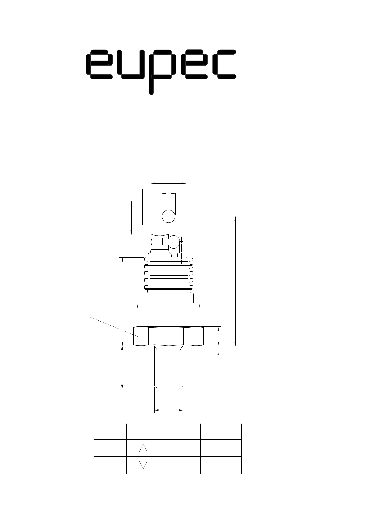
D 126 A
15
6,5
14
5,5
SW27
D126A
±2
58
40
8
2
18
M12
Schaltsymbol
Kathode AnodeTyp
Anschluß-
lasche
Gehäuse-
boden
D126B
Gehäuse-
boden
Anschluß-
lasche
VWK July 1996

D 126 A 45
Elektrische Eigenschaften Electrical properties
Höchstzulässige Werte Maximum rated values
Periodische Spitzensperrspannung repetitive peak reverse voltage tvj = -40°C... t
vj max
Stoßsperrverlustleistung surge reverse power dissipation tvj = 25 °C, tw = 20 µs P
Durchlaßstrom-Grenzeffektivwert RMS forward current I
Dauergrenzstrom mean forward current tc = 100 °C I
tc = 35 °C 200 A
Stoßstrom-Grenzwert surge forward current tvj = 25°C, tp = 10 ms I
tvj = t
, tp = 10 ms 2,3 kA
vj max
Grenzlastintegral I2 t-value tvj = 25°C, tp = 10 ms I2 t 43,5 kA2s
tvj = t
, tp = 10 ms 26,45 kA2s
vj max
Charakteristische Werte Characteristic values
Durchlaßspannung on-state voltage tvj = t
Schleusenspannung threshold voltage tvj = t
Ersatzwiderstand slope resistance tvj = t
Sperrstrom reverse current tvj = t
Durchbruchspannung breakdown voltage tvj = +25 °C... t
, iF = 600 A V
vj max
vj max
vj max
, VR = V
vj max
RRM
vj max
V
RRM
RSM
FRMSM
FAVM
FSM
T
V
T(TO)
r
T
i
R
V
(BR)
4500 V
10 kW
315 A
126 A
2,95 kA
max. 2,8 V
0,86 V
3,2 mΩ
max. 30 mA
min. 4,8 kV
Thermische Eigenschaften Thermal properties
Innerer Widerstand thermal resistance, junction Θ = 180° sin R
thJC
max. 0,257 °C/W
to case DC max. 0,250 °C/W
Übergangs-Wärmewiderstand thermal resistance,case to heatsink R
Höchstzul.Sperrschichttemperatur max. junction temperature t
Betriebstemperatur operating temperature t
Lagertemperatur storage temperature t
thCK
vj max
c op
stg
max. 0,04 °C/W
160 °C
-40...+160 °C
-40...+160 °C
Mechanische Eigenschaften Mechanical properties
Si-Element mit Druckkontakt Si-pellet with pressure contact ∅ = 21 mm
Anzugsdrehmoment tightening torque Gehäuseform/case design C M 20 Nm
Gewicht weight G typ. 110 g
Kriechstrecke creepage distance 25 mm
Feuchteklasse humidity classification DIN 40040 C
Schwingfestigkeit vibration resistance f = 50 Hz 50 m/s
Maßbild outline Seite/page
Polarität polarity Anode=Gehäuse/case
2
D 126 A
800
700
i
[A]
F
600
500
400
300
200
100
0
0,5 1,0 1,5 2,0 2,5 3,0 3,5
v
[V]
D126A_1
F
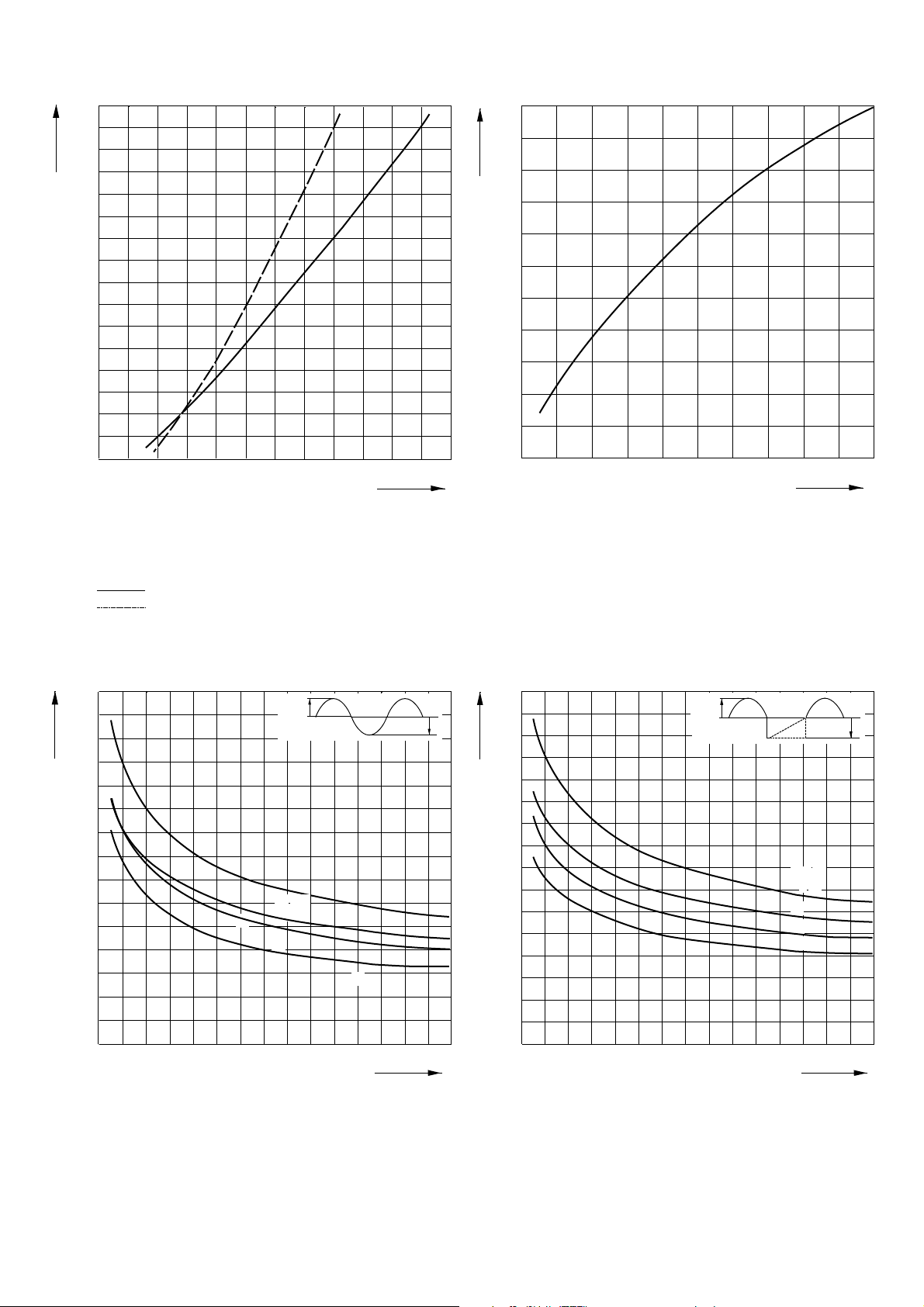
Bild/Fig. 1
Grenzdurchlaßkennlinie
Limiting forward characteristic iF = f (vF)
tvj = 160 °C
= 25 °C
t
vj
⌠
i²dt
⌡
(normiert)
1,0
0,9
0,8
0,7
0,6
0,5
0 1 2 3 4 5 6 7 8 9 10
t
[ms]
D126A_4
p
Bild / Fig. 2
Normiertes Grenzlastintegral / Normalized i²t
∫i²dt = f(tp)
I
I
F(0V)M
I
F(0V)M
3
[kA ]
2
1a
1b
+
1c
+
2a
1
0
D126A_5
0,1
2b
Bild / Fig. 3
Grenzstrom / Maximum overload forward current IF(0V)M = f(t)
1 - IFAV(vor) = 0 A; tvj = tC = 25 °C
2 - IFAV(vor) = 126 A; tC = 100 °C; tvj = 160 °C
a - vR ≤ 50 V
b - vR = 0,5 VRRM
c - vR = 0,8 VRRM
v
R
2c
0,2 0,3
t
[s]
I
I
F(0V)M
I
F(0V)M
3
[kA]
2
1
0
0
D126A_6
0,1
0,2
Bild / Fig. 4
Grenzstrom / Maximum overload forward current IF(0V)M = f(t)
1 - IFAV(vor) = 0 A; tvj = tC = 25 °C
2 - IFAV(vor) = 126 A; tC = 100 °C; tvj = 160 °C
a - vR ≤ 50 V
b - vR = 0,5 VRRM
c - vR = 0,8 VRRM
v
R
1a
1b1c+
+
2a
2b
2c
0,3
t
[s]
0,04
∆
R
thJC
[°C/W]
0,02
D 126 A
0
30
D126A_3
4
10
9
8
7
Θ
T
Q
[µAs]
Θ
T
Θ
T
60
90
120
Θ
[°el]
150
180
6
5
4
r
3
2
3
10
9
8
7
6
5
4
3
2
2
10
0,1
D126A_7
1
-diF/dt
[A]=
i
FM
320
160
80
40
20
10
10 100
[A/µs]
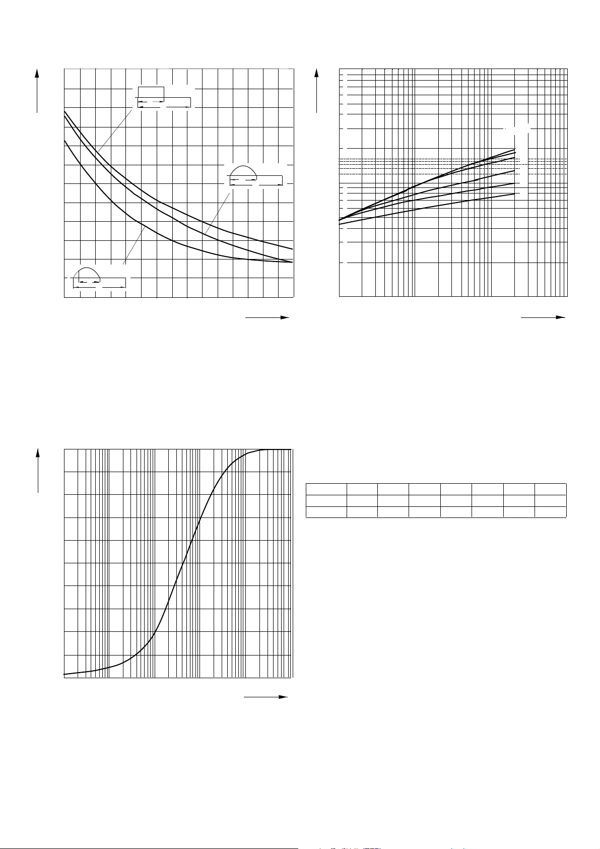
Bild / Fig. 5
Differenz zwischen den Wärmewiderständen
für Pulsstrom und DC
Difference between the values of thermal resistance for
pulse current and DC
Parameter: Stromkurvenform / Current waveform
0,25
0,20
Z
(th)JC
[°C/W]
0,15
0,10
0,05
Bild / Fig. 6
Sperrverzögerungsladung / Recovered charge Qr = f(-diF/dt)
tvj = tvjmax; vR ≤ 0,5 VRRM; VRM = 0,8 VRRM
Beschaltung / Snubber: C = 0,47 µF; R = 8,2 Ω
Parameter: Durchlaßstrom / Forward current iFM
Analytische Elemente des transienten Wärmewiderstandes ZthJC für DC
Analytical elements of transient thermal impedance ZthJC for DC
Pos. n
Rthn °C/W
tn [s]
1 2 3 4 5 6 7
0,000058
0,000167
0,003682
0,00154
0,00761
0,0102
0,0469
0,162
0,134
0,592
0,05775
4,09
Analytische Funktion / Analytical function:
max
n
ZthJC = Rthn(1-EXP(-t/τn))
Σ
n=1
0
-3
10
D126A_2
10
-2
10
-1
10
0
Bild / Fig. 7
Transienter innerer Wärmewiderstand
Transient thermal impedance ZthJC = f(t), DC
1 - Beidseitige Kühlung / Two-sided cooling
2 - Anodenseitige Kühlung / Anode-sided cooling
3 - Kathodenseitige Kühlung / Cathode-sided cooling
t [s]
10
1
10
2

Terms & Conditions of Usage
Attention
The present product data is exclusively subscribed to technically experienced
staff. This Data Sheet is describing the specification of the products for which a
warranty is granted exclusively pursuant the terms and conditions of the supply
agreement. There will be no guarantee of any kind for the product and its
specifications. Changes to the Data Sheet are reserved.
You and your technical departments will have to evaluate the suitability of the
product for the intended application and the completeness of the product data
with respect to such application. Should you require product information in
excess of the data given in the Data Sheet, please contact your local Sales Office
via “www.eupec.com / sales & contact”.
Warning
Due to technical requirements the products may contain dangerous substances.
For information on the types in question please contact your local Sales Office via
“www.eupec.com / sales & contact”.
 Loading...