

Page 1

Design Guide, Version 1.1, 8 August 2011
ICE2QRxx65/80x
Quasi Resonance CoolSET Design Guide
AN-PS0053
Power Management & Supply
N e v e r s t o p t h i n k i n g .
Page 2

Published by
Infineon Technologies AG
81726 Munich, Germany
© 2010 Infineon Technologies AG
All Rights Reserved.
Legal Disclaimer
The information given in this document shall in no event be regarded as a guarantee of
conditions or characteristics. With respect to any examples or hints given herein, any typical
values stated herein and/or any information regarding the application of the device,
Infineon Technologies hereby disclaims any and all warranties and liabilities of any kind,
including without limitation, warranties of non-infringement of intellectual property rights
of any third party.
Information
For further information on technology, delivery terms and conditions and prices, please
contact the nearest Infineon Technologies Office (www.infineon.com).
Warnings
Due to technical requirements, components may contain dangerous substances. For information
on the types in question, please contact the nearest Infineon Technologies Office.
Infineon Technologies components may be used in life-support devices or systems only with
the express written approval of Infineon Technologies, if a failure of such components can
reasonably be expected to cause the failure of that life-support device or system or to affect
the safety or effectiveness of that device or system. Life support devices or systems are
intended to be implanted in the human body or to support and/or maintain and sustain
and/or protect human life. If they fail, it is reasonable to assume that the health of the user
or other persons may be endangered.
Page 3

: ICE2QRxx65/80x Design Guide
8 August 2011 V1.1
V1.0
Subjects (major changes since last revision)
Add ICE2QR0665Z, ICE2QR1065Z, ICE2QR1765Z, ICE2QR4765Z, ICE2QR0665G,
ICE2QR1765G and ICE2QR4765GZ
Revise typo
ICE2QRxx65/80x Quasi Resonance CoolSET Design Guide
License to Infineon Technologies Asia Pacific Pte Ltd
Winson Wong
Winson.wong@infineon.com
Eric Kok
Eric.kok@infineon.com
AN-PS0053
We Listen to Your Comments
Any information within this document that you feel is wrong, unclear or missing at all?
Your feedback will help us to continuously improve the quality of this document.
Please send your proposal (including a reference to this document) to:
comments@infineon.com
Design Guide 3 8 August 2011
Page 4

Quasi-resonant CoolSET design guide
ICE2QRxx65/80x
Table of Contents
1 Introduction.......................................................................................................5
2 CoolSET description.........................................................................................5
2.1 Main features.......................................................................................................................5
2.2 Pin layout.............................................................................................................................5
2.3 Pin functions .......................................................................................................................6
2.3.1 ZC (Zero Crossing)..........................................................................................................6
2.3.2 FB (Feedback).................................................................................................................6
2.3.3 CS (Current Sensing) ......................................................................................................6
2.3.4 Drain................................................................................................................................6
2.3.5 VCC (Power supply)........................................................................................................6
2.3.6 GND (Ground) .................................................................................................................6
3 Overview of quasi-resonant flyback converter ..............................................6
4 Functional description and component design .............................................8
4.1 VCC Pre-Charging and Typical VCC Voltage During Start-up .......................................8
4.1.1 VCC Capacitor.................................................................................................................9
4.2 Soft-Start..............................................................................................................................9
4.3 Normal Operation..............................................................................................................10
4.3.1 Switch-on Determination ...............................................................................................10
4.3.2 Switch-off Determination ...............................................................................................11
4.4 Active Burst Mode Operation..........................................................................................11
4.4.1 Entering Active Burst Mode Operation..........................................................................11
4.4.2 During Burst Mode Operation........................................................................................12
4.4.3 Leaving Active Burst Mode............................................................................................13
4.5 Current sense....................................................................................................................13
4.6 Feedback ...........................................................................................................................13
4.7 Zero crossing ....................................................................................................................13
4.8 Protections........................................................................................................................15
4.9 Others ................................................................................................................................15
5 Typical application circuit..............................................................................15
6 Input Power Curves for Quasi Coolset 650V/800V.......................................16
7 PCB Layout Recommendation.......................................................................22
8 Product Portfolio Quasi Resonant CoolSET®...............................................22
9 Design Equations............................................................................................23
10 References ......................................................................................................24
Design Guide 4 8 August 2011
Page 5

Quasi-resonant CoolSET design guide
ICE2QRxx65/80x
1 Introduction
This design guide describes how to design quasi-resonant flyback converters using ICE2QRxx65/80x, which
is a new Quasi-resonant PWM CoolSET developed by Infineon Technologies
Firstly, the basic description of CoolSET will be given including the main features and Pin’s layout. Then an
overview of quasi-resonant flyback converter will be given, followed by the introduction of ICE2QRxx65/80x’s
functions and operations. A typical application example, input power curves, PCB layout recommendation,
product profolio and design equations will be given in the last part of this document.
2 CoolSET description
ICE2QRxxxx is a second generation quasi-resonant PWM CoolSET with power MOSFET and startup cell in a
single package optimized for off-line power supply applications such as LCD TV, and notebook adapter. The
digital frequency reduction with decreasing load enables a quasi-resonant operation till very low load. As a
result, the system average efficiency is significantly improved compared to conventional solutions. The active
burst mode operation enables ultra-low power consumption at standby mode operation and low output
voltage ripple. The numerous protection functions give a full protection of the power supply system in failure
situation. All of these make the ICE2QRxx65/80x an outstanding power CoolSET for quasi-resonant flyback
converter in the market.
In addition, numerous protection functions have been implemented in the CoolSET to protect the system and
customize the CoolSET for the chosen applications. All of these make the ICE2QRxx65/80x an outstanding
product for real quasi-resonant flyback converter in the market.
2.1 Main features
High voltage (650V/800V) avalanche rugged CoolMOS®with startup cell
Quasi-resonant operation
Load dependent digital frequency reduction
Active burst mode for light load operation
Built-in high voltage startup cell
Built-in digital soft-start
Cycle-by-cycle peak current limitation with built-in leading edge blanking time
Foldback Point Correction with digitalized sensing and control circuits
VCC undervoltage and overvoltage protection with Autorestart mode
Over Load /open loop Protection with Autorestart mode
Built-in Over temperature protection with Autorestart mode
Adjustable output overvoltage protection with Latch mode
Short-winding protection with Latch mode
Maximum on time limitation
Maximum switching period limitation
2.2 Pin layout
Figure 1 Pin configurations (top view), DIP-8 version; DIP-7 (Z) version; and DSO-12 (G) version;
Design Guide 5 8 August 2011
Page 6

Quasi-resonant CoolSET design guide
ICE2QRxx65/80x
2.3 Pin functions
2.3.1 ZC (Zero Crossing)
Three functions are incorporated at the ZC pin. First, during MOSFET off time, the de-magnetization of the
transformer is detected when the ZC voltage falls below V
off, an output overvoltage fault will be assumed if VZCis higher than V
MOSFET on time, a current depending on the bus voltage flows out of this pin. Information on this current is
then used to adjust the maximum current limit. More details on this function are provided in Section 4.
2.3.2 FB (Feedback)
Usually, an external capacitor is connected to this pin to smooth the feedback voltage. Internally, this pin is
connected to the PWM signal generator for switch-off determination (together with the current sensing signal),
and to the digital signal processing for the frequency reduction with decreasing load during normal operation.
Additionally, the openloop/overload protection is implemented by monitoring the voltage at this pin.
2.3.3 CS (Current Sensing)
This pin is connected to the shunt resistor for the primary current sensing externally and it is also used to
determine the PWM signal generator for switch-off (together with the feedback voltage) internally. Moreover,
short-winding protection is realised by monitoring the Vcsvoltage during on-time of the main power switch.
(100mv). Second, after the MOSFET is turned
ZCCT
(3.7V). Finally, during the
ZCOVP
2.3.4 Drain
This pin is connected to the drain of the 650V/800V CoolMOS®.
2.3.5 VCC (Power supply)
The VCC pin is the positive supply of the CoolSET and should be connected to auxiliary winding of the main
transformer.
2.3.6 GND (Ground)
This is the common ground of the CoolSET. Note that the current sense resistor ground should be connected
to bulk capacitor ground in order to avoid strong noise interruption.
3 Overview of quasi-resonant flyback converter
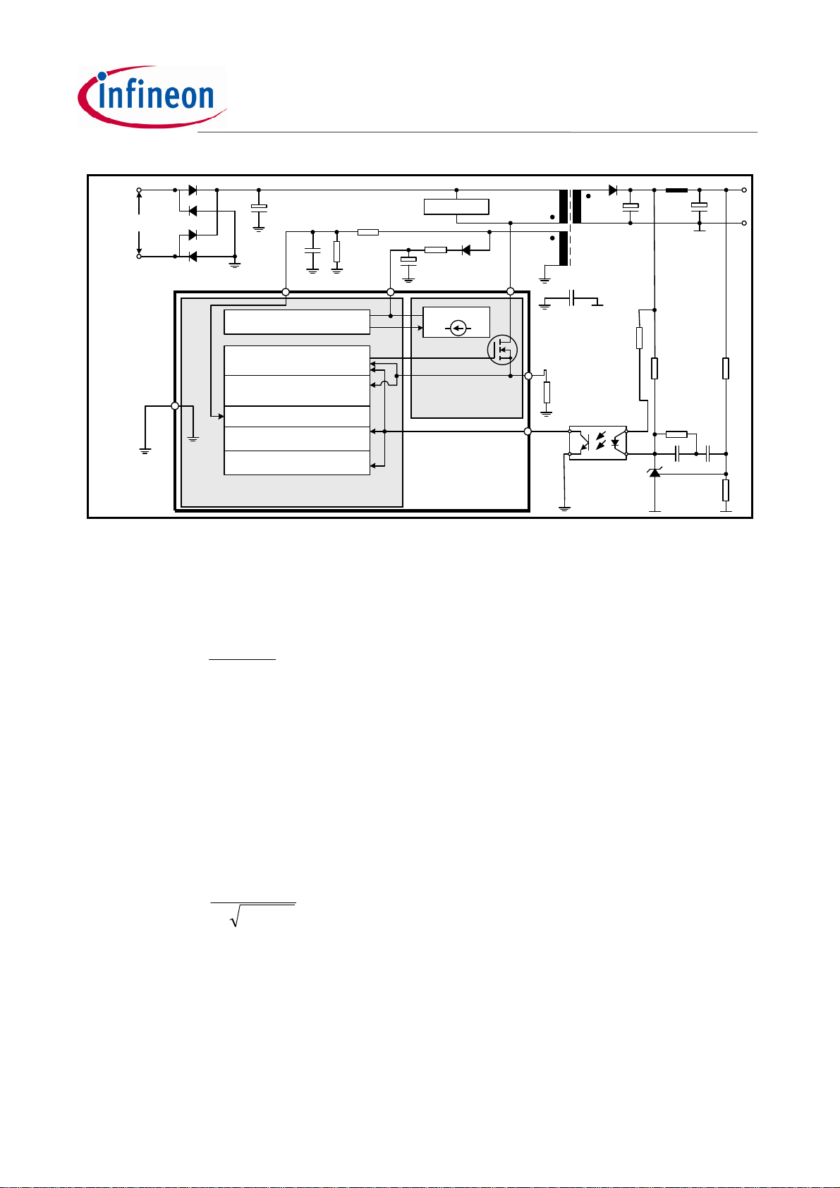
Figure 2 shows a typical application of ICE2QRxx65/80x in quasi-resonant flyback converter. In this
converter, the mains input voltage is rectified by the diode bridge and then smoothed by the capacitor C
where the bus voltage V
windings (here one secondary winding Ws), and one auxiliary winding Wa. When quasi-resonant control is
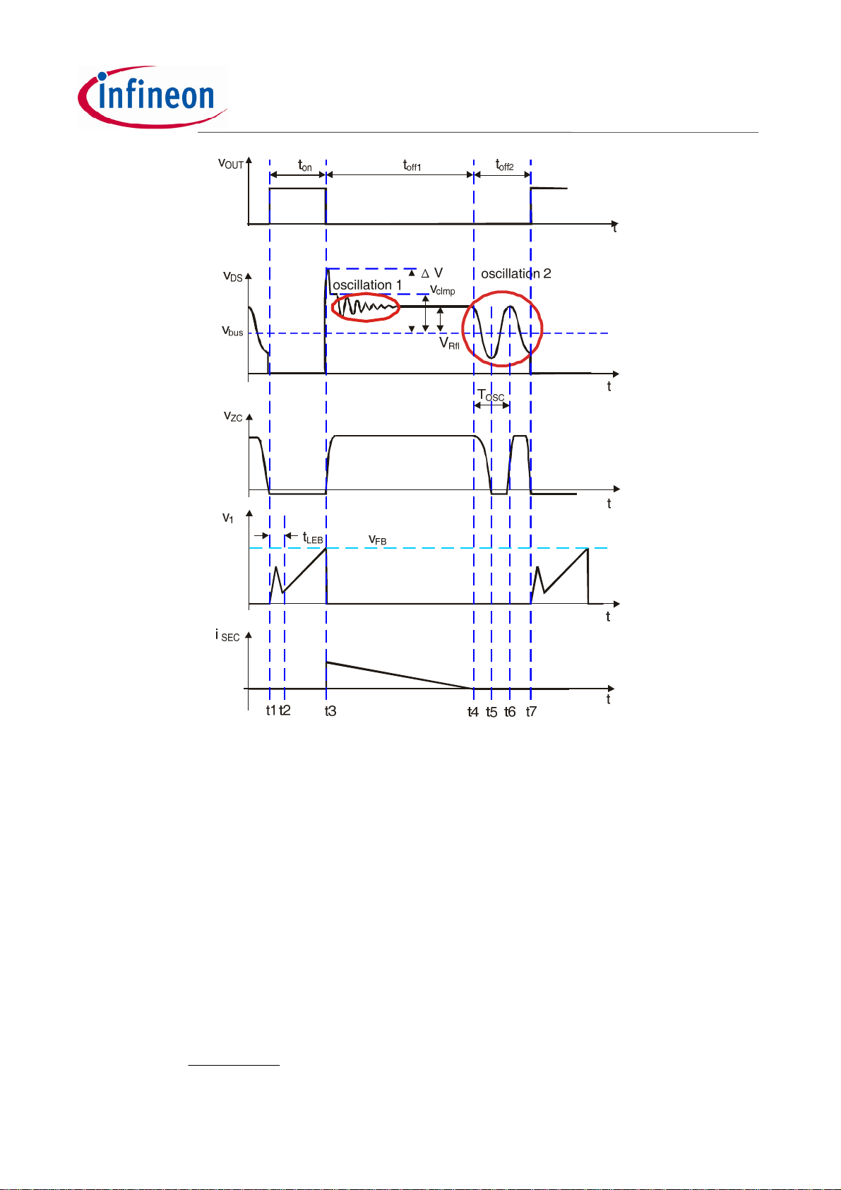
used for the flyback converter, the typical waveforms are shown in Figure 3. The voltage from the auxiliary
winding provides information about demagnetization of the power transformer, the information of input
voltage and output voltage.
is available. The transformer has one primary winding Wp, one or more secondary
bus
bus
As shown in Figure 3, after switch-on of the power switch the voltage across the shunt resistor VCSshows a
spike caused by the discharging of the drain-source capacitor. After the spike, the voltage VCSshows
information about the real current through the main inductance of the transformer Lp. Once the measured
current signal VCSexceeds the maximum value determined by the feedback voltage VFB, the power switch is
turned off. During this on-time, a negative voltage proportional to the input bus voltage is generated across
the auxiliary winding.
Design Guide 6 8 August 2011
Page 7
Quasi-resonant CoolSET design guide
ICE2QRxx65/80x
85 ~ 265 VAC
Dr1~D
r4
ZC
Power Management
W
C
bus
CZCR
ZC2
R
ZC1
VCC
Snubber
R
VCC
C
VCC
Startup Cell
D
VCC
Drain
p
W
a
D
O
W
s
C
O
C
PS
R
b1
L
f
V
C
O
f
PWM controller
CS
®
R
CS
Optocoupler
R
R
b2
ovs1
R
c1
FB
Cc1C
TL431
c2
R
ovs2
GND
Current Mode Control
Cycle-by-Cycle
current limitation
Zero Crossing Block
Active Burst Mode
Protections
Control Unit
CoolMOS
CoolSET®-Q1
Figure 2 Typical Application of ICE2QRxx65/80x
The drain-source voltage of the power switch Vdswill rise very fast after MOSFET is turned off. This is caused
by the energy stored in the leakage inductance of the transformer. A snubber circuit, RCD in most cases, can
be used to limit the maximum drain source voltage caused. After the oscillation 1, the drain-source voltage
goes to its steady value. Here, the voltage v
is the reflected value of the secondary voltage at the primary
Refl
side of the transformer and is calculated as:
VV
V
(1)
Refl
doout
n
where n the turns ratio of the transformer, which is defined in this document as:
/NNn
PS
(2)
with Npand Nsare the turns count of the primary and secondary winding, respectively.
After the oscillation 1 is damped, the drain-source voltage of the power switch shows a constant value of
V
bus+VRefl
t
off1
until the transformer is fully demagnetized. This duration builds up the first portion of the off-time
.
After the secondary side current falls to zero, the drains-source voltage of the power switch shows another
oscillation (oscillation 2 in Figure 3, this is also mentioned as the main oscillation in this document). This
oscillation happens in the circuit consisting of the equivalent main inductance of the transformer Lpand the
capacitor across the drain-source (or drain-ground) terminal CDSwhich includes C
of the MOSFET. The
o(er)
frequency of this oscillation is calculated as:
f
(3)
OSC2
The amplitude of this oscillation begins with a value of v
1
CL2π
DSP
and decreases exponentially with the elapsing
Refl
time, which is determined by the losses factor of the resonant circuit. The first minimum of the drain voltage
appears at the half of the oscillation period after the time t4and can be apporximated as:
V-VV
ReflbusdsMin
(4)
In the quasi-resonant control, the power switch is switched on at the minimum of the drain-source voltage.
From this kind of operation, the switching-on losses are minimized, and switching noise due to dVds/dt is
reduced compared to a normal hard-switching flyback converter.
Design Guide 7 8 August 2011
Page 8
Quasi-resonant CoolSET design guide
ICE2QRxx65/80x
Figure 3 Key waveforms of a quasi-resonant flyback converter
4 Functional description and component design
4.1 VCC Pre-Charging and Typical VCC Voltage During Start-up
In the CoolSET ICE2QRxx65/80xx, a startup cell is integrated to the CoolMOS. The startup cell provides a
pre-charging of the VCC capacitor till VCC voltage reaches the VCC turned-on threshold V
CoolSET begins to operate.
Once the mains input voltage is applied, a rectified voltage shows across the capacitor C
device provides a current to charge the VCC capacitor C
. Before the VCC voltage reaches a certain value,
vcc
. The high voltage
bus
the amplitude of the current through the high voltage device is only determined by its channel resistance and
can be as high as several mA. After the VCC voltage rises to certain level, the CoolSET controls the startup
cell so that a constant current around 1mA is provided to charge the VCC capacitor. It stops until the VCC
voltage exceeds the turned-on threshold V
. As shown in the time phase I of Figure 4, the VCC voltage
VCCon
increase almost linearly.
The time taken for the charging VCC to turn-on threshold can then be approximately calculated as:
CV
VCCVCCon
where I
t [5]
1
I
VCCcharge2
VCCcharge2
is the charging current from the startup cell which is 1.1mA, typically.
Design Guide 8 8 August 2011
VCCon
and the
Page 9

Figure 4 VCC voltage at start up
Quasi-resonant CoolSET design guide
ICE2QRxx65/80x
When the VCC voltage exceeds the turned-on threshold V
at time t1, the startup cell is switched off, and
VCCon
the CoolSET begins to operate with a soft-start. Because the energy from the auxiliary winding is not enough
to supply the CoolSET operation when output voltage is low, the VCC voltage drops (Phase II). Once the
output voltage is high enough, the VCC capacitor receives energy from the auxiliary winding from the time
point t2on. The VCC voltage will then reach a constant value depending on output load.
Precaution : For a typical application, start up should be VCC ramps up first, other pin (such as FB pin)
voltage will follow VCC voltage to ramp up. It is recommended not to have any voltage on other
pins (such as FBB; BBA and CS) before VCC ramps up.
4.1.1 VCC Capacitor
Since there is a VCC undervoltage protection, the capacitance of the VCC capacitor should be selected to be
high enough to ensure that enough energy is stored in the VCC capacitor so that the VCC voltage will never
touch the VCC under voltage protection threshold V
before the output voltage is built up. Therefore, the
VCCUVP
capacitance should fulfill the following requirement:
)t-(tI
12VCCop
V-V
VCCUVPVCCon
with I
C
[6]
VCC
the operating current of the CoolSET.
VCCop
4.2 Soft-Start
After CoolSET supply voltage is higher than 18V, which corresponding to t1 of Fig.4, CoolSET will start
switch with a soft start. The soft start function is built inside the CoolSET in a digital manner. During softstart,
the peak current of the MOSFET is controlled by an internal voltage reference instead of the voltage on FB
pin. The maximum voltage on CS pin for peak current control is increased step by step as shown in Figure 5.
The maximum duration of softstart is 12ms with 4ms for each step.
During softstart, the over load protection function is disabled.
Figure 5 Maximum current sense voltage during softstart
Design Guide 9 8 August 2011
Page 10

Quasi-resonant CoolSET design guide
FB
FBZL
FBZH
FBR1
FBR1
ICE2QRxx65/80x
4.3 Normal Operation
The PWM section of the CoolSET can be divided into two main portions: PWM controller for normal operation
and PWM controller for burst mode operation. The PWM controller for normal operation will be described in
the following paragraphs, while the PWM controller for burst mode operation will be discussed in the next
section.
The PWM controller for normal operation consists of digital signal processing circuit including an up/down
counter, a zero-crossing counter (ZC-counter) and a comparator, and analog circuit including a current
measurement unit and a comparator. The switch-on and -off time point is determined by the digital circuit and
the analog circuit, respectively. As input information for the switch-on determination, the zero-crossing input
signal and the value of the up/down counter are needed, while the feedback signal VFBand the current
sensing signal VCSare necessary for the switch-off determination. Details about the operation of the PWM
controller in normal operation are illustrated in the following paragraphs.
4.3.1 Switch-on Determination
As mentioned above, the digital signal processing circuit consists of an up/down counter, a zero-crossing
counter and a comparator. A ringing suppression time controller is implemented to avoid mistriggering by the
ring after MOSFET is turned off. Functionality of these parts is described as in the following.
4.3.1.1 Up/down Counter
The up/down counter stores the number of zero crossing to be detected to switch on the main power switch
after demagnetisation of the transformer. This value is a function of the feedback voltage, VFBwhich contains
information about the output power. Generally, a high output power results in a high feedback voltage, V
FB
According to this information, the value in the up/down counter is changed to a low value in case of high
feedback voltage, and to a high value in case of low feedback voltage. In ICE2QRxx65/80x, the lowest value
of the counter is 1 and the highest 7. Following text explains how the up/down counter value changes in
response to the feedback voltage VFB. The feedback voltage VFBis internally compared with three thresholds
V
FBZL
, V
FBZH
and V
. According to the results, the value in the up/down counter is changed, which is
FBR1
summarised in Table 1 and Figure 6 respectively.
According to the comparison results the up/down counter counts upwards, keeps unchanged or counts
downwards. However, the value in up/down counter is limited between 1 and 7. If the counter tends to count
beyond this range, the attempt is ignored.
In normal case, the up/down counter can only be changed by one each time at the clock period of 48ms.
However, to ensure a fast response to load increase, the counter is set to 1 in the following switching period
after the regulation feedback VFBexceeds the threshold V
V
Always lower than V
Once higher than V
, but always
FBZL
.
FBR1
Up/down counter action
Count upwards until 7
No changes
lower than V
Once higher than V
, but always
FBZH
Count downwards until 1
lower than V
Once higher than V
Counter set to 1
Table 1 Operation of the up/down counter
Design Guide 10 8 August 2011
Page 11

Quasi-resonant CoolSET design guide
clock T=48ms
ICE2QRxx65/80x
V
FB
V
FBR1
V
FBZH
V
FBZL
Up/down
counter
Case 1
Case 2
4 5 6 6 6 6 5 4 311
2 3 4 4 4 4 3 2 1
7 7 7 7 7 7 6 5 4
t
1
1Case 3
Figure 6 Up/down counter operation
4.3.1.2 Switch-on Determination
In the system, turn-on of the power switch depends on the value of the up/down counter, the value of the
zero-crossing counter and the voltage at the ZC pin VZC. Turn-on happens only when the value in the both
t
counters is the same and the voltage at the ZC is lower than the threshold V
values from both counters, a digital comparator is used. Once these counters have the same value, the
comparator generates a signal which sets the on/off flip-flop, only when the voltage VZCis lower than the
threshold V
Another signal which may trigger the digital comparator is the output of a T
ZCCT
.
sMax
maximum off time to avoid the low-frequency operation.
During active burst mode operation, the digital comparator is disabled and no pulse will be generated.
. For comparison of the
ZCCT
clock signal, which limits the
4.3.2 Switch-off Determination
In the converter system, the primary current is sensed by an external shunt resistor, which is connected
between Current Sense pin and the common ground. The sensed voltage across the shunt resistor VCSis
applied to an internal current measurement unit, and its output voltage V1is compared with the feedback
voltage VFB. Once the voltage V1exceeds the voltage VFB, the output flip-flop is reset. As a result, the main
power switch is switched off. The relationship between the V1and the VCSis described by:
where G
PWM
=3.3, V
G VVV
PWM
=0.7
CS1
PWMPWM
[7]
To avoid mistriggering caused by the voltage spike across the shunt resistor after switch-on of the main
power switch, a 330ns leading edge blanking time (t
) is applied to the output of the comparator.
LEB
4.4 Active Burst Mode Operation
At very low load condition, the CoolSET enters active burst mode operation to minimize the input power.
Details about active burst mode operation are explained in the following paragraphs.
4.4.1 Entering Active Burst Mode Operation
For determination of entering active burst mode operation, three conditions apply:
Design Guide 11 8 August 2011
Page 12

Quasi-resonant CoolSET design guide
ICE2QRxx65/80x
The feedback voltage is lower than the threshold of VEB(1.25V). Accordingly, the peak voltage
across the shunt resistor is 0.17V;
The up/down counter has its maximal value of 7;
The two above conditions have to been fulfilled for a certain blanking time duration t
BEB
(30ms)
Once all of these conditions are fulfilled, the active burst mode flip-flop is set and the CoolSET enters burst
mode operation and the gate will be turned off until VFBincrease to on threshold VBH. The total blanking time
to enter the active burst mode depends on the up counting time and the 30ms extra blanking time.
msmsvaluecounterT
ingtotalblank
3048_7
For example. If before the load change, current up/down counter value is 3, then the total blanking time will
be:
(7-3) x 48ms + 30ms = 222ms.
This multi-conditional determination for entering active burst mode operation prevents mistriggering of
entering active burst mode operation, so that the CoolSET enters active burst mode operation only when the
output power is really low during the preset blanking time.
4.4.2 During Burst Mode Operation
After entering the Active Burst Mode the feedback voltage rises as VOstarts to decrease due to the inactive
PWM section. One comparator observes the feedback signal if the voltage level VBH(3.6V) is exceeded. In
that case the internal circuit is again activated by the internal bias to start with switching.
Turn-on of the power MOSFET is triggered by the timer. The PWM generator for burst mode operation
composes of a timer with a fixed frequency of 52 kHz, typically, and an analog comparator. Turn-off is
resulted by comparison of the voltage signal V1with an internal threshold, by which the voltage across the
shunt resistor V
which sets the maximal duty ratio to 50%. In operation, the output flip-flop will be reset by one of these
signals which come first.
is 0.34V, accordingly. A turn-off can also be triggered by the maximal duty ratio CoolSET
csB
V
V
V
V
V
FB
V
FBLB
FBBOn
FBBOff
V
FBEB
V
1.0V
CSB
V
VCCoff
V
blanking Window (t
CS
Current limit level
during Active Burst
Mode
VCC
O
Entering
Active Burst
Mode
time to 7thzero and
Max. Ripple < 1%
BEB
)
Leaving
Active Burst
Mode
t
t
t
t
Figure 7 Signals in active burst mode
Design Guide 12 8 August 2011
Page 13

Quasi-resonant CoolSET design guide
ICE2QRxx65/80x
If the output load is still low, the feedback signal decreases as the PWM section is operating. When feedback
signal reaches the low threshold VBL(3.0V), the internal bias is reset again and the PWM section is disabled
until next time regultaion signal increases beyond the VBHthreshold. During the active burst mode the
feedback signal is changing like a saw tooth between 3.0V and 3.6V shown in Figure 7.
4.4.3 Leaving Active Burst Mode
The feedback voltage immediately increases if there is a high load jump. This is observed by one comparator.
As the current limit is 34% during active burst mode a certain load is needed so that feedback voltage can
exceed VLB (4.5V). After leaving active burst mode, maximum current can now be provided to stabilize VO. In
addition, the up/down counter will be set to 1 immediately after leaving active burst mode. This is helpful to
decrease the output voltage undershoot.
4.5 Current sense
The PWM comparator inside the CoolSET has two inputs: one from current sense pin and the other from
feedback voltage. Before being sent to the PWM comparator, there is an offset and operational gain on
current sense voltage. In normal operation, the relationship between feedback voltage and maximum current
sense voltage is determined by equation (8).
where G
=3.3 and V
PWM
PWM
CSPWMFB
=0.7
VVGV
PWM
pk
_
(8)
The absolute maximum current sense voltage, V
is 1V. Therefore, the current sense resistor can be
CS_PK
chosen according to the maximum required peak current in the transformer as shown in (9).
IR
/1
ppkCS
_
(9)
The design procedure of quasi-resonant flyback transformer is shown in [2]. In addition, a leading edge
blanking (LEB) is already built inside the current sense pin. The typical value of leading edge blanking time is
330ns, which can be thought as a minimum on time.
4.6 Feedback
Inside the CoolSET, the feedback (FB) pin is connected to the 5V voltage source through a pull-up resistor
RFB. Outside the CoolSET, this pin is connected to the collector of opto-coupler. Normally, a ceramic
capacitor CFB, 1nF for example, can be put between this pin and ground for smooting the signal.
Feedback voltage will be used for a few functions as following:
It determines the maximum current sense voltage, equivalent to the transformer peak current.
It determines the ZC counter value according to load condition
4.7 Zero crossing
The circuit components connected to zero crossing (ZC) pin include resistors R
CZC. The values of three components shall be chosen so that the three functions combined to this pin will
perform as designed.
ZC1
and R
and capacitor
ZC2
At first, the ratio between R
Assuming the protection level of output voltage is V
ZC1
and R
is chosen first to set the trigger level of output overvoltage protection.
ZC2
, the turns of auxiliary winding is Na and the turns of
O_OVP
secondary output winding is Ns, the ratio is calculated as
N
S
NV
aO
(10)
In (10), V
R
ZC
2
RR
is the trigger level of output overvoltage protection which can be found in product datasheet.
ZCOVP
V
ZCZC
ZCOVP
21
Design Guide 13 8 August 2011
Page 14

Quasi-resonant CoolSET design guide
ICE2QRxx65/80x
Secondly, as shown in Figure 3, there are two delay times for detection of the zero crossing and turn on of
the MOSFET. The delay time t
voltage follows below 100mV. This delay time can be adjusted through changing CZC. The second one, t
is the delay time from ZC voltage follows below 100mV to the MOSFET is turned on. This second delay time
is determined by CoolSET internal circuit and cannot be changed. Therefore, the capacitance CZCis chosen
to adjust the delay time t
Delay1
normally done through experiment.
Next, there is a foldback point correction integrated in this pin. This function is to decrease the peak current
limit on current sense pin so that the maximum output power of the converter will not increase when the input
voltage increases. This is done through sensing the current flowing out from ZC pin when MOSFET is turned
on.
When the main power switch is turned on, the negative voltage on auxiliary winding can be calculated as
N
VV (11)
BUSaux
N
Inside ZC pin, there is a clamping circuit so that the ZC pin voltage is kept at nearly zero. Therefore, the
current flowing out from ZC pin at this moment is
I
(12)
ONZC
_
NV
NR
1
is the delay from the drain-source voltage cross the bus voltage to the ZC
Delay1
Delay2
MOSFET is justed turned on at the valley point of drain-source voltage. This is
a
P
aBUS
PZC
,
The threshold in ZC pin to start the foldback point correction is IZC= 0.5 mA. Therefore, R
can be chosen
ZC1
so that
NV
aSBUS
_
NmA
*5.0
P
In (13), V
R
(13)
ZC
1
is the voltage from which the maximum output power is desired to be maintained at constant
BUS_S
level. The corresponding maximum current sense voltage in relation to the ZC current is shown in Figure 8.
1
0.9
0.8
Vcs-max(V)
0.7
0.6
300 500 700 900 1100 1300 1500 1700 1900 2100
Izc(uA)
Figure 8 Maximum current sense limit versus ZC current during MOSFET on-state
In addition, as shown in Figure 3, an overshoot is possible on ZC voltages when MOSFET is turned off. This
is because of the oscillation 1 on drain voltage, shown in Figure 3 may be coupled to the auxiliary winding.
Therefore, the capacitance CZCand ratio can be adjusted to obtain the trade off between the output
overvoltage protection accuracy and the valley switching performace.
If, however, the amplitude of the ring at the ZC pin is too small and the zero crossing cannot be detected, it is
advised to increase the Drian_Source capacitor, CDSof the MOSFET. But this capacitor would incur switching
loss, the value is suggested to be as small as possible; best to be <100pF.
Furthermore, to avoid mis-triggerring of ZC detection just after MOSFET is turned off, a ring suppression time
is provided. The ring suppression time is 2.5 μs typically if VZC is higher than 0.7V and it is 25 μs typically if
Design Guide 14 8 August 2011
Page 15

Quasi-resonant CoolSET design guide
ICE2QRxx65/80x
VZCis lower than 0.7V. During the ring suppression time, CoolSET can not be turned on again. Therefore, the
ring suppression time can also be thought as a minimum off time.
4.8 Protections
The ICE2QRxx65/80x CoolSET provides full protection functions. The following table summarizes these
protection functions.
VCC Overvoltage Auto Restart Mode
VCC Undervoltage Auto Restart Mode
Overload/Open Loop Auto Restart Mode
Over Temperature Auto Restart Mode
Output Overvoltage Latched Off Mode
Short Winding Latched Off Mode
During Operation, the VCC over voltage is continuously monitored. In case of an under- or an over-voltage,
the CoolSET is reset and the main power switch is then kept off. After the VCC voltage falls below the
threshold V
exceeds the threshold V
In case of open control loop or output over load, the feedback voltage will be pulled up. After a blanking time
of 24ms, the CoolSET enters auto-restart mode. The blanking time here enables the converter to provide a
high power in case the increase in VFBis due to a sudden load increase.
, the startup cell is activated. The VCC capacitor is then charged up. Once the voltage
VCCoff
, the CoolSET begins to operate with a new soft-start.
VCCon
During off-time of the power switch, the voltage at the zero-crossing pin is monitored for output over-voltage
detection. If the voltage is higher than the preset threshold V
blanking time.
If the junction temperature of CoolSET exceeds 140oC, the CoolSET enters into auto-restart mode.
If the voltage at the current sensing pin is higher than the preset threshold V
switch, the CoolSET is latched off. This is short-winding protection.
During latch-off protection mode, when the VCC voltage drops to 10.5V, the startup cell is activated and the
VCC voltage is charged to 18V then the startup cell is hut down again and repeats the previous procedure.
The latch-off mode can only be reset if the VCC voltage < 6.23V.
, the CoolSET is latched off after the preset
ZCOVP
during on-time of the power
CSSW
4.9 Others
For quasi-resonant flyback converters, it is possible that the operation frequency goes too low, which
normally resulted in audible noise. To prevent it, in ICE2QRxx65/80x, a maximum on time and maximum
switching period is provided.
The maximum on time in ICE2QRxx65/80x is 30 μs typically. If the gate is maintained ON for 30 μs, CoolSET
will turn off the gate regardless of the current sense voltage.
When the MOSFET is off and CoolSET can not detect enough number of ZC to turn on the MOSFET,
CoolSET will turn on the MOSFET when the maximum switching period, 50 μs typically, is reached. Please
note that even a non-zero ZC pin voltage can not prevent CoolSET from turning on the MOSFET. Therefore,
during soft start, a CCM operation of the converter is expected.
5 Typical application circuit
A 12W evaluation board with ICE2QR4780z is shown below as an example. The detailed information can be
found in [5]. The application circuit is shown in Figure 9.
Design Guide 15 8 August 2011
Page 16

Quasi-resonant CoolSET design guide
ICE2QRxx65/80x
Figure 9 Schematic of the 12W 5V evalulation board with ICE2QR4780Z
6 Input Power Curves for Quasi Coolset 650V/800V
The purpose of the input power curve is to simplify the selection of the CoolSET®device. The curve is a
function of ambient temperature to the input power of the system in which the input filter loss, bridge rectifier
loss and the MOSFET power loss are considered. The only information needed is the required output power,
the input voltage range, the operating ambient temperature and the efficiency of the system. The required
input power can then be calculated as equation (14).
P
P (14)
where Pin: input power, P
It then simply looks up the closed input power at the required ambient temperature from the input power
curve.
The input power curves for the Quasi Resonant CoolSET family are listed below.
o
in
: output power, η : efficiency
o
ICE2QR0665: Vin=85Vac~265Vac ICE2QR0665: Vin=230Vac±15%
Figure 10 Input power curve for ICE2QR0665
Design Guide 16 8 August 2011
Page 17

ICE2QR1765: Vin=85Vac~265Vac ICE2QR1765: Vin=230Vac±15%
Figure 11 Input power curve for ICE2QR1765
Quasi-resonant CoolSET design guide
ICE2QRxx65/80x
ICE2QR4765: Vin=85Vac~265Vac ICE2QR4765: Vin=230Vac±15%
Figure 12 Input power curve for ICE2QR4765
ICE2QR0665Z: Vin=85Vac~265Vac ICE2QR0665Z: Vin=230Vac±15%
Figure 13 Input power curve for ICE2QR0665Z
Design Guide 17 8 August 2011
Page 18

ICE2QR1065Z: Vin=85Vac~265Vac ICE2QR1065Z: Vin=230Vac±15%
Figure 14 Input power curve for ICE2QR1065Z
Quasi-resonant CoolSET design guide
ICE2QRxx65/80x
ICE2QR1765Z: Vin=85Vac~265Vac ICE2QR175Z: Vin=230Vac±15%
Figure 15 Input power curve for ICE2QR1765Z
ICE2QR4765Z: Vin=85Vac~265Vac ICE2QR4765Z: Vin=230Vac±15%
Figure 16 Input power curve for ICE2QR4765Z
Design Guide 18 8 August 2011
Page 19

ICE2QR0665G: Vin=85Vac~265Vac ICE2QR0665G: Vin=230Vac±15%
Figure 17 Input power curve for ICE2QR0665G
Quasi-resonant CoolSET design guide
ICE2QRxx65/80x
ICE2QR1765G: Vin=85Vac~265Vac ICE2QR1765G: Vin=230Vac±15%
Figure 18 Input power curve for ICE2QR1765G
ICE2QR4765G: Vin=85Vac~265Vac ICE2QR4765G: Vin=230Vac±15%
Figure 19 Input power curve for ICE2QR4765G
Design Guide 19 8 August 2011
Page 20

ICE2QR0680Z: Vin=85Vac~265Vac ICE2QR0680Z: Vin=230Vac±15%
Figure 20 Input power curve for ICE2QR0680Z
Quasi-resonant CoolSET design guide
ICE2QRxx65/80x
ICE2QR2280Z: Vin=85Vac~265Vac ICE2QR2280Z: Vin=230Vac±15%
Figure 21 Input power curve for ICE2QR2280Z
ICE2QR4780Z: Vin=85Vac~265Vac ICE2QR4780Z: Vin=230Vac±15%
Figure 22 Input power curve for ICE2QR4780Z
Design Guide 20 8 August 2011
Page 21

Quasi-resonant CoolSET design guide
ICE2QRxx65/80x
ICE2QR2280G: Vin=85Vac~265Vac ICE2QR2280G: Vin=230Vac±15%
Figure 23 Input power curve for ICE2QR2280G
The major assumption for the calculation is listed below.
1. Reflection voltage from secondary side to primary side is 115V for 650V CoolSET and 150V for 800V
CoolSET.
2. The assumed maximum power for the device is when the junction temperature of the integrated
CoolMOS®reaches 125°C. (With some margins to reach the over temperature protection of the
device : 130°C). The maximum R
3. For 650V DIP-8 CoolSET there is no copper area as heatsink and the R
CoolSET there is no copper area as heatsink and the R
is no copper area as heatsink and the R
copper area of 2oz PCB at drain pin for heatsink and the R
there is 232mm2copper area of 2oz PCB at drain pin for heatsink and the R
4. Saturation current (I
@ 125°C) of the MOSFET is considered which is showed in below table.
d_max
5. The typical resistance of the EMI filter is listed in the below table.
of the device at 125°C is taken for calculation.
dson
=96K/W, for 650V DSO-12 CoolSET there
thja
=110K/W , for 800V DIP-7 CoolSET there is 232mm
thja
=80K/W and for 800V DSO12 CoolSET
thja
=90K/W, for 650V DIP-7
thja
=85K/W.
thja
2
6. The voltage drop for the bridge rectifier is assumed to be 1V.
Rdson_125°C (Ω) I
@125°C (A) R
d_max
EMI_filter
(Ω) V
ICE2QR0665x 1.58 9.95 2 * 0.56 2 * 1
ICE2QR1065x 2.22 6.47 2 * 0.56 2 * 1
ICE2QR1765x 4.12 4.03 2 * 1 2 * 1
ICE2QR4765x 12.5 1.67 2 * 3 2 * 1
ICE2QR0680x 1.58 12.60 2 * 0.56 2 * 1
ICE2QR2280x 5.80 2.87 2 * 2 2 * 1
ICE2QR4780x 11.50 1.45 2 * 3 2 * 1
F_bridge
(V)
Design Guide 21 8 August 2011
Page 22

Quasi-resonant CoolSET design guide
ICE2QRxx65/80x
7 PCB Layout Recommendation
In power supply system, PCB layout is a key point for a successful design. Following are some suggestions
for this (refer to application circuit in Figure 9).
Minimize the loop with pulse share current or voltage; examples are the loop formed by the bus
voltage source, primary winding, main switch and current sensing resistor or the loop consisting of
secondary winding, output diode and output capacitor, or the loop of VCC power supply.
Good grounding of the CoolSET; as the CoolSET sees every signal to the reference point of the
CoolSET ground which is also the ground of the VCC power supply, it is advisable that the ground of
the CoolSET is connected to the bus voltage ground through a short and thick PCB track in a star
structure. Note that ground of CoolSET is treated as small signal ground and the RCSresistor ground
and primary ground of auxiliary winding of the transformer are treasted as power loop ground. It
needs to be separated before connected to the bulk capacitor ground.
Good grounding of other parts/functions. This includes the CoolSET ground, FB loop ground, ZC loop
ground and the VCC loop ground. It is advisable that all the above grounds connected to the
CoolSET ground and then connected to the bus voltage ground using a star-structure.
Power loop grounds can connect to bulk capacitor ground directly and separately; such as EMI filter
return ground Y capacitor, C15, auxiliary winding ground of transformer and the RCSresistor.
The high voltage pins are connected to bus voltage in typical applications. During lightning surge test,
the noise on bus voltage is high. It is suggested that the track to high voltage pin shall be kept away
from other small signal tracks. The distance is better to be more than 3mm.
8 Product Portfolio Quasi Resonant CoolSET
Type Package MOSFET R
V
DS
ICE2QR0665 DIP-8 650V
ICE2QR1765 DIP-8 650V
ICE2QR4765 DIP-8 650V
ICE2QR0665Z DIP-7 650V
ICE2QR1065Z DIP-7 650V
ICE2QR1765Z DIP-7 650V
ICE2QR4765Z DIP-7 650V
ICE2QR0665G DSO-12 650V
ICE2QR1765G DSO-12 650V
ICE2QR4765G DSO-12 650V
3
3
3
3
3
3
3
5
3
3
ICE2QR0680Z DIP-7 800V 0.65 Ω 102W
ICE2QR2280Z DIP-7 800V 2.2 Ω 53W
ICE2QR4780Z DIP-7 800V 4.7 Ω 39W
ICE2QR2280G DSO-12 800V 2.2 Ω 51W
1
DSon
Input power Input power Features
230 V
0.65 Ω 88W
1.7 Ω 56W
4.7 Ω 30W
0.65 Ω 79W
0.92Ω 71.6W
1.7 Ω 54.8W
4.7 Ω 31W
0.65 Ω 79W
1.7 Ω 49W
4.7 Ω 29W
AC
4
4
4
4
4
4
4
6
4
4
7
5
5
5
®
(85-265) V
50W
33W
19W
45W
41.0W
30.6W
18W
45W
28W
17W
57W
30W
22W
30W
2
AC
4
4
4
4
4
4
4
4
4
4
5
5
5
5
DFR, PPL
DFR, PPL
DFR, PPL
DFR, PPL
DFR, PPL
DFR, PPL
DFR, PPL
DFR, PPL
DFR, PPL
DFR, PPL
DFR, PPL, 800V
DFR, PPL, 800V
DFR, PPL, 800V
DFR, PPL, 800V
1
Typical value @ Tj=25°C
2
DFR=Digital Frequency Reduction; PPL= Peak Power Limitation
3
Tj=110°C
4
Calculated maximum input power in an open frame design at Ta=50°C, Tj=125°C and without copper area heat sink.
5
Tj=110°C
6
Calculated maximum input power in an open frame design at Ta=50°C, Tj=125°C and without copper area heat sink.
7
Calculated maximum input power in an open frame design at Ta=50°C, Tj=125°C and with 232mm22 oz copper area heat sink.
Design Guide 22 8 August 2011
Page 23

Quasi-resonant CoolSET design guide
o
(er)
n
startup
VCC
out_OVP
BUS_S
sw
_bb
s
B
ICE2QRxx65/80x
9 Design Equations
With reference to the typical application diagram in Figure 2, some useful design equations are tabulated as
below (refer to symbols to datasheet):
Transformer Calculation (Quasi Resonant flyback)
Input data
Turn ratio
Primary Inductance
Primary peak current
Primary turns
Secondary turns
Vin_min=85Vdc, Vin_max=400Vdc,
Vdc_max=515V for 650V MOSFET, 550V for 800V MOSFET
VV
inds
n
L
p
f
= switching frequency at low line full load; suggested : 40~65kHz
sw_LF
CDS= capacitance across Drain_Source of MOSFET (including C
I
Ppk
N
N
_
p
s
N
p
max_max_
VV
diodeout
1
11
min_
P
out
5.0
IL
max_
pp
AB
minmax
VnV
outin
fL
LFswp
_
Pf
_
outLFsw
5.0
_
of MOSFET)
2
Cf
DSLFsw
VV
Auxiliary turns
N
aux
diodecc
VV
diodeout
ICE2QRxx65/80x external component design
V
Current sense resistor
VCC capacitor
ZC resistors
ZC Capacitor
Enter burst mode
power
Leave burst mode
power
R_
CS
C
VCC
t
R
ZC
V
t
delay
current drops to 0A (refer to Figure 3)
f
f
= switching frequency at burst mode
CSth
I
Ppk
It
V
= startup time of system; suggested C
1
= output OVP voltage; V
can be taken as 100ns; f
_
= switching frequency before entering burst mode
_
VCCon
NV
_
5.0
2tan
auxSBUS
NmA
1
4
LP
5.0
LP
5.0
N
s
eVCCchstartup
2arg
is ≥ 22μF
R
1
;
p
PenterBurst
PleaveBurst
R
2
ZC
N
aux
N
s
=bulk capacitor voltage to maintain max. output power
ftC
= measured Drain oscillation frequency after secondary side
osc2
V
CSB
R
CS
2
oscdelayZC
VV
PWMFBEB
GR
PWMCS
2
f
sB
ZC
VV
_
V
RR
2
f
ZCOVP
21
ZCZC
bbsw
_
diodeOVPout
1
1
2
fRR
221
oscZCZC
Please refer to the below references for some more useful calculation formulas.
Design Guide 23 8 August 2011
Page 24

Quasi-resonant CoolSET design guide
ICE2QRxx65/80x
10 References
[1] Design tips for flyback converters using the Quasi-Resonant PWM controller ICE2QS01, Infineon
Technologies, 2006. [ANPS0005]
[2] Converter design using the quasi-resonant PWM controller ICE2QS01, application notes, Infineon
Technologies, 2006. [ANPS0003]
[3] Determine the switching frequency of Quasi-Resonant flyback converters designed with ICE2QS01,
Infineon Technologies, 2006. [ANPS0004]
[4] 12W 5V Evaluation Board with Quasi-Resonant PWM controller ICE2QR4780Z, Application notes,
Infineon technologies 2011.
[5] 12W 5V Evaluation Board with Quasi-Resonant PWM controller ICE2QR4765, Application notes,
Infineon technologies 2010.
[6] 20V 40W Evaluation Board with Quasi-Resonant PWM controller ICE2QR0665, Application notes,
Infineon technologies 2009.
[7] 20W 5V Evaluation Board with Quasi-Resonant PWM controller ICE2QR2280G, Application notes,
Infineon technologies 2011.
[8] 36W 12V Evaluation Board with Quasi-Resonant PWM Controller ICE2QS03G, AN-EVALQRS-
ICE2QS03G, Infineon Technologies, 2009
[9] Datasheet, ICE2QR0665, “Off-Line SMPS Quasi-Resonant PWM Controller with integrated 650V
Startup Cell/Depletion CoolMOS®In DIP8”, Infineon Technologies
[10] Datasheet, ICE2QR1765, “Off-Line SMPS Quasi-Resonant PWM Controller with integrated 650V
Startup Cell/Depletion CoolMOS®In DIP8”, Infineon Technologies
[11] Datasheet, ICE2QR4765, “Off-Line SMPS Quasi-Resonant PWM Controller with integrated 650V
Startup Cell/Depletion CoolMOS®In DIP8”, Infineon Technologies
[12] Datasheet, ICE2QR0680Z, “Off-Line SMPS Quasi-Resonant PWM Controller with integrated 800V
Startup Cell/Depletion CoolMOS®In DIP7”, Infineon Technologies
[13] Datasheet, ICE2QR2280Z, “Off-Line SMPS Quasi-Resonant PWM Controller with integrated 800V
Startup Cell/Depletion CoolMOS®In DIP7”, Infineon Technologies
[14] Datasheet, ICE2QR4780Z, “Off-Line SMPS Quasi-Resonant PWM Controller with integrated 800V
Startup Cell/Depletion CoolMOS®In DIP7”, Infineon Technologies
[15] Datasheet, ICE2QR0665Z, “Off-Line SMPS Quasi-Resonant PWM Controller with integrated 650V
Startup Cell/Depletion CoolMOS®In DIP7”, Infineon Technologies
[16] Datasheet, ICE2QR1065Z, “Off-Line SMPS Quasi-Resonant PWM Controller with integrated 650V
Startup Cell/Depletion CoolMOS®In DIP7”, Infineon Technologies
[17] Datasheet, ICE2QR1765Z, “Off-Line SMPS Quasi-Resonant PWM Controller with integrated 650V
Startup Cell/Depletion CoolMOS®In DIP7”, Infineon Technologies
[18] Datasheet, ICE2QR4765Z, “Off-Line SMPS Quasi-Resonant PWM Controller with integrated 650V
Startup Cell/Depletion CoolMOS®In DIP7”, Infineon Technologies
[19] Datasheet, ICE2QR0665G, “Off-Line SMPS Quasi-Resonant PWM Controller with integrated 650V
Startup Cell/Depletion CoolMOS®In DSO12”, Infineon Technologies
[20] Datasheet, ICE2QR1765G, “Off-Line SMPS Quasi-Resonant PWM Controller with integrated 650V
Startup Cell/Depletion CoolMOS®In DSO12”, Infineon Technologies
[21] Datasheet, ICE2QR4765G, “Off-Line SMPS Quasi-Resonant PWM Controller with integrated 650V
Startup Cell/Depletion CoolMOS®In DSO12”, Infineon Technologies
[22] Datasheet, ICE2QR2280G, “Off-Line SMPS Quasi-Resonant PWM Controller with integrated 800V
Startup Cell/Depletion CoolMOS®In DSO12”, Infineon Technologies
Design Guide 24 8 August 2011
 Loading...