

Page 1

UM_201709_PL21_011
COOLDIM_PRG_BOARD
User manual for CDM10V programming board
About this document
Scope and purpose
CDM10V programming user manual describes the “COOLDIM_PRG_BOARD” burner board usage, the UART
protocol handling and the fusing details.
Intended audience
CDM10V programming board user.
Table of contents
About this document ....................................................................................................................... 1
Table of contents ............................................................................................................................ 1
1 CDM10V BURNER .................................................................................................................... 2
1.1 Introduction ............................................................................................................................................. 2
1.2 Chip orientation ...................................................................................................................................... 2
1.3 Control buttons ....................................................................................................................................... 3
1.4 Switches ................................................................................................................................................... 3
1.5 Connectors / Jumper .............................................................................................................................. 4
2 Fusing details ........................................................................................................................ 5
2.1 UART configuration ................................................................................................................................. 5
2.2 Fusing conditions .................................................................................................................................... 5
2.3 Fusing procedure .................................................................................................................................... 6
Revision history ............................................................................................................................. 8
User Manual Please read the Important Notice and Warnings at the end of this document V 1.0
www.infineon.com page 1 of 9 2017-09-19
Page 2
COOLDIM_PRG_BOARD
User manual for CDM10V programming board
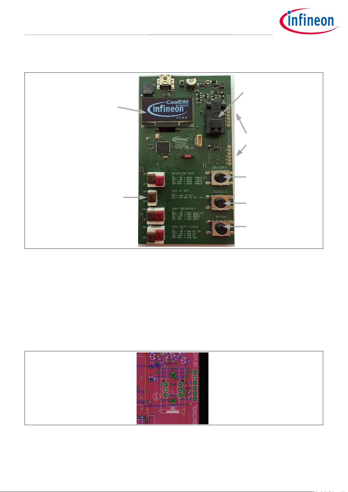
CDM10V BURNER
Display
Socket
7 DIP switsches
fuse settings
Power
ON/OFF
Toggle
Display
view
Burn
button
Connectors
1 CDM10V BURNER
Figure 1 CDM10V BURNER
1.1 Introduction
The COOLDIM_PRG_BOARD is used to set fuses inside CDM10V chip. It is supplied from a USB power supply
(5 V / 1 A) or could also be connected to a USB port of the PC. User will be guided through the burning process
by the microcontroller firmware. If an error occur during handling user will be advised by firmware how to
proceed. When no button is pressed during 5 minutes the display is switched off automatically and the LED
below the display is flashing once per second, pressing any button will switch on the display again.
1.2 Chip orientation
Figure 2 Chip orientation
Pin “1” of the chip shall be located in the lower left corner of the open socket. This is marked with a “1” on the
PCB.
User Manual 2 of 9 V 1.0
2017-09-19
Page 3
COOLDIM_PRG_BOARD
User manual for CDM10V programming board
CDM10V BURNER
Dimmer / resistor
bias
00
200 µA
DEFAULT
01
100 µA
10
50 µA
11
500 µA
Dim-to-off
0
NOT ENABLED
DEFAULT
1
ENABLE DIM-TO-OFF
PWM frequency
00
1000 Hz
DEFAULT
01
500 Hz
10
200 Hz
11
2000 HZ
Minimum duty cycle
00
5%
DEFAULT
01
2% 10
1% 11
10%
1.3 Control buttons
ON/OFF
Check if chip is applied in correct position and turn supply voltage on or off. When supply is turned on all 4
parameters are measured and shown in display. If one parameter could not be measured a contact fail is
expected supply is turned off and the user is informed to check the socket. If none of the parameter could be
measured user is informed that it is expected that socket is empty and supply is turned off. Only if all
parameter could be measured correctly (+/- 10%) supply stays on and allows the use to proceed.
Toggle
Toggle screen to show either chip settings or board settings. To burn the board settings user has to switch to
board settings view.
Burn
Start the fuse burning procedure. Fuse burning will only be started if:
1. The board settings differ from chip settings
2. Setting one (or several) bit to “1”
If these conditions are not fulfilled, burn procedure is aborted.
1.4 Switches
The switches are used to set the state of the fuses. Please note: user is only able to set a fuse bit from “0” to “1”.
If a bit is already set to “1” it could be not reversed and burn fuse will be aborted. The decoding of the switches
is printed on the board and will be shown in board settings view on the display.
Table 1 CDM10V settings
User Manual 3 of 9 V 1.0
2017-09-19
Page 4

COOLDIM_PRG_BOARD
User manual for CDM10V programming board
CDM10V BURNER
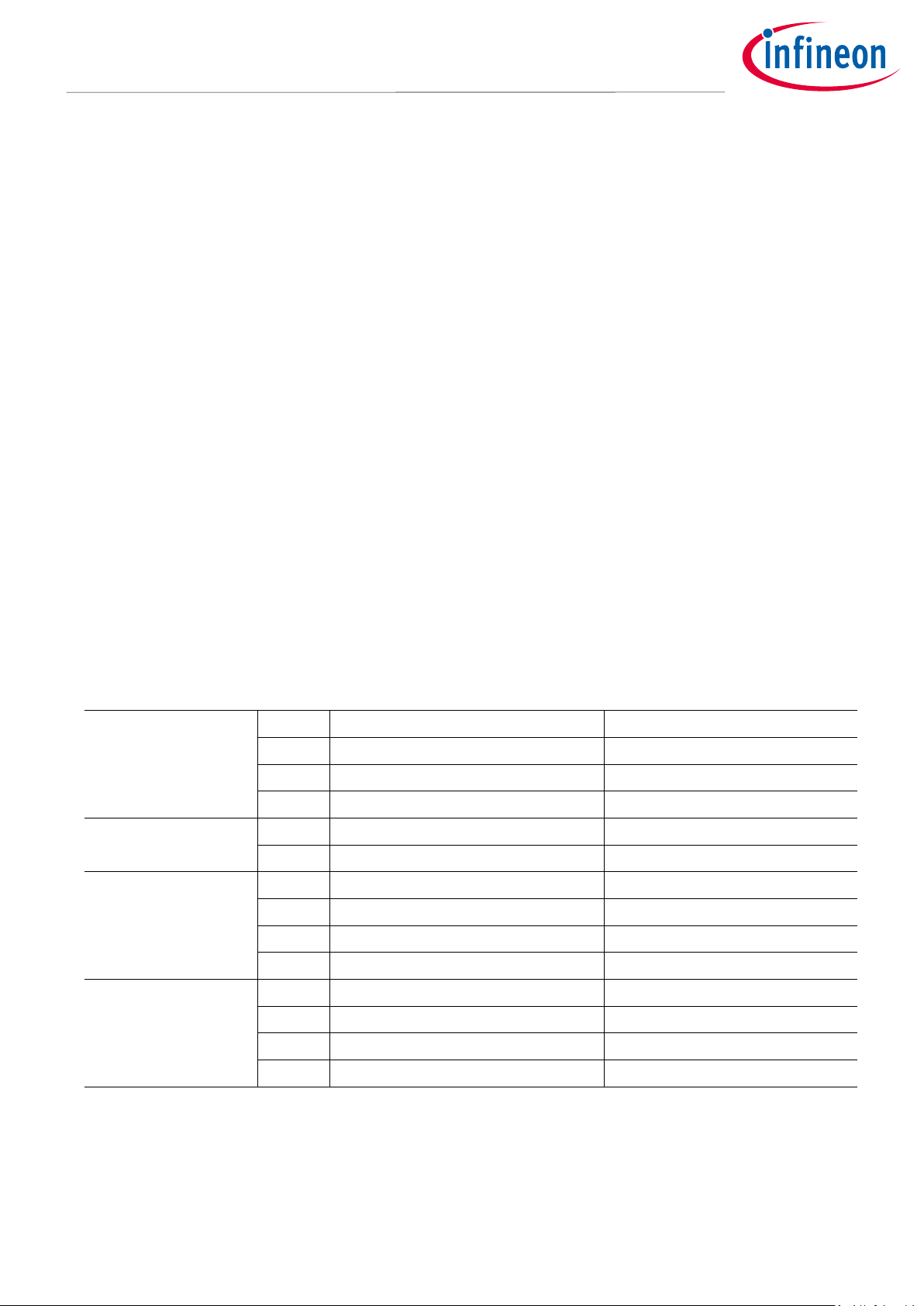
1.5 Connectors / Jumper
Optional connectors for external socket board.
Figure 3 Connectors
User Manual 4 of 9 V 1.0
2017-09-19
Page 5

COOLDIM_PRG_BOARD
User manual for CDM10V programming board
Fusing details
Resistor
Bias
Dim-
to-
OFF
PWM
frequency
PWM
min. duty
cycle
Startbit
Stopbit
D1 D2
0 0 : 200 µA
0 1 : 100 µA
1 0 : 50 µA
1 1 : 500 µA
CMD
D0 D1 D2 D3 D4 D5 D6 D7
D4 D5
0 0 : 1 kHz
0 1 : 500 Hz
1 0 : 200 Hz
1 1 : 2kHz
D6 D7
0 0 : 5 %
0 1 : 2 %
1 0 : 1 %
1 1 : 10 %
VFss
UART
interface
RxD
Vcc
6
5
4
1
2
3
Dimming
IC
Iout
Condition
Nom. value
Limits
Vcc
11.0 V
V
Fss
4.1 V
+-0.1 V
I
Fss
20 mA
Temperature
25°C
2 Fusing details
2.1 UART configuration
The serial port (9600 Baud, 1 stop bit, no parity) enables a onetime reconfiguration of parameters for device
function. The reserved CMD bit has to be set to HIGH. After this bit the 7 programming has to be sent in the
order shown in the picture below.
Figure 4 UART data frame format
The figure below shows the minimal fuse programming circuit diagram. The LED is optional and can be used to
signalize the correct fusing procedure.
Figure 5 FUSE programming minimal circuit
2.2 Fusing conditions
Table 2 Fusing conditions
User Manual 5 of 9 V 1.0
2017-09-19
Page 6

COOLDIM_PRG_BOARD
User manual for CDM10V programming board
Fusing details
IDLE
UART
commad
received
FUSE
PRGM
RXD = VSS
WAIT
RXD
FUSE
CHECK
DONE
Iout = HIGH
Iout = LOW
Iout = HIGH if fuse programming / check correct
Iout = LOW if fuse programming / check wrong
Iout = HIGH if fuse programming / check correct
Iout = LOW if fuse programming / check wrong
YES
YES
NO
NO
2.3 Fusing procedure
To ensure the correct efuse burning automatic programming and checking procedure is implemented. Remark
that fusing can be done one time only per device.
Figure 6 Fusing procedure
IDLE
The device is awaiting the correct UART frame. After correct frame is received (CMD bit is set to HIGH) the fuse
programming procedure is started.
FUSE PRGM
Here the actual fuse procedure is performed. This takes at least ~10.5 ms. The end of the procedure signalized
by setting the I
WAIT RXD
The FUSE programming is done, this is signalized by setting I
should be set to HIGH within 100 ms to procced with the next state, the I
FUSE CHECK
pad to high state.
out
to HIGH state. After detecting this state the RXD
out
is set to LOW.
out
In this state the fuses will be read out and compared with the received UART byte. This step takes ~100 µs.
User Manual 6 of 9 V 1.0
2017-09-19
Page 7

COOLDIM_PRG_BOARD
User manual for CDM10V programming board
Fusing details
DATA
FUSE PRGM. (10.5ms)
FUSE READ
(50us)
RXD
FSS
Iout
Start compare with RXD = 0
Iout = 1 when compare correct
Iout = 1 after prgm. is done
Prgm. is started after UART frame
Set FSS = 0V, after Iout = 1
(timeout 100ms)
Set FSS = 4.1V, start UART
CMD
START
STOP
DONE
If the compared data it correct the I
is set to HIGH if not this will say in LOW in this state. Remark that the
out
power down/up step is required to return to the normal operation after the whole efuse burning procedure is
performed.
The detailed fusing timing is shown in the figure below. Remark the 100ms timing after the FUSE PRGM state.
Figure 7 Fuse timing
User Manual 7 of 9 V 1.0
2017-09-19
Page 8

COOLDIM_PRG_BOARD
User manual for CDM10V programming board
Fusing details
Document
version
Date of release
Description of changes
Revision history
User Manual 8 of 9 V 1.0
2017-09-19
Page 9

Trademarks
All referenced product or service names and trademarks are the property of their respective owners.
Edition 2017-09-19
UM_201709_PL21_011
Published by
Infineon Technologies AG
81726 Munich, Germany
© 2017 Infineon Technologies AG.
All Rights Reserved.
Do you have a question about this
document?
Email: erratum@infineon.com
Document reference
IMPORTANT NOTICE
The information contained in this application note
is given as a hint for the implementation of the
product only and shall in no event be regarded as a
description or warranty of a certain functionality,
condition or quality of the product. Before
implementation of the product, the recipient of this
application note must verify any function and other
technical information given herein in the real
application. Infineon Technologies hereby
disclaims any and all warranties and liabilities of
any kind (including without limitation warranties of
non-infringement of intellectual property rights of
any third party) with respect to any and all
information given in this application note.
The data contained in this document is exclusively
intended for technically trained staff. It is the
responsibility of customer’s technical departments
to evaluate the suitability of the product for the
intended application and the completeness of the
product information given in this document with
respect to such application.
For further information on the product, technology,
delivery terms and conditions and prices please
contact your nearest Infineon Technologies office
(www.infineon.com).
WARNINGS
Due to technical requirements products may
contain dangerous substances. For information on
the types in question please contact your nearest
Infineon Technologies office.
Except as otherwise explicitly approved by Infineon
Technologies in a written document signed by
authorized representatives of Infineon
Technologies, Infineon Technologies’ products may
not be used in any applications where a failure of
the product or any consequences of the use thereof
can reasonably be expected to result in personal
injury.
 Loading...