

查询BAT64-02V供应商
Silicon Schottky Diodes
• For low-loss, fast-recovery, meter protection,
bias isolation and clamping application
• Integrated diffused guard ring
• Low forward voltage
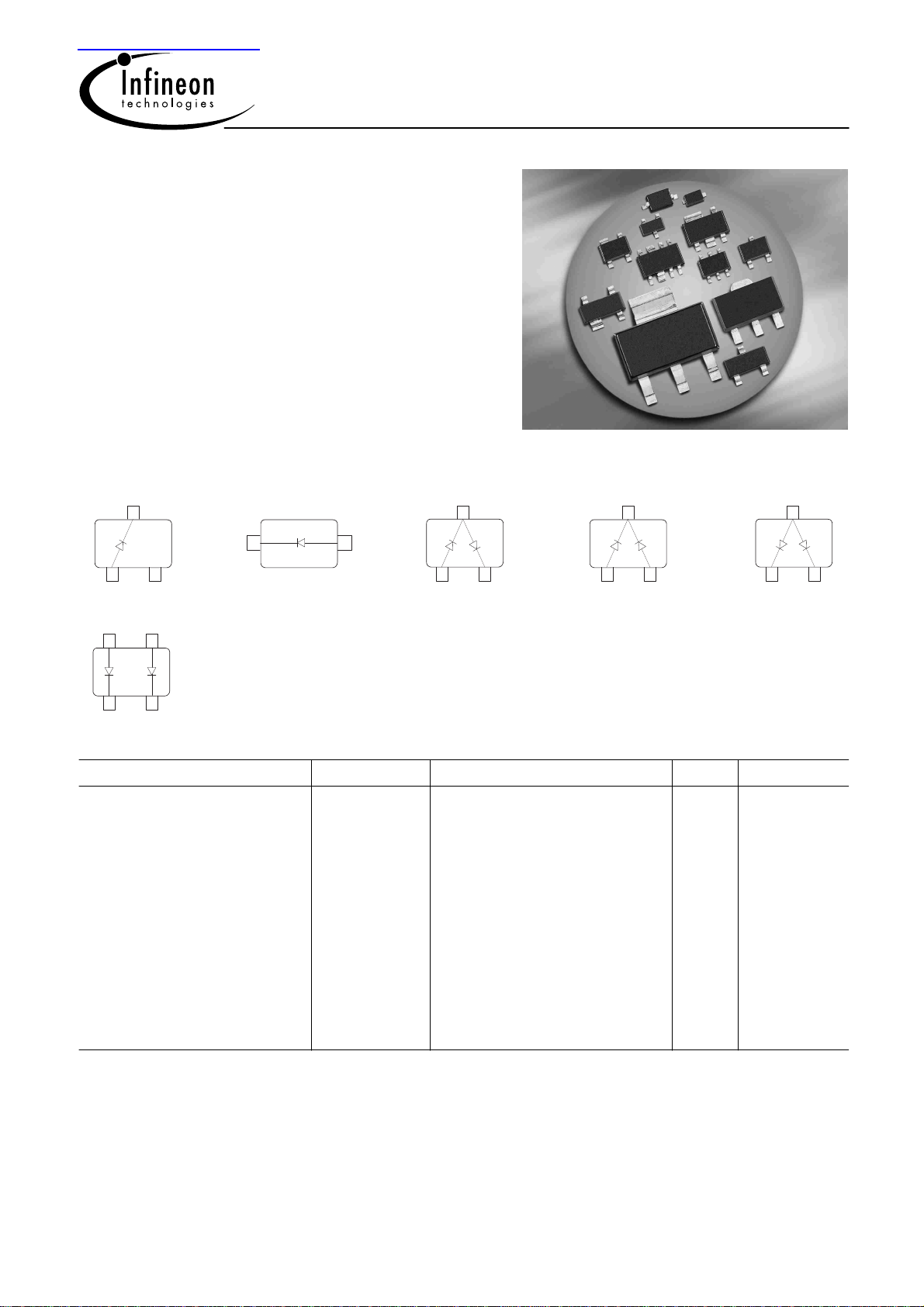
BAT64...
BAT64 BAT64-06
3
1 2
BAT64-02V
BAT64-02W
1 2
BAT64-04
BAT64-04W
3
D 1
D 2
1
2
BAT64-05
BAT64-05W
3
D 2
D 1
1
2
BAT64-06W
3
D 2
D 1
1
2
BAT64-07
34
D 2
D 1
1
2
ESD: Electrostatic discharge sensitive device, observe handling precaution!
Type Package Configuration L
BAT64
BAT64-02V*
BAT64-02W
BAT64-04
SOT23
SC79
SCD80
SOT 23
single
single
single
series
(nH) Marking
S
1.8
0.6
0.6
1.8
63s
t
64
64s
BAT64-04W
BAT64-05
BAT64-05W
BAT64-06
BAT64-06W
BAT64-07
* Preliminary data
SOT323
SOT23
SOT323
SOT23
SOT323
SOT143
series
common cathode
common cathode
common anode
common anode
parallel pair
1
1.4
1.8
1.4
1.8
1.4
2
Mar-10-2004
64s
65s
65s
66s
66s
67s

Maximum Ratings at TA = 25°C, unless otherwise specified
BAT64...
Parameter
Symbol Value Unit
Diode reverse voltage V
Forward current I
Non-repetitive peak surge forward current
I
(t ≤ 10ms)
Average forward current (50/60Hz, sinus) I
Total power dissipation
BAT64, T
BAT64-02V, BAT64-02W, T
≤ 86°C
S
≤ 121°C
S
BAT64-04, BAT64-06, BAT64-07, T
BAT64-04W, BAT64-06W, T
BAT64-05, T
BAT64-05W, T
≤ 36°C
S
≤ 104°C
S
≤ 111°C
S
≤ 61°C
S
P
Junction temperature T
Storage temperature T
R
F
FSM
FAV
tot
j
stg
40 V
250 mA
800
120
250
250
250
250
250
250
150 °C
-55 ... 150
mW
Thermal Resistance
Parameter
Junction - soldering point1)
BAT64
BAT64-02V, BAT64-02W
BAT64-04, BAT64-06, BAT64-07
BAT64-04W, BAT64-06W
BAT64-05
BAT64-05W
1
For calculation of R
please refer to Application Note Thermal Resistance
thJA
Symbol Value Unit
R
thJS
K/W
≤ 255
≤ 115
≤ 355
≤ 155
≤ 455
≤ 185
2
Mar-10-2004

Electrical Characteristics at TA = 25°C, unless otherwise specified
BAT64...
Parameter
DC Characteristics
Breakdown voltage
= 10 µA
I
(BR)
Reverse current
= 30 V
V
R
= 30 V, TA = 85 °C
V
R
Forward voltage
= 1 mA
I
F
= 10 mA
I
F
= 30 mA
I
F
= 100 mA
I
F
AC Characteristics
Diode capacitance
V
= 1 V, f = 1 MHz
R
Symbol Values Unit
min. typ. max.
V
I
V
C
(BR)
R
F
T
40 - - V
-
-
270
310
370
500
-
-
320
385
440
570
2
200
350
430
520
750
- 4 6 pF
µA
mV
Reverse recovery time
I
= 10 mA, IR = 10 mA, measured IR = 1 mA ,
F
R
= 100 Ω
L
t
rr
- - 5 ns
3
Mar-10-2004

BAT64...
Diode capacitance C
f = 1MHz
10
pF
C
T
8
7
6
5
4
3
2
1
0
0
10 20 V 30
= ƒ (V
T
)
R
EHB00059BAT 64...
V
R
Reverse current I
= Parameter
T
A
BAT 64... EHB00058
2
10
A
µ
Ι
R
1
10
0
10
-1
10
-2
10
-3
10
0102030
= ƒ(V
R
)
R
T
A
= 125
85
25
C
C
C
V
V
R
Forward current I
= Parameter
T
A
BAT 64... EHB00057
2
10
mA
Ι
F
1
10
0
10
-1
10
-2
10
0 0.5
= ƒ (V
F
F
T
)
A
= -40
25
85
125
Forward current I
= ƒ (T
F
)
S
BAT64W
300
mA
C
C
C
C
1
V
V
F
200
F
I
150
100
50
0
0 15 30 45 60 75 90 105 120
°C
T
150
S
4
Mar-10-2004

BAT64...
Forward current I
= ƒ (T
F
BAT64-02V, BAT64-02W
300
mA
200
F
I
150
100
50
0
0 15 30 45 60 75 90 105 120
)
S
Forward current I
= ƒ (T
F
)
S
BAT64-04, BAT64-06, BAT64-07
300
mA
200
F
I
150
100
50
°C
T
150
S
0
0 15 30 45 60 75 90 105 120
°C
T
150
S
Forward current I
= ƒ (T
F
BAT64-04W, BAT64-06W
300
mA
200
F
I
150
100
50
0
0 15 30 45 60 75 90 105 120
)
S
Forward current I
= ƒ (T
F
)
S
BAT64-05
300
mA
200
F
I
150
100
50
°C
T
150
S
0
0 15 30 45 60 75 90 105 120
°C
T
150
S
5
Mar-10-2004

BAT64...
Forward current I
BAT64-05W
300
mA
200
F
I
150
100
50
0
0 15 30 45 60 75 90 105 120
= ƒ (T
F
)
S
Permissible Puls Load R
thJS
= ƒ (t
)
p
BAT64-02V, BAT64-02W
3
10
K/W
2
10
thJS
R
°C
T
1
10
0
10
-1
10
150
10
-6
10
-5
S
10
D=0.5
0.2
0.1
0.05
0.02
0.01
0.005
0
-4
10
-3
10
-2
s
t
0
10
P
Permissible Pulse Load
I
Fmax
/ I
FDC
= ƒ (t
)
p
BAT64-02V, BAT64-02W
2
10
FDC
/I
Fmax
I
1
10
0
10
-6
10
10
D=0
0.005
0.01
0.02
0.05
0.1
0.2
0.5
-5
10
-4
10
Permissible Puls Load R
thJS
= ƒ (t
)
p
BAT64-04W, BAT64-06W
3
10
K/W
2
10
thJS
R
1
10
0.5
0.2
0.1
0.05
10
0.02
0.01
0.005
D = 0
-3
10
-2
s
10
0
tP
0
10
-1
-3
10
-2
s
t
0
10
P
10
10
-6
10
-5
10
-4
6
Mar-10-2004

BAT64...
Permissible Pulse Load
I
Fmax
/ I
FDC
= ƒ (t
)
p
BAT64-04W, BAT64-06W
2
10
-
FDC
/I
Fmax
I
1
10
0
10
10
-6
10
-5
10
-4
10
D = 0
0.005
0.01
0.02
0.05
0.1
0.2
0.5
-3
10
Permissible Puls Load R
thJS
= ƒ (t
)
p
BAT64-05W
3
10
K/W
2
10
thJS
R
1
10
0.5
0.2
0.1
0.05
10
0.02
0.01
0.005
D = 0
-3
10
-2
s
10
0
tP
0
10
-1
-2
s
10
0
10
10
-6
10
-5
10
-4
tP
Permissible Pulse Load
I
Fmax
/ I
FDC
= ƒ (t
)
p
BAT64-05W
2
10
-
FDC
/I
Fmax
I
1
10
0
10
10
-6
10
-5
10
-4
10
D = 0
0.005
0.01
0.02
0.05
0.1
0.2
0.5
-3
10
-2
s
t
0
10
p
7
Mar-10-2004
 Loading...