

Page 1

Please read the Important Notice and Warnings at the end of this document
www.infineon.com Page 1 of 9 2019.09.29
Infineon Alarm System (IAS) Mounting
Recommendation
Instructions for placement of the IAS in a room
About this document
Scope and purpose
The document describes the placement of the Infineon Alarm System (IAS) within a room. It also describes the
sensitivity settings and minimum/maximum ratings for relevant parameters. All information refers to productlevel devices on a PCB. The potential impact of the manufacturer’s housing on product performance should be
considered by the manufacturer.
Intended audience
Manufacturers of IAS PCBs.
Table of contents
About this document ....................................................................................................................... 1
Table of contents ............................................................................................................................ 1
1 Introduction ............................................................................................................................. 2
2 Sensitivity setting for the IAS ...................................................................................................... 3
3 Mounting locations .................................................................................................................... 4
3.1 Preferred mounting location ............................................................................................................................. 4
4 Testing of alarm system ............................................................................................................. 5
5 Specifications ........................................................................................................................... 6
Revision history.............................................................................................................................. 8
Page 2
2 of 9
2019.09.29
Infineon Alarm System (IAS) Mounting Recommendation
Introduction
1 Introduction
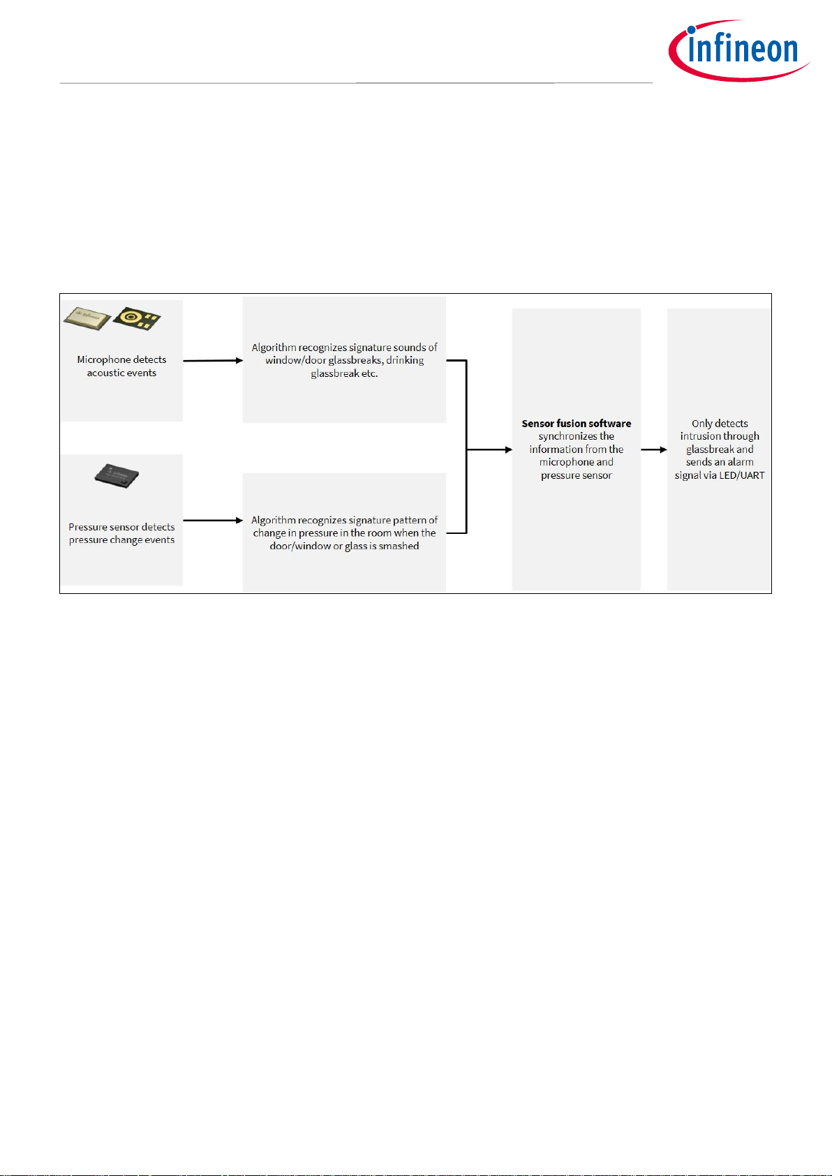
The Infineon Alarm System (IAS) is a true two-sensor alarm system. It monitors acoustic patterns captured by a
microphone and pressure patterns captured by a pressure sensor. Only when both sensors detect the target
pattern is an alarm initiated. This dual-sensor principle enables users to develop alarm systems that are highly
robust against false alarms.
Figure 1 Building blocks of IAS software
Page 3
3 of 9
2019.09.29
Infineon Alarm System (IAS) Mounting Recommendation
Sensitivity setting for the IAS
2 Sensitivity setting for the IAS
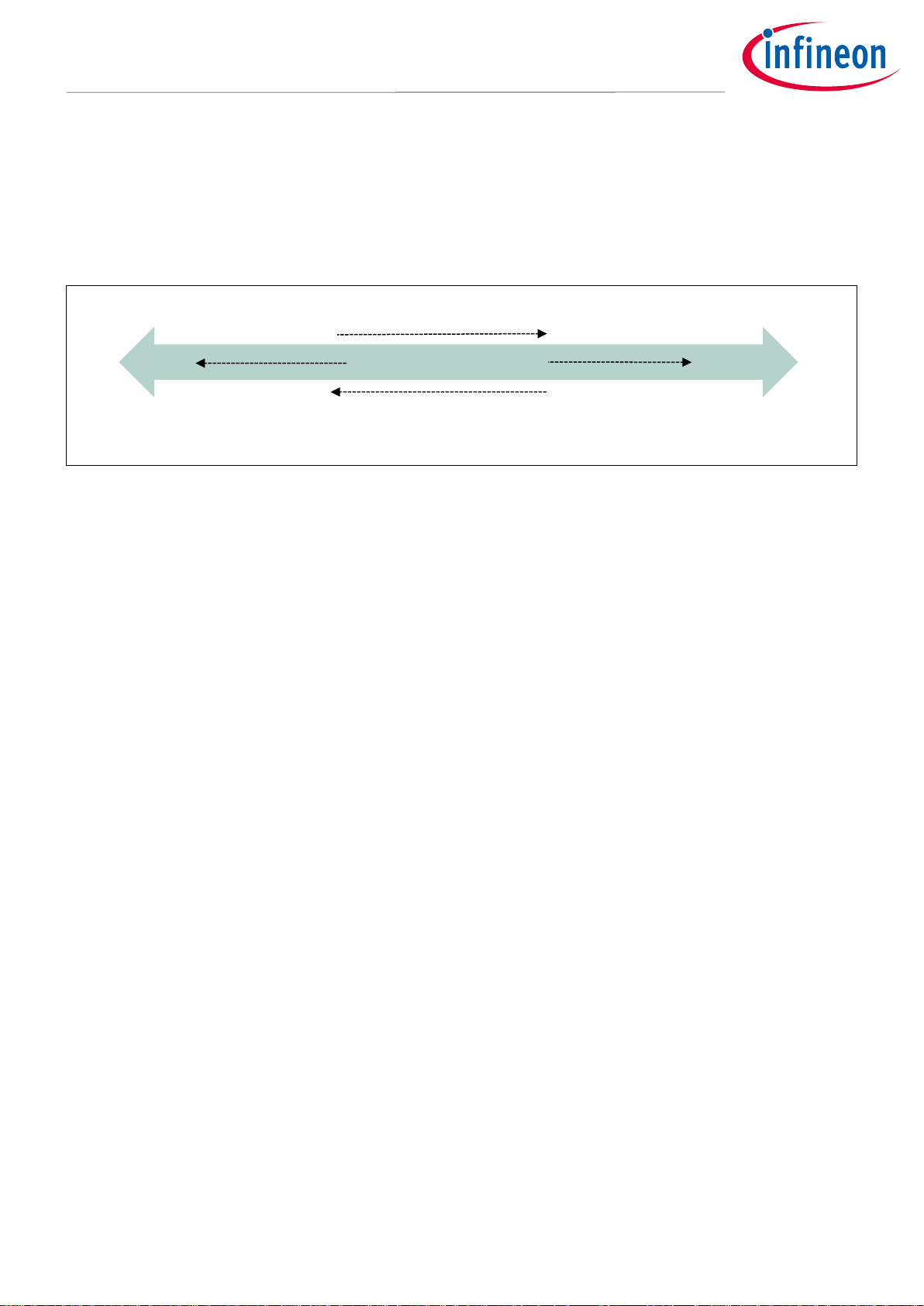
The IAS enables users to adjust the alarm system sensitivity to a level that is most suitable for the specific
environment where the system is used. In its initial state of delivery the system is pre-set to the maximum
sensitivity (sensitivity = 1). This setting provides maximum reception distance, and there can even be objects*
in the line of sight between the alarm system and the window/door to be protected.
Figure 2 Relationship between sensitivity setting and detection range
Even with the sensitivity set to maximum, the IAS is immune to typical audio triggers, for example from TV,
music (stereo speakers) or alarm clocks. By reducing the sensitivity, the IAS provides additional immunity
against very loud sounds, which makes it suitable for use when occupants are in the house.
Note: Reducing the sensitivity also reduces the maximum detection distance and the ability to tolerate
objects in the line of sight.
*Always keep a distance between the IAS and objects in the line of sight e.g. a chair, of at least the
size of the object (Figure 6).
Detection range increases
ca. 1.5 m
ca. 8 m
0
1
Sensitivity setting
Immunity increases
Objects in line of sight
allowed
Very high immunity against
false alarms
Page 4

4 of 9
2019.09.29
Infineon Alarm System (IAS) Mounting Recommendation
Mounting locations
3 Mounting locations
3.1 Preferred mounting locations
The alarm system produces best results when mounted on the wall opposite the window (Figure 3) that is to
be protected/monitored. For mounting on the adjacent walls (refer to Figure 4), the distance of the IAS to the
corner of the wall should be equal to or greater than the distance from the center of the window to the corner
of the wall. A similar distance rule applies to mounting on the ceiling. Mounting the system in other locations,
especially on the same wall as the window, may reduce reception performance.
Note: There is no restriction on the minimum distance from the ground; for example, the alarm system
can be installed at the same level as power sockets.
Figure 3 Preferred mounting location: opposite wall
Figure 4 Mounting location: adjacent wall, same distance rule applies for ceiling mounting
Distance of the IAS
mounted on the adjacent
wall ≥ Distance from the
center of the window to the
corner of the wall (d)
IAS
IAS
Page 5

5 of 9
2019.09.29
Infineon Alarm System (IAS) Mounting Recommendation
Testing of alarm system
4 Testing of alarm system
Once the system has been placed in the desired location, it is recommended to test the alarm system with a
glass break simulator (recommended: Risco ViTRON glass break tester RG65) to verify that it correctly detects
glass break:
Go to the window to be protected/monitored.
Strike a tabletop with the palm of your hand or stamp your foot down on the floor (to create a low-
frequency thud) + initiate glass break sound from simulator device and open the window fast at the
same time (to simulate the right pressure profile).
If the simulated glass break is not detected, a more appropriate location should be selected (Chapter 3) and/or
the sensitivity should be increased (Chapter 2).
Note: The glass break sound from the simulator is very loud; therefore, avoid positioning the simulator
device close to your ear or another person’s ear. For more information see the user manual for
your glass break simulator.
Page 6

6 of 9
2019.09.29
Use Case Conditions
Infineon Alarm System (IAS) Mounting Recommendation
5 Use Case Conditions
For optimal performance of the IAS, follow the recommendations below:
Table 1 Use case conditions for the IAS
Note: All windows and doors to the outside must be closed. It is also recommended to keep doors to
adjacent rooms closed, as leaving them open increases the effective room area, which cannot
exceed the maximum specified area (Figure 5).
Figure 5 Expected maximum room area vs. altitude (above sea level)
Figure 5 shows the expected maximum room area vs. altitude. The curves depicted in Figure 5 are an
extrapolation of real measurements. The maximum room area depends on various window parameters and is
expected to vary for the specified windows (Table 1) between the blue and the orange curve.
Note: For the safest operation the room area should be below the blue curve.
Room size
Min. 22 m³ (e.g. 3 m x 3 m x 2.5 m),
Max. see Figure 5
Window size
Between 0.5 m x 0.5 m and 3 m x 2 m
Distance to the window (depending on sensitivity setting)
Between 1 m and 8 m
Thickness of glass
Between 2.5 mm and 6.5 mm
Type of glass
Plate glass
Page 7

7 of 9
2019.09.29
Use Case Conditions
Infineon Alarm System (IAS) Mounting Recommendation
The room area is shown for a ceiling height of 2.5 m. To calculate the room area for a different ceiling height
follow these calculations:
The alarm system was tested with plate glass; performance might be lower for other glass types.
Room conditions can differ substantially (e.g. due to sound-absorbing material such as carpets,
drapes, etc.) and can reduce the detection range of the alarm system. Therefore it is recommended
to make a test if the system detects glass break in the desired location (Chapter 4).
The IAS should not be installed in environments enclosed on more than one side, e.g. cupboards.
Always install the IAS such that pressure sensor opening is at least 1 m from the vent, drafts or fans
and the pressure sensor is not directly exposed to the airflow of these devices.
When mounted close to the ground, e.g. close to power outlets, the IAS microphone port opening
should not be facing downward. The opening can be on the top or either side of the device.
Always keep a distance between the IAS and objects in the line of sight, e.g. chairs, of at least the
size of the object (Figure 6).
Figure 6 IAS installation recommendation when objects are placed in the line of sight
Warning:
Installation and performance optimization may be affected by the product casing, depending on the casing
design and placement of microphone and pressure sensor inside the casing.
d
Chair
Wall
Height of the chair = d
Distance of the chair from the IAS = d
d
IAS mounted on the wall in a
power outlet/switch
Floor
Page 8

8 of 9
2019.09.29
Revision history
Infineon Alarm System (IAS) Mounting Recommendation
Revision history
Document
version
Date of release
Description of changes
1.0
30.04.2019
Initial release
2.0
09.10.2019
Productive Release Version
Page 9

Published by
Infineon Technologies AG
81726 München, Germany
© 2020 Infineon Technologies AG.
All Rights Reserved.
Do you have a question about this
document?
Email: erratum@infineon.com
UM_1908_PL32_1908_133458
IMPORTANT NOTICE
The information contained in this application note is
given as a hint for the implementation of the product
only and shall in no event be regarded as a
description or warranty of a certain functionality,
condition or quality of the product. Before
implementation of the product, the recipient of this
application note must verify any function and other
technical information given herein in the real
application. Infineon Technologies hereby disclaims
any and all warranties and liabilities of any kind
(including without limitation warranties of noninfringement of intellectual property rights of any
third party) with respect to any and all information
given in this application note.
The data contained in this document is exclusively
intended for technically trained staff. It is the
responsibility of customer’s technical departments
to evaluate the suitability of the product for the
intended application and the completeness of the
product information given in this document with
respect to such application.
For further information on the product, technology,
delivery terms and conditions and prices please
contact your nearest Infineon Technologies office
(www.infineon.com).
WARNINGS
Due to technical requirements products may contain
dangerous substances. For information on the types
in question please contact your nearest Infineon
Technologies office.
Except as otherwise explicitly approved by Infineon
Technologies in a written document signed by
authorized representatives of Infineon
Technologies, Infineon Technologies’ products may
not be used in any applications where a failure of the
product or any consequences of the use thereof can
reasonably be expected to result in personal injury.
Trademarks
All referenced product or service names and trademarks are the property of their respective owners.
 Loading...