

Page 1

Design and Installation Manual for
®
Quick4
Chambers in Minnesota
Angle Inlet
Pinecreek
Pencer
Skime
Four Town
Tabor
Eldred
Averill
High Landing
Beaulieu
Richwood
Lake Itasca
Two Inlets
Pinewood
Ponemah
Clementson
Indus
Loman
Ray
Waskish
Saum
Margie
Crane Lake
Nett Lake
Zim
Alborn
Britt
Embarrass
Arnold
INTRODUCTION 2
PRODUCTS 4
SYSTEM SIZING 8
CHAMBER
CONFIGURATIONS 11
QUICK4 INSTALLATION
TRENCH SYSTEMS 15
SEEPAGE BEDS 18
AT-GRADE SYSTEMS 20
MOUND SYSTEMS 23
QUICK4 PLUS INSTALLATION
TRENCH SYSTEMS 26
PRESSURE SYSTEMS 30
Brushvale
Lawndale
35
Saint Paul
35
Holyoke
90
Leader
Malmo
Pine Center
Collis
94
90
Day
Minneapolis
35
wq-wwists4-57c
DECEMBER 2009
Page 2

INTRODUCTION
The purpose of this manual is to provide minimum specifications for design and installation of Quick4®and Quick4 Plus
chambers approved for use in Minnesota in conformance with the Minnesota Pollution Control Agency (MPCA), design
standards for individual subsurface sewage treatment systems. Each revised version of this design and installation manual
supersedes the previous version. Please contact us or visit our website for more information regarding the most recent
version of this design and installation manual.
For more detailed design and installation information, please contact Infiltrator Systems at 1-800-221-4436.
Quick4 Equalizer®24 LP Chambers
The Quick4 Equalizer 24 LP chamber was designed for shallow
placement applications and can be installed in an 18-inch-wide
or 24-inch-wide trench. The Low Profile End Cap offers a simple
overlap design for easy installation.
Quick4 Equalizer 24 Low Profile (LP)
Nominal Chamber Specifications
Size (W x L x H) 16" x 48" x 8"
Effective Length 48"
Invert Elevation 2", 6”
LOW PROFILE
END CAP
QUICK4 EQUALIZER 24
LOW PROFILE CHAMBER
Quick4 Equalizer 24 Chambers
The Quick4 Equalizer 24 chambers can be installed in an
18-inch-wide or 24-inch-wide trench. The chamber offers
advanced contouring capability with its Contour Swivel
Connection
™
. The MultiPortTMEnd Cap with its six molded-in high
and low inlets allows for maximum piping flexibility.
Quick4 Equalizer 24
Nominal Chamber Specifications
Size (W x L x H) 16" x 48" x 12"
Effective Length 48"
Invert Elevation 6"
Quick4 Equalizer 36 Chambers
The patented Quick4 Equalizer 36 chamber can be installed in a
24-inch-wide trench. The chamber offers advanced contouring
capability with its Contour Swivel Connection. The MultiPort End
Cap with its six molded-in high and low inlets allows for
maximum piping flexibility.
Quick4 Equalizer 36
Nominal Chamber Specifications
Size (W x L x H) 22" x 48" x 12"
Effective Length 48"
Invert Elevation 6"
MULTIPORT
END CAP
MULTIPORT
END CAP
QUICK4 EQUALIZER 24
CHAMBER
QUICK4 EQUALIZER 36
CHAMBER
Page 2 Contact Infiltrator Systems, Inc. 1-800-221-4436 for additional Minnesota technical and product information.
Page 3

INTRODUCTION
Quick4 PlusTMStandard LP Chambers
The Quick4 Plus Standard Low Profile (LP) chamber can be installed in
a 36-inch-wide trench. This chamber is 4 inches shorter than other
standard model chambers allowing for shallower installation. The
Quick4 Plus All-in-One and the Quick4 Plus Endcaps are available with
this chamber, providing increased flexibility in system configurations.
Quick4 Plus Standard Low Profile (LP)
Nominal Chamber Specifications
Size (W x L x H) 34" x 48" x 8"
Effective Length 48"
Invert Elevation 0.6”, 3.3”, 7.3”, 9.0”
Quick4 Plus Standard Chambers
The Quick4 Plus Standard chamber can be installed in a 36-inch-wide
trench. This chamber offers superior strength through its center
structural column. The Quick4 Plus All-in-One and the Quick4 Plus
Endcaps are available with this chamber, providing increased flexibility
in system configurations.
QUICK4 PLUS
ENDCAP
QUICK4 PLUS STANDARD
LP CHAMBER
Quick4 Plus Standard
Nominal Chamber Specifications
Size (W x L x H) 34" x 48" x 12"
Effective Length 48"
Invert Elevation 0.6”, 3.3”, 7.3”, 9.0”
Quick4 Standard Chambers
The Quick4 Standard chamber can be installed in a 36-inch-wide
trench and offers advanced contouring capability with its Contour
Swivel Connection. The MultiPort End Cap has eight molded-in high and
low inlets allowing for maximum piping flexibility. There are a variety
of system inletting options to choose from.
Quick4 Plus Standard
Nominal Chamber Specifications
Size (W x L x H) 34" x 48" x 12"
Effective Length 48"
Invert Elevation 8 ”
Quick4 High Capacity Chambers
The Quick4 High Capacity chamber can be installed in a 36-inch-wide
trench. The MultiPort End Cap has eight molded-in high and low inlets
to allow piping to enter or exit from multiple directions.
QUICK4 ALL-IN-ONE
ENDCAP
MULTIPORT
END CAP
QUICK4 PLUS STANDARD
CHAMBER
QUICK4 STANDARD
CHAMBER
Quick4 Plus High Capacity
Nominal Chamber Specifications
Size (W x L x H) 34" x 48" x 16"
Effective Length 48"
Invert Elevation 11.5”
Contact Infiltrator Systems, Inc. 1-800-221-4436 for additional Minnesota technical and product information. Page 3
QUICK4 HIGH CAPACITY
CHAMBER
Page 4

PRODUCTS
(EFFECTIVE LENGTH)
48"
9" AVG.
Quick4 Equalizer 24 Low Profile (LP) Chambers
SIDE AND END VIEWS
(not to scale)
48"
EFFECTIVE LENGTH
6" AVG.
LOW PROFILE END CAP
(Not to scale)
14” ID
FRONT VIEW
Quick4 Equalizer 24 Chambers
SIDE AND END VIEWS
(not to scale)
MULTIPORT END CAP
(Not to scale)
11"
0.76'
16"
FRONT VIEW
6"
OUTLET*
SIDE VIEW
11"
16"
14" ID
14"
1.12' INLET*
SIDE VIEW
* Installed lengths
Page 4 Contact Infiltrator Systems, Inc. 1-800-221-4436 for additional Minnesota technical and product information.
Page 5
PRODUCTS
Quick4 Equalizer 36 Chambers
SIDE AND END VIEWS
(Not to scale)
(EFFECTIVE LENGTH)
48"
MULTIPORT END CAP
(Not to scale)
12"
6"
22"
FRONT VIEW SIDE VIEW
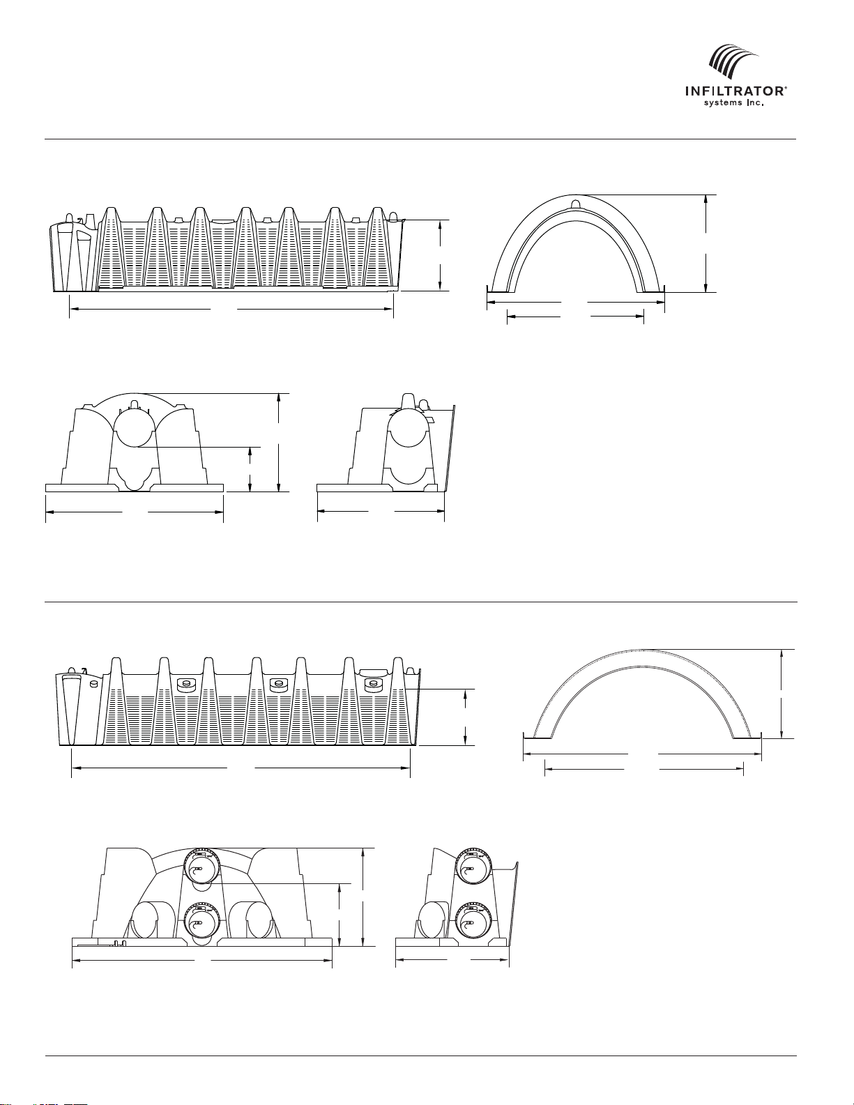
Quick4 Standard Chambers
SIDE AND END VIEWS
(Not to scale)
10" AVG.
12"
22"
19" ID
16"
12"
7" AVG.
34"
(EFFECTIVE LENGTH)
48"
MULTIPORT END CAP
(Not to scale)
12"
8"
34"
Front Side
Contact Infiltrator Systems, Inc. 1-800-221-4436 for additional Minnesota technical and product information. Page 5
16"
29" ID
Page 6

PRODUCTS
Quick4 Plus Standard Low Profile (LP) Chambers
SIDE AND END VIEWS
(Not to scale)
48"
EFFECTIVE LENGTH
Quick4 Plus Standard Chambers
SIDE AND END VIEWS
(Not to scale)
48"
EFFECTIVE LENGTH
Quick4 Plus All-in-One End Cap
SIDE AND END VIEWS
(Not to scale)
6" AVG.
8"
34"
30" ID
Inlet
12"
8" AVG.
34"
30" ID
Inlet
10.4"
17.8"
Front Side
Quick4 Plus End Cap
SIDE AND END VIEWS
(Not to scale)
17.8"
Front Side
Page 6 Contact Infiltrator Systems, Inc. 1-800-221-4436 for additional Minnesota technical and product information.
4.5"
Page 7

PRODUCTS
7
3
Quick4 Invert Adapter
SIDE AND END VIEWS
(Not to scale)
4"
Front
QUICK4 PLUS
ALL-IN-ONE ENDCAP
9"
Side
QUICK4 INVERT A
6.
Quick4 High Capacity Chambers
SIDE AND END VIEWS
(Not to scale)
16"
12" AVG.
34"
(EFFECTIVE LENGTH)
MULTIPORT END CAP
(Not to scale)
Contact Infiltrator Systems, Inc. 1-800-221-4436 for additional Minnesota technical and product information. Page 7
48"
34"
FRONT VIEW
19"
16"
11.5"
0.98'
OUTLET*
1.43' INLET*
SIDE VIEW
29" ID
Page 8

SYSTEM SIZING
Chamber Ratings
For trench applications, the following shall be the basis for establishing equivalency for nominal chamber width to stone and pipe
trench width.
• A 16-inch-wide chamber is equivalent to an 18-inch-wide stone and pipe trench
• A 22-inch-wide chamber is equivalent to an 24-inch-wide stone and pipe trench
• A 34-inch-wide chamber is equivalent to an 36-inch-wide stone and pipe trench
Note: The 34-inch-wide Quick4 High Capacity chamber is eligible for a bottom area reduction under Section 7080.2210, Subpart 3(B).
TABLE 1: TRENCH SIZING FOR CLASSIFICATION I DWELLINGS1AND EFFLUENT TREATMENT LEVEL C
QUICK4 STANDARD, QUICK4 PLUS STANDARD, AND QUICK4 PLUS STANDARD LOW PROFILE (LP) CHAMBERS
SIZING CREDIT PER CHAMBER = 12 SF OR 3 SF/LF
Soil Loading
Rate
2
(gpd/sf)
Number of
Chambers
2 3 4 5
Linear Feet
Number of
Chambers
1.20 21 84 32 128 42 168 52 208
0.78 32 128 48 192 65 260 81 324
0.60 42 168 63 252 84 336 105 420
Number of Bedrooms
Linear Feet
Number of
Chambers
Linear Feet
Number of
Chambers
Linear Feet
0.50 50 200 75 300 100 400 125 500
0.45 56 224 84 336 112 448 139 556
0.24 105 420 157 628 209 836 261 1044
Notes:
1. Sizing for Classification II and III dwellings shall use design flows in Table IV of Section 7080.1850.
2. Soil loading rates and corresponding soil texture groups are based on Table IX and IXa of Section 7080.2150.
3. Rapidly permeable soil textures require conformance with Section 7080.2260, including, but not limited to pressure distribution of effluent.
TABLE 2: TRENCH SIZING FOR CLASSIFICATION I DWELLINGS1AND EFFLUENT TREATMENT LEVEL C
QUICK4 HIGH CAPACITY CHAMBER AT A 20% BOTTOM REDUCTION
SIZING CREDIT PER CHAMBER = 15 SF OR 3.75 SF/LF
Soil Loading
Rate
3
(gpd/sf)
1.20 19
Number of
Chambers
5
2 3 4 5
Linear Feet
Number of
Chambers
76 25 100 34 136 42 168
Number of Bedrooms
Linear Feet
2
Number of
Chambers
Linear Feet
Number of
Chambers
Linear Feet
0.78 26 104 39 156 52 208 65 260
0.60 34 136 50 200 67 268 84 336
0.50 40 160 60 240 80 320 100 400
0.45 45 180 67 268 89 356 112 448
0.24 84 336 125 500 167 668 209 836
Notes:
1. Sizing for Classification II and III dwellings shall use design flows in Table IV of Section 7080.1850.
2. As allowed under Section 7080.2210, Subpart 3(B), a bottom area reduction of 20% has been included in the trench sizing calculation.
3. Soil loading rates and corresponding soil texture groups are based on Table IX and IXa of Section 7080.2150.
4. Rapidly permeable soil textures require conformance with Section 7080.2260, including, but not limited to pressure distribution of effluent.
5. Minimum trench length or number of chambers required by Infiltrator.
6. The drop between the drop box and end cap inlet invert must be equal to or greater than 0.5 inches.
7. The 20% bottom area reduction is only applicable to Infiltrator’s High Capacity chamber models used in trenches.
Page 8 Contact Infiltrator Systems, Inc. 1-800-221-4436 for additional Minnesota technical and product information.
Page 9

SYSTEM SIZING
TABLE 3: AT-GRADE SIZING
Infiltrator Chamber Model
Quick4 Plus Standard Low Profile (LP)
Quick4 Standard
Quick4 Plus Standard
Number of Chambers Spanning At-Grade
Distribution Media Width
1 3
2 6
3 9
4 12
5 15
1 3
2 6
3 9
4 12
5 15
1 3
2 6
3 9
4 12
5 15
At-Grade Design Distribution Media Width (ft)
Notes:
1. At-grade shall be designed by bottom area only.
2. At-grade designs may be utilized when the upper 12 inches of the absorption area contains original soil with a loading rate of 0.45 gallons per day
per square foot or greater, as provided in 7080.2150, Subpart 3(E).
3. At-grade systems may only be installed on slopes less than or equal to 25 percent.
4. For slopes greater than one percent, the design absorption area excludes the area upslope from the top distribution line.
5. The maximum allowable at-grade bed width is 15 feet.
Contact Infiltrator Systems, Inc. 1-800-221-4436 for additional Minnesota technical and product information. Page 9
Page 10

SYSTEM SIZING
TABLE 5: MOUND SIZING
Infiltrator Chamber Model
Quick4 Plus Standard Low Profile (LP)
Quick4 Standard
Quick4 Plus Standard
Notes:
1. Mounds shall be sized by bottom area only.
2. The size of the mound shall be calculated by dividing the design flow by 1.2 gallons per day per square foot.
3. The maximum allowable width for mound distribution media beds is 9 feet.
TABLE 6: SEEPAGE BED SIZING
Infiltrator Chamber Model Number of Chambers Spanning Width Bed Design Width (ft)
Number of Chambers Spanning Mound
Distribution Media Width
1 3
2 6
3 9
1 3
2 6
3 9
1 3
2 6
3 9
Mound Design Distribution Media Width (ft)
Quick4 Plus Standard Low Profile (LP)
Quick4 Standard
Quick4 Plus Standard
Quick4 High Capacity
Notes:
1. When a seepage bed is specified with a design width less than or equal to 12 feet, gravity distribution may be utilized.
2. Seepage bed design greater than 12 feet and up to 25 feet in width require pressure distribution.
TABLE 7: ABSORPTION AREA FOR QUICK4 CHAMBER END CAPS
4 12
8 24
4 12
8 24
4 12
8 24
4 12
8 24
Infiltrator Chamber Model End Cap Model Area Credit
Quick4 Equalizer 24 Low Profile (LP) MultiPort End Cap 0.87 sf/pair
Quick4 Equalizer 24 MultiPort End Cap 2.33 sf/pair
Quick4 Equalizer 36 MultiPort End Cap 3.25 sf/pair
Quick4 Plus Standard Low Profile (LP) Quick4 Plus Endcap 0.56 sf/end cap
Quick4 Plus All-in-One Endcap installed
mid-line with chambers
Quick4 Plus All-in-One Endcap installed
at end of chamber line
1.29 sf/end cap
1.65 sf/end cap
Quick4 Standard MultiPort End Cap 4.62 sf/pair
Quick4 Plus Standard Quick4 Plus Endcap 0.56 sf/end cap
Quick4 Plus All-in-One Endcap installed
mid-line with chambers
Quick4 Plus All-in-One Endcap installed
mid-line with chambers
1.29 sf/end cap
1.65 sf/end cap
Quick4 High Capacity MultiPort End Cap 6.02 sf/pair
Notes:
1. End caps provide additional bottom absorption area.
2. End caps may be cumulatively included as part of the total design area for trench, seepage bed, mound, and at-grade system design when the
design absorption area cannot be reasonably attained with additional chambers, and approved by the local permitting authority.
Page 10 Contact Infiltrator Systems, Inc. 1-800-221-4436 for additional Minnesota technical and product information.
Page 11

CHAMBER CONFIGURATIONS
Trench Systems
CROSS SECTION
(not to scale)
PLAN VIEW
(not to scale)
MOUND FOR PROPER
DRAINAGE
INFILTRATOR
CHAMBER
INFILTRATOR TW-SERIES TANK
AVAILABLE IN 900, 1050, 1250 & 1500 GAL.
TOPSOIL
NATIVE SOIL BACKFILL
34"
36"
TRENCH WIDTH
ESTABLISH VEGETATIVE
COVER
12" MIN
8"
QUICK4 PLUS STANDARD OR
QUICK4 PLUS STANDARD LP CHAMBER (TYP.)
PLAN VIEW
(not to scale)
PER CODE
INFILTRATOR TW-SERIES SEPTIC TANK
AVAILABLE IN 900, 1050, 1250 & 1500 GAL.
LENGTH PER DESIGN
SCHEMATIC LAYOUT ONLY, TRENCH LENGTH AND NUMBER OF
TRENCHES WILL VARY PER DESIGN
DROP BOX
QUICK4 PLUS ALL-IN-ONE ENDCAP (TYP.)
4" PVC PIPE (TYP)
CENTER-TO-CENTER
SPACING PER CODE
INFILTRATOR CHAMBER (TYP)
Contact Infiltrator Systems, Inc. 1-800-221-4436 for additional Minnesota technical and product information. Page 11
Page 12

CHAMBER CONFIGURATIONS
At-Grade Systems
CROSS SECTION: SLOPE < 1%
(not to scale)
6" TOPSOIL (TYP)
QUICK4 CHAMBER
ESTABLISH
VEGETATIVE
COVER
BACKHOE TEETH. SOIL CLODS LARGE ENOUGH TO
PREVENT CHAMBERS FROM LAYING LEVEL ONTO THE
GROUND. SURFACE SHOULD BE BROKEN UP. USE A
RAKE OR SHOVEL TO BREAK UP SUCH SOIL CLODS AS
TO MINIMIZE FOOT TRAFFIC ON THE ABSORPTION AREA.
NATIVE SOIL SHALL BE SCARIFIED WITH
CROSS SECTION: SLOPE > 1%
(not to scale)
4 (TYP)
1
10:1 SLOPE (TYP.)
4" VERTICAL INSPECTION PIPE
NATIVE SOIL
12" MIN. COVER
PRESSURE PIPE PER
DESIGN (TYP)
LOAMY TO SANDY FILL
PER CODE, MIN 6"
ABOVE CHAMBERS
PLAN VIEW
(not to scale)
PRESSURE PIPE
PER DESIGN
INFILTRATOR TW-SERIES SEPTIC TANK
AVAILABLE IN 900, 1050, 1250 & 1500 GAL.
INFILTRATOR TW-375
PUMP TANK
UNIFORMITY IN PRESSURE
DISTRIBUTION ESTABLISHED BY USE
OF PRESSURE VALVES OR VARYING
ORIFICE SIZE WITHIN EACH LATERAL
INFILTRATOR CHAMBER (TYP)
PER DESIGN
Notes:
1. Chamber At-grades on both level and sloping sites require pressure distribution pipes in each row of chambers.
2. The overall Contour Loading Rate for the system must be maintained.
Page 12 Contact Infiltrator Systems, Inc. 1-800-221-4436 for additional Minnesota technical and product information.
Page 13

CHAMBER CONFIGURATIONS
Mound Systems
CROSS SECTION
(not to scale)
MOUND SHALL BE FILLED TO
THE TOP OF THE CHAMBER
INFILTRATOR QUICK4 STANDARD,
QUICK4 PLUS STANDARD or
QUICK 4 PLUS STANDARD LP
CHAMBER (typical)
1
LOUVER HEIGHT
3 (TYP.)
10:1 SLOPE (TYP.)
6" MIN. TOPSOIL
4" VERTICAL INSPECTION PIPE
6" MIN. COVER
SANDY TO LOAMY
SOIL FILL
PRESSURIZED PIPE
ESTABLISH
VEGETATIVE COVER
NATIVE SOIL ROUGHENED PER CODE
MOUND LENGTH IS 1:1 WITH A ROCK MOUND
PLAN VIEW
(not to scale)
INFILTRATOR TW-SERIES SEPTIC TANK
AVAILABLE IN 900, 1050, 1250 & 1500 GAL.
3"
SAND LAYER
DEPTH PER DESIGN
(12" MIN.)
INFILTRATOR TW-375
PUMP TANK
NATIVE SOIL
9'
TO LIMITING ZONE
PRESSURE PIPE
3"
3' MIN.
PER DESIGN
INFILTRATOR QUICK4 CHAMBERS (TYP)
PER DESIGN
Contact Infiltrator Systems, Inc. 1-800-221-4436 for additional Minnesota technical and product information. Page 13
Page 14

CHAMBER CONFIGURATIONS
Seepage Bed Systems (Gravity)
CROSS SECTION
(not to scale)
VERTICAL INSPECTION PIPE
QUICK4
CHAMBER (TYP)
12" MIN. COVER
PLAN VIEW
(not to scale)
INFILTRATOR TW-SERIES SEPTIC TANK
AVAILABLE IN 900, 1050, 1250 & 1500 GAL.
DROP BOX(TYP)
4" PVC PIPE (TYP)
INFILTRATOR CHAMBER (TYP)
Page 14 Contact Infiltrator Systems, Inc. 1-800-221-4436 for additional Minnesota technical and product information.
Page 15

QUICK4 CHAMBERS INSTALLATION
Trench Systems
Before You Begin
Quick4 Chambers may only be installed according to State
and/or local regulations. If unsure of the installation
requirements for a particular site, contact the local unit of
government.
All systems require a design, which includes a thorough site
and soil evaluation of system sizing and the issuance of a
local permit to construct the system. The system installer
must schedule required regulatory inspections.
Materials and Equipment Needed
Quick4 Chambers
End Caps
PVC Pipe and Couplings
Backhoe
Laser, Transit, or Level
Shovel and Rake
Tape Measure
Utility Knife
These guidelines for construction machinery must be
followed during installation:
Avoid direct contact with chambers when using
construction equipment. Chambers require a 12-inch
minimum of compacted cover to support a wheel
load rating of 16,000 lbs/axle or equivalent to an
H-10 AASHTO load rating.
Only drive across the trenches when necessary.
Never drive down the length of the trenches.
To avoid additional soil compaction, do not drive
vehicles over the completed system.
Hole Saw*
2-inch Drywall Screws*
Screw Gun*
Small Valve-Cover Box*
4-inch Cap for
Inspection Port*
* Optional
Excavating and Preparing the Site
Note: As is the case with conventional systems, do not install
the systems in wet conditions or in overly moist soils, as this
causes machinery to smear the soil.
Note: Raking to eliminate smearing is not necessary in
sandy soils. In fine textured soils (silts and clays), avoid
walking in the trench to prevent compaction and loss of
soil structure.
5. Verify that the bottom of the system is level using a level,
transit, or laser.
Preparing the MultiPort End Cap
1. With a utility knife start
the tear-out seal at the
appropriate diameter for
the inlet pipe. The seal
allows for a tight fit for
3-inch, 4-inch SDR35,
and 4-inch Schedule 40
pipe.
2. Pull the tab on the
tear-out seal to create an
opening on the end cap.
3. Snap off the molded
splash plate located on the
bottom front of the end cap.
4. Install splash plate into
the appropriate slots below
the inlet to prevent bottom
erosion of the system.
5. Insert the inlet pipe into
the end cap at the beginning of the chamber line.
The pipe will go in several
inches before reaching a
stop. (Screws optional.)
1
Start tear-out seal.
4
Install splash plate.
1. Stake out the location of all chamber lines. Set the
elevations of the tank, pipe, and system bottom.
2. Install sedimentation and erosion control measures.
Temporary drainage swales/berms may be installed to protect
the site during rainfall events.
3. Excavate and level the trenches with proper center-to-center
sep aration. Verify that the bottom of the system is level and that
it is at least 3 feet abov e the limiting layer.
Note: Over excavate the trench width in areas where the
chamber line will contour.
4. Rake the bottom and sides if smearing has occurred while
excavating. Remove any large stones and other debris. Do not
use the bucket teeth to rake the trench bottom. Minimize or
avoid walking in the trench to prevent compaction, loss of soil
structure, and the subsequent reduction in the soil’s infiltrative
capacity.
Contact Infiltrator Systems, Inc. 1-800-221-4436 for additional Minnesota technical and product information. Page 15
Preparing the Low Profile End Cap
1. With a hole saw, drill an opening appropriate for the pipe
diameter being used (normally 3 to 4 inches) on the front of the
end cap.
2. Snap off the molded splash plate located on the bottom front
of the end cap.
3. Install splash plate into the appropriate slots below the inlet
to prevent trench bottom erosion.
5
Insert inlet pipe.
Page 16

QUICK4 CHAMBERS INSTALLATION
Installing the System
For installing the Quick4 Equalizer Low Profile (LP) Chamber,
see Installing the System with Q4 EQ24 LP section.
1. Check the inlet pipe to be sure it is level or has the
prescribed slope. It may be firmly supported on a solid base
of unexcavated soil (not required).
Note: If possible, avoid walking in the trench to minimize disturbance of the soil structure and loss of infiltrative capacity.
Rake any areas where foot traffic has occured in the trench.
2. Place the inlet end of the
first chamber over the back
edge of the end cap so that
the chamber overlaps the
end cap when in place.
3. Lift and place the end of
the next chamber onto the
previous chamber by holding it at a 45-degree angle.
Line up the chamber end
between the connector
hook and locking pin at
the top of the first chamber. Lower it to the ground
to connect the chambers.
Note: When the chamber
end is placed between
the connector hook and
locking pin at a 45-degree
angle, the pin will be
visible from the back
side of the chamber.
Note: The connector hook
serves as a guide to insure
proper connection and
does not add structural
integrity to the chamber joint. Broken hooks will not affect the
structure nor void the warranty.
4. Swivel the chamber on the pin to the proper direction for
the trench layout.
Note: The Quick4 Standard chamber and Quick4 High
Capacity chamber allow 10º of swivel in either direction at
each joint. The Quick4 Equalizer 36 and Quick4 Equalizer 24
allow for 15º of swivel.
Note: If installing the Quick4 High Capacity chamber with the
20% bottom area reduction allowed in the product registration, make sure to provide at least 0.5-inches of fall from the
drop box outlet to the end cap inlet to allow full use of the 12inch sidewall profile (see drawing).
2
Place first chamber onto end cap.
3
Connect the chambers.
5. Continue connecting the
chambers until the chamber
line is completed.
Note: As chambers are
installed, verify they are level.
6. The last chamber in the
trench requires an end cap.
Lift the end cap at a 45degree angle and insert the
connector hook through the
opening on the top of the
end cap. Applying firm
6
Attach end cap to chamber.
pressure, lower the end cap
to the ground to snap it into place. Do not remove the
tear-out seal.
7. To ensure structural stability, fill the sidewall area by pulling
soil from the sides of the trench with a shovel. Start at the
joints where the chambers connect. Continue backfilling the
entire sidewall area, making sure the fill covers the louvers.
8. Pack down the fill by walking along the edges of the
chambers.
9. Proceed to the next chamber line and begin with Step 1.
Installing the System with Q4 EQ24 LP
1. Place the first chamber in the trench.
2. Place the back edge of the end cap over the inlet end of
the first chamber. Be sure to line up the locking pins on the
top of both the chamber and end cap.
Optional: Fasten the end cap to the chamber with a screw at
the top of the end cap.
3. Insert the inlet pipe 2.5 inches into the opening on the front
of the end cap.
4. Lift and place the end of
the next chamber onto the
previous chamber by holding it at a 45-degree angle.
Line up the chamber end
between the connector
hook and locking pin at the
top of the first chamber.
Lower the chamber to the
ground to connect the
chambers.
Note: When the chamber end is placed between the
connector hook and locking pin at a 45-degree angle, the
pin will be visible from the back side of the chamber.
Note: The connector hook serves as a guide to ensure
proper connection and does not add structural integrity to
the chamber joint. Broken hooks will not affect the structure
or void the warranty.
5. For a trench layout, swivel the chamber on the pin to
achieve the proper direction for the chamber line.
6. Continue connecting the chambers until the trench is
completed.
4
Connect chambers.
Page 16 Contact Infiltrator Systems, Inc. 1-800-221-4436 for additional Minnesota technical and product information.
Page 17

QUICK4 CHAMBERS INSTALLATION
Attaching the Q4 EQ24 LP End Caps
1. Lift the end cap at a
45-degree angle and align
the connector hook on the
top of the chamber with
the raised slot on the top
of the end cap. Lower the
end cap to the ground
and into place.
Note: Place a few shovels
of soil around the end cap
to secure it during backfill.
1
Attach end cap to last chamber.
Installing Inspection Ports
1. With a hole saw, drill the pre-marked area in the top of the
chamber to create a 4-inch opening.
2. Set a cut piece of pipe of the appropriate length into
the corresponding chamber’s inspection port sleeve.
Note: The sleeve will accommodate a 4-inch Schedule 40 pipe.
3. Use two screws to fasten
the pipe to the sleeve
around the inspection port.
4. Attach a threaded cap or
cleanout assembly onto the
protruding pipe at the
appropriate height.
5. A small valve cover box
may be used if inspection
port is below the desired
grade.
3
Fasten the pipe.
Covering the System
Before backfilling, the system must be inspected by the
local unit of governmentʼs SSTS Inspector as per local
ordinance requirements. Create an as-built drawing at
this time for future records.
1. Apply the backfill
material along the sides
of the chambers and walk
the soil in.
1
Walk the soil in.
2. Continue backfilling the
soil to the top of chambers.
Note: When backfilling a
wide excavation or soil
substitution system use a
dozer, small box blade or a
tracked Bobcat machine.
2
Backfill the soil.
INSPECTION PORT DETAIL (Not to scale)
SMALL VALVE COVER
BOX OR IRRIGATION
VALVE BOX AT GRADE
COMPACT SOIL BASE
TO SUPPORT BOX
USE HOLE SAW TO CUT
OUT PRE-MARKED CIRCLE.
Contact Infiltrator Systems, Inc. 1-800-221-4436 for additional Minnesota technical and product information. Page 17
ATTACH CAP OR THREADED
CLEANOUT ASSEMBLY.
4" PVC PIPE
CUT TO FIT
REST 4" PVC PIPE ON TOP
OF INSPECTION PORT
SEAT. SECURE IN PLACE
WITH A DRYWALL SCREW.
Page 18

QUICK4 CHAMBERS INSTALLATION
Seepage Bed Systems
Before You Begin
This document provides septic installation instructions for
Quick4 chambers in bed systems. These chambers may
only be installed according to state and local regulations. If unsure of the installation requirements, contact
the local unit of government.
All systems require a design, which includes a thorough
site and soil evaluation, system sizing, and the issuance
of a local permit to construct the system.
Materials and Equipment Needed
Quick4 Chambers
End Caps
Backhoe/Bulldozer
4-inch PVC Pipe and
Couplings
Laser, Transit, or Level
These guidelines for construction machinery must be
followed during installation:
Avoid direct contact with chambers when using
construction equipment. Chambers require a 12-inch
minimum of compacted cover to support a wheel load
rating of 16,000 lbs/axle or equivalent to an H-10
AASHTO load rating.
Only drive across the bed when necessary. Never
drive down the length of the bed system.
Prior to compaction and during backfill, only use
tracked vehicles. Always keep 6 inches of soil between
tracks and chambers.
Shovel and Rake
Tape Measure
Utility Knife
Hole Saw/Router Bit*
D-Box*
* Optional
2. Excavate and level the designated area. Be sure to excavate
at least one extra foot around perimeter to allow for proper fit
and ease installation.
3. If required, be sure to dig through any restrictive layer to
the more suitable soils. Remove any debris from the bed walls.
Prepare the chamber bed’s sub grade soil as outlined in the
designer’s plans.
4. Rake the bottom and sides if smearing has occurred while
excavating. Verify the bottom of the bed is level using a transit, laser or level. Minimize or avoid walking on the bottom of
the bed to prevent compaction, loss of soil structure and the
subsequent reduction in the soil’s infiltrative capacity.
5. If pressure distribution is required, refer to the “Pressure
Pipe Design Options” instructions provided in the Mound
Systems section.
Preparing the End Caps
1. With a utility knife start the
tear-out seal at the appropriate diameter for the inlet
pipe. The seal allows for a
tight fit for 3-inch, 4-inch
SDR35 and 4-inch SCH40
pipe. A 2-inch line can be
installed by using an
appropriately sized hole
saw to cut an opening in
the end cap.
Note: Pipe size may vary
according to state/county regulations
or designer specifications.
1
Start tear-out seal.
TYPICAL BED SYSTEM (plan view)
CHAMBER SPACING
PER CODE
34"
REAR (LOOP)
MANIFOLD (OPTIONAL)
QUICK4 CHAMBER
QUICK4 MULTIPORT
LENGTH VARIES PER DESIGN
END CAPS (TYP.)
SEPTIC
TANK
D-BOX
Excavating and Preparing the Site
Note: It is not recommended to install systems in wet conditions or in overly moist soils, as this causes machinery to
smear the soil interface which can affect system performance.
1. Stake out the location of the bed and set the elevations of
the tanks, pump chamber (if required), pre-treatment devices
(if required), piping, and bed bottom. Install sedimentation
and erosion control barriers as necessary.
2. Pull the tab on the tear-out
seal to create an opening on
the end cap.
3. Snap off the molded
splash plate located on the
bottom front of the end cap.
4. Install splash plate into
the appropriate slots below
the inlet to prevent trench
bottom erosion.
2
Pull tab on tear-out seal.
5. Construct a manifold to
inlet each row of chambers.
A d-box may be used if
required by code or
designer preference.
Note: It is sometimes easier
to install the chamber bed
before constructing the
manifold. If installing the
chambers first in a gravity
fed system, it is critical to
4
Install splash plate.
ensure there is proper fall
from the tank to accommodate a manifold.
Page 18 Contact Infiltrator Systems, Inc. 1-800-221-4436 for additional Minnesota technical and product information.
Page 19

QUICK4 CHAMBERS INSTALLATION
6. Once piping network is complete, insert pipe into the end
cap at the beginning of each row of the bed.
7. Attach a closed end cap onto the outlet end of the chamber.
Do not create an opening on the closed or outlet end cap.
Installing the Bed System
1. Construct the chamber bed
by joining chambers. Place
the inlet end of the first chamber over the back edge of the
end cap.
2. Lift and place the end of
the next chamber on to the
previous chamber by holding it at a 90-degree angle.
Line up the chamber end
between the connector hook
and locking pin at the top of
the first chamber. Lower to
the ground to connect the
chambers.
Note: When the chamber
end is placed between the
connector hook and locking
pin at a 90-degree angle, the
pin will be visible from the
back side of the chamber.
Note: The connector hook
serves as a guide to ensure
proper connection and does
not add structural integrity to the chamber joint. Broken hooks
will not affect the structure nor void the warranty.
3. Continue connecting the chambers until the first row is
completed.
4. Check the first row of chambers to be sure that it is level.
5. Continue connecting chambers until the bed is complete.
As the chambers are installed, verify that they are level,
straight and maintain the required separation distance
between each row of chambers.
Note: After installing chambers edge to edge or with up to 6" of
spacing, it is important to properly backfill per current installation instructions so as to not compromise the integrity of the
product.
6. The last chamber in the row requires an end cap. Lift the
end cap at a 45-degree angle and insert the connector hook
through the opening on the top of the end cap. Applying firm
pressure, lower the end cap to the ground to snap it into place.
Do not remove the tear out seal if ends are not to be connected.
Repeat this step for each row in the bed.
Note: Looping the outlet end of the bed may be required or
specified by design. Infiltrator Systems recommends creating a
hole in the end cap at the specified invert height.
7. Insert the loop manifold through the end cap and
determine that the manifold is level before backfilling.
1
Place first chamber onto end cap.
2
Connect the chambers.
8. Bed systems require at least one vertical inspection pipe.
Refer to the “Installing Inspection Ports” instructions provided
in the Trench Systems section.
9. To ensure structural stability, fill the sidewall area by pulling
soil in from the sides of the bed with a shovel or by placing fill
material with a backhoe or excavator bucket.
10. Continue to carefully anchor chambers by ladling fill material between the chamber rows making sure not to dislodge the
units. Be sure the fill extends above the louvers a minimum of
two inches.
Note: Only drive over the system with a tracked v ehicle.
Note: Do not to drive over the chambers until a minimum of
12" of fill is placed above the chambers. For rows not accessible from the edge of the bed, wait until a majority of the chambers are covered with 6" of fill before stabilizing middle rows
(for tracked vehicles only).
11. Pack down the fill by walking along the sidewalls of the
chambers as this helps to give better structural support. In wet
conditions, silty or clay soils, do not walk in the sidewalls.
Covering the System
Before backfilling, the system must be inspected by the
local unit of governts SSTS inspector as per local ordinance
requirements.
1. Backfill the chamber sys-
tem by pushing or ladling
the fill material onto the units
with a backhoe or bulldozer.
Be sure to avoid having
large rocks in backfill.
Note: For large bed systems
that cannot be filled from the
sides, use a light tracked
vehicle making sure to maintain a minimum of cover of 6"
between the chambers and tracks at all times.
2. Do not drive wheeled vehicles across the system when
applying cover material.
Note: Chambers can be installed with a minimum of 6 inches of
cover using light tracked vehicles. A maximum of 4 feet of cover is
allowed for bed systems.
3. Leave several inches of soil above the required amount for
settling and to divert runoff water from the system.
4. After the system is covered, the site should be seeded or
sodded to prevent erosion.
TYPICAL STANDARD BED SYSTEM (front view)
QUICK4
CHAMBER (TYP)
Note: All Infiltrator chambers currently registered for use in
Minnesota are allowed for use in bed systems.
1
VERTICAL INSPECTION PIPE
Ladle the fill.
12" MIN. COVER
Contact Infiltrator Systems, Inc. 1-800-221-4436 for additional Minnesota technical and product information. Page 19
Page 20

QUICK4 CHAMBERS INSTALLATION
At-Grade Systems
Before You Begin
Quick4 chambers can only be installed according to
state or county regulations. Contact your local unit of
government for specific requirements.
Materials and Equipment Needed
Quick4 Chambers and End Caps
Pressure Lateral Pipe and Fittings
Sand and Specified Fill Material
Plastic Pipe straps, all weather, 120 lb. tensile
strength (nylon prohibited)
Utility Knife or Hole Saw
Backhoe/Bulldozer/Skid-Steer
Glue
Rake
2" Drywall Screws*
Garden Hose*
Chisel Plow*
Paving Block*
* Optional
These guidelines for construction machinery
must be followed during installation:
Avoid direct contact with chambers when using
construction equipment. Chambers require a 12inch minimum of compacted cover to support a
wheel load rating of 16,000 lbs/axle or equivalent to
an H-10 AASHTO load rating.
Only drive across sand mound when necessary.
Never drive wheeled machinery over chambers.
Avoid stones larger than 3 inches in diameter in
backfill. Remove stones this size or larger that are
in contact with chambers.
Preparing the Site
1. Review approved system design to determine the height
of the seasonal high water table or other limiting factors.
2. Stake out the site for At-grade system placement.
3. Install sedimentation and erosion control measures.
4. Cut trees flush to the ground, remove surface boulders
that can be easily rolled off, and remove vegetation per
code requirements.
5. The original At-Grade absorption area must be scarified
by backhoe teeth, moldboard, or chisel plow.
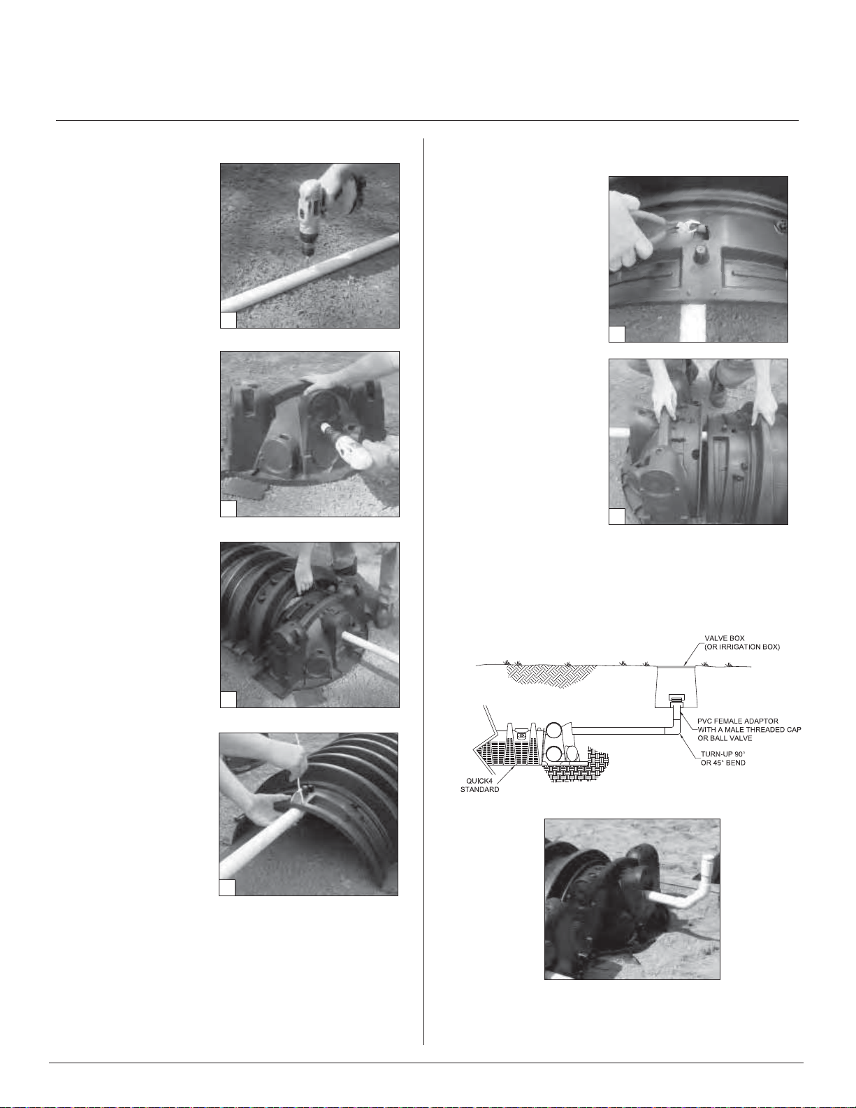
Installing Chambers and End Caps
1. To allow pressure laterals to drain after each dose, drill a
hole in the bottom of the pipe at the end of the pressure
line. Place the snap-off splash plate, gravel or a paving
block at the bottom of the trench to protect the infiltrative
surface from erosion.
2. With a hole saw, drill out
the appropriate diameter
hole in the end cap to
accommodate the
pressure lateral pipe.
3. Each chamber row shall
require a pressure distribution pipe.
4. Insert the pressure lateral
pipe into the end cap’s
drilled opening and slide it
into the manifold pipe.
Glue the pressure lateral
pipe to the manifold pipe.
5. With the pressure lateral
pipe through the end cap,
place the inlet end of the
first chamber over the
back edge of the end cap.
6. Secure the pressure lateral pipe to the top of the
first chamber with a plastic
pipe strap at the outlet end
of the unit. Slide the strap
up through a slot in the
chamber top, down
through the other slot, and
cinch the two ends around
the pipe.
7. Lift and place the next
chamber onto the previous
one at a 90-degree angle.
Line up the chamber end
between the connector
hook and locking pin at
the top of the first
chamber. Lower it to the
ground to engage the
interlocks. Make sure that
the connected chambers
are level with the absorption surface area.
8. Secure the lateral pipe
to the top of the next
chamber once in place.
Follow the same method
in Step 6.
9. Continue interlocking chambers and securing the pipe
until the row is completed.
10. Before attaching the final end cap, remove the tongue
of the connector hook on the last chamber with a pair of
pliers.
1
2
4
6
Page 20 Contact Infiltrator Systems, Inc. 1-800-221-4436 for additional Minnesota technical and product information.
Page 21
QUICK4 CHAMBERS INSTALLATION
11. Insert the pressure
lateral pipe through the
hole in the final end cap
and slide the end cap
towards the last chamber.
Lift the end cap over the
modified connector hook
and push straight down
to secure it to the chamber.
Note: If cleanout exten-
11
sions are required, use a
hole saw to cut a hole in the end cap at the proper elevation
so that the lateral pipe can extend. For clean-out access, a
90-degree long sweep or 45-degree bend elbow that
extends to the soilʼs surface can be attached to the lateral
pipe.
12. If installing multiple rows of chambers on a slope each
row must be installed along the slope and covered with
geotextile to prevent soil intrusion into the up slope sidewall.
ACCESS FOR DRAINFIELD MAINTENANCE AND FLUSHING
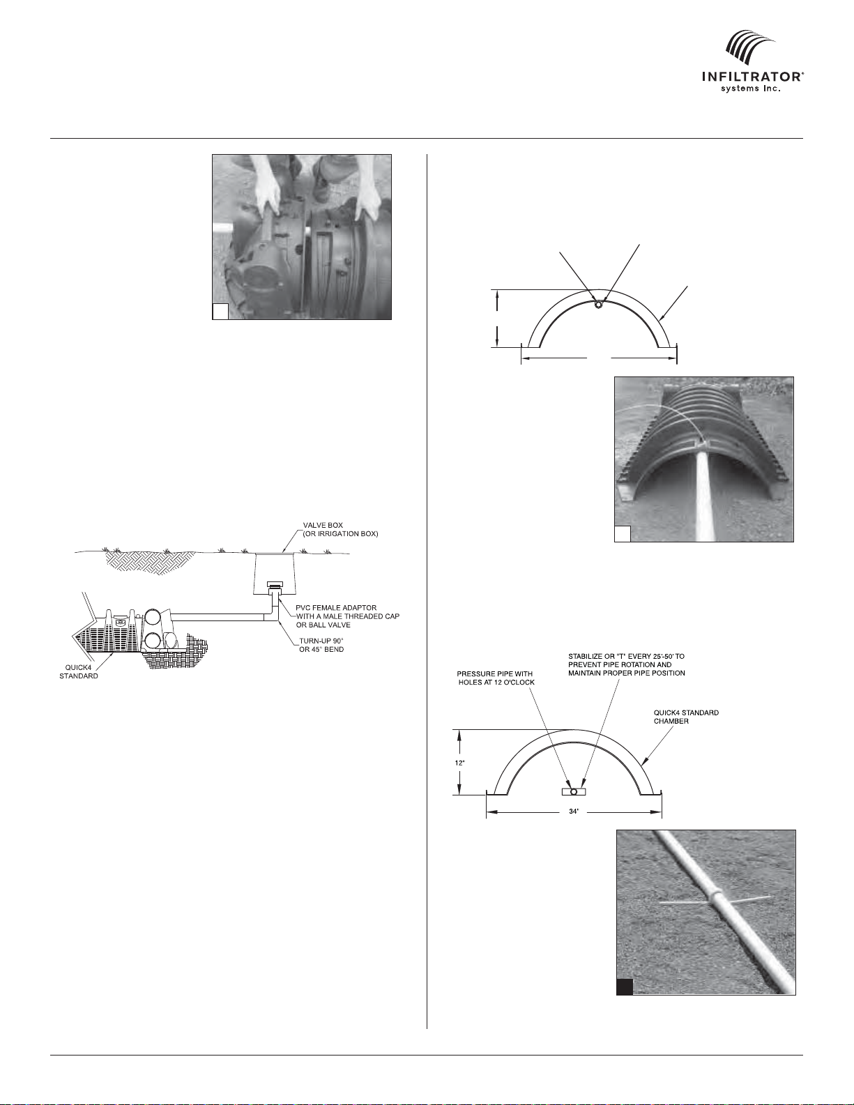
Pressure Pipe Design Options
METHOD A: TOP PLACEMENT
ALL WEATHER PLASTIC PIPE STRAP
WITH 120 POUNDS TENSILE STRENGTH
PRESSURE PIPE WITH
HOLES AT 12 O’CLOCK
12"
Advantages of Method A
• Pipe and orifice placed
closer to the chamber
dome offer improved
distribution.
• Pipe positioned at the
top of the chamber
places it well above
effluent.
• Plastic pipe hanger
easily secures pipe
in place.
• If necessary, trim excess plastic pipe strap before connecting chambers.
AT EVERY CHAMBER CONNECTION
QUICK4 STANDARD
34"
A
METHOD B: BOTTOM PLACEMENT
Advantages of Method B
• Pipe resting on the
mound distribution media
bed allows easy installation and maintenance.
• Glue “T’s” or PVC Jhooks to keep pipe level.
• System promotes efficient
pressure checks.
• Pipe resting on the trench
bottom allows easier
B
inspection if monitoring
ports are installed.
Contact Infiltrator Systems, Inc. 1-800-221-4436 for additional Minnesota technical and product information. Page 21
Page 22

QUICK4 CHAMBERS INSTALLATION
Covering the System
Before backfilling, the system must be in spected by the
local unit of governmentʼs SSTS Inspector as per local
ordinance requirements. System should be installed as
per design.
1. For sites sloping greater than 1%, a geotextile fabric of
at least 3-feet in width shall be placed over the upslope
sidewall and chamber top to prevent intrusion of fill. A
getextile fabric spanning the width of the dispersal area
and covering each chamber row may be used.
2. Place a 2-foot high pile of berm material around the
perimeter of the At-Grade and directly against the outer
rows of chambers for stabilization.
3. Ladle clean sand between the chamber rows to the top
sidewall louver to prevent chamber movement before final
backfill. Firm the soil between the chamber rows by walking
it in.
4. Push the berm material between and over the
chamber rows with a tracked vehicle from the upslope side.
Keep a minimum 12-inches of densified cover over the
system.
Note: NO wheeled machinery is allowed on chambers in AtGrades. Tracked vehicles may be used.
5. After the system is covered, the site shall be seeded or
sodded per 7080.2150 Subp 3.J. to prevent erosion.
Note: If the system is for new home construction, it is important
to place marking stakes along the boundary of the
system. This will notify contractors of the site location so they will
not cross it with equipment or vehicles.
Page 22 January 2006 Contact Infiltrator Systems, Inc. 1-800-221-4436 for additional Minnesota technical and product information.
Page 23

QUICK4 CHAMBERS INSTALLATION
Mound Systems
Before You Begin
Quick4 chambers can only be installed according to
state or county regulations. Contact your local unit of
government for specific requirements.
All systems require a design, which includes a thorough
site and soil evaluation of system sizing and the issuance of
a local permit to construct the system. The system installer
must schedule required regulatory inspections
Materials and Equipment Needed
Quick4 Chambers and End Caps
Pressure Lateral Pipe and Fittings
Sand and Specified Fill Material
Plastic Pipe straps, all weather, 120 lb. tensile
strength (nylon prohibited)
Utility Knife or Hole Saw
Backhoe/Bulldozer/Skid-Steer
Glue
Rake
2" Drywall Screws*
Garden Hose*
Chisel Plow*
Paving Block*
* Optional
These guidelines for construction machinery
must be followed during installation:
Avoid direct contact with chambers when using
construction equipment. Chambers require a 12inch minimum of compacted cover to support a
wheel load rating of 16,000 lbs/axle or equivalent to
an H-10 AASHTO load rating.
Only drive across sand mound when necessary.
Never drive wheeled machinery over chambers.
Avoid stones larger than 3 inches in diameter in
backfill. Remove stones this size or larger that are
in contact with chambers.
Preparing the Site
1. Review approved system design to determine the height
of the seasonal high water table or other limiting factors.
2. Calculate the number of sand lifts necessary. Lifts should
measure 6 to 12 inches in height.
3. Confirm that the sand used to build the mound meets
Minnesota design standards. Sand must meet requirements
of Chapter 7080.2220, subpart.3. (C).
4. Stake out the site for mound placement.
5. Install sedimentation and erosion control measures.
6. Cut trees flush to the ground, remove surface boulders
that can be easily rolled off, and remove vegetation per
code requirements.
7. The original soil mound absorption area must be roughened by backhoe teeth, moldboard, or chisel plow. The soil
must be roughened to a depth of eight inches.
Placing the Sand
1. After placement of six
inches of clean sand, use
a crawler or track-type
tractor to evenly spread a
one-foot lift of specified fill
material over required
area.
Note: Firming up the fill is
critical to prevent settling
and will not have a significant effect on permeability
of clean, sandy fill.
2. To firm up the fill, a crawler or track-type tractor can be
driven over the entire bed. After first tracks are made
across the bed, move across the bed at increments equal
to the width of the wheels/ tracks.
3. Place consecutive lifts following Steps 1 and 2 until
design elevation is achieved (desired elevation is the infiltrative surface). Lifts should not exceed a 12 inch height.
4. Lightly drag a landscape rake over the final infiltrative
surface to scarify the top
elevation to be sure it is level and has the correct depth of
clean sand in accordance with the approved system
design.
1
1
⁄2 inch of the sand. Check bed
Contact Infiltrator Systems, Inc. 1-800-221-4436 for additional Minnesota technical and product information. Page 23
Page 24
QUICK4 CHAMBERS INSTALLATION
Installing Chambers and End Caps
1. To allow pressure laterals
to drain after each dose,
drill a hole in the bottom of
the pipe at the end of the
pressure line. Place the
snap-off splash plate,
gravel or a paving block at
the bottom of the trench to
protect the infiltrative surface from erosion.
2. With a hole saw, drill out
the appropriate diameter
hole to accommodate the
pressure lateral pipe.
3. Insert the pressure lateral
pipe into the end cap’s
drilled opening and slide it
into the manifold pipe.
Glue the pressure lateral
pipe to the manifold pipe.
4. With the pressure lateral
pipe through the end cap,
place the inlet end of the
first chamber over the
back edge of the end cap.
5. Secure the pressure lateral pipe to the top of the
first chamber with a plastic
pipe strap at the outlet
end of the unit. Slide the
strap up through a slot in
the chamber top, down
through the other slot, and
cinch the two ends around
the pipe.
6. Lift and place the next
chamber onto the previous one at a 90-degree
angle. Line up the chamber end between the connector hook and locking
pin at the top of the first
chamber. Lower it to the
ground to engage the
interlocks.
7. Secure the lateral pipe
to the top of the next
chamber once in place. Follow the same method in Step 5.
8. Continue interlocking chambers and securing the pipe
until the row is completed.
1
2
4
5
9. Before attaching the final end cap, remove the tongue of
the connector hook on the last chamber with a pair of pliers.
10. Insert the pressure
lateral pipe through the
hole in the final end cap
and slide the end cap
towards the last chamber.
Lift the end cap over the
modified connector hook
and push straight down to
secure it to the chamber.
Note: If cleanout exten-
9
sions are required, use a
hole saw to cut a hole in
the end cap at the proper
elevation so that the lateral
pipe can extend. For
clean-out access, a
90-degree elbow that
extends to the soilʼs
surface can be attached
to the lateral pipe.
11. If installing multiple
rows of chambers, follow
10
Steps 1-9 to lay the next
row of chambers parallel to the first. Keep a minimum separation distance between each row of
chambers as required by regulation.
ACCESS FOR DRAINFIELD MAINTENANCE AND FLUSHING
Page 24 Contact Infiltrator Systems, Inc. 1-800-221-4436 for additional Minnesota technical and product information.
Page 25

QUICK4 CHAMBERS INSTALLATION
Pressure Pipe Design Options
METHOD A: TOP PLACEMENT
ALL WEATHER PLASTIC PIPE STRAP
WITH 120 POUNDS TENSILE STRENGTH
PRESSURE PIPE WITH
HOLES AT 12 O’CLOCK
12"
Advantages of Method A
• Pipe and orifice placed
closer to the chamber
dome offer improved
distribution.
• Pipe positioned at the
top of the chamber
places it well above
effluent.
• Plastic pipe hanger
easily secures pipe
in place.
• If necessary, trim excess plastic pipe strap before connecting chambers.
AT EVERY CHAMBER CONNECTION
QUICK4 STANDARD
34"
A
Covering the System
Before backfilling, the system must be in spected by the
local unit of governmentʼs SSTS Inspector as per local
ordinance requirements. System should be installed as
per design.
1. Place a 2-foot high pile of berm material around the
perimeter of the sand mound and directly against the outer
rows of chambers for stabilization.
2. Ladle clean sand between the chamber rows to the top
sidewall louver to prevent chamber movement before final
backfill. Firm the soil between the chamber rows by walking
it in.
3. Push the berm material between and over the
chamber rows with a tracked vehicle from the upslope side.
Keep a minimum 12-inches of densified cover over the
system.
Note: NO wheeled machinery is allowed on chambers in mounds.
Tracked vehicles may be used.
4. After the system is covered, the site shall be seeded or
sodded per 7080.2150 Subp 3.J. to prevent erosion.
Note: If the system is for new home construction, it is important
to place marking stakes along the boundary of the
system. This will notify contractors of the site location so they will
not cross it with equipment or vehicles.
METHOD B: BOTTOM PLACEMENT
Advantages of Method B
• Pipe resting on the
mound distribution media
bed allows easy installation and maintenance.
• Glue “T’s” or PVC Jhooks to keep pipe level.
• System promotes efficient
pressure checks.
• Pipe resting on the trench
bottom allows easier
B
inspection if monitoring
ports are installed.
Contact Infiltrator Systems, Inc. 1-800-221-4436 for additional Minnesota technical and product information. Page 25
Page 26

QUICK4 PLUS CHAMBERS INSTALLATION
Trench Systems
Before You Begin
Quick4 Plus Chambers may only be installed according to
State and/or local regulations. If unsure of the installation
requirements for a particular site, contact the local unit of
government.
All systems require a design, which includes a thorough site
and soil evaluation of system sizing and the issuance of a
local permit to construct the system. The system installer must
schedule required regulatory inspections.
Materials and Equipment Needed
Quick4 Plus Chambers
Quick4 Plus Endcaps
Quick4 Plus All-in-One
Endcaps
PVC Pipe and Couplings
Backhoe
Laser, Transit or Level
Tape measure
These guidelines for construction machinery must be
followed during installation:
Avoid direct contact with chambers when using construction
equipment. Chambers require a 12-inch minimum of compacted cover to support a wheel load rating of 16,000 lbs/axle or
equivalent to an H-10 AASHTO load rating.
Only drive across the trenches when necessary. Never drive
wheeled machinery over chambers.
Avoid stones larger than 3 inches in diameter in backfill.
Remove stones this size or larger that are in contact with
chambers.
Shovel and Rake
Utility Knife
1 1/4-inch Drywall Screws*
Screw Gun*
Small Valve-cover Box*
4-inch Cap Inspection Port
* Optional
Preparing the End Cap
Note: Quick4 Plus and Quick4 Plus All-in-One Endcaps are avaliable for
use with the Quick4 Plus chambers on either end of the trench, depending upon installer’s preference and configuration requirements.
1. With a hole saw drill an
opening appropriate for pipe
diameter being used (normally
3 - 4 inches) on front or side
of end cap using center point
marking (see illustration
below) as a guide.
2. Snap off the molded splash
plate located on the bottom
front of the end cap.
3. Install splash plate into the
appropriate slots below the
inlet to prevent trench bottom
erosion.
1" PRESSURE
LATERAL (TYP.)
2" PRESSURE
LATERAL (TYP.)
Installing the Quick4 Plus All-in-One Periscope
Note: Available for use with Quick4 Plus All-in-One Endcap only.
Invert options based on system design.
1. With a hole saw drill the
pre-marked area on top of
the Quick4 Plus All-in-One
Endcap.
1
Drill end cap.
TOP 9" INVERT (INLET OR OUTLET)
END OR SIDE 3.3" INVERT
(GRAVITY INLET OR OUTLET)
END OR SIDE 0.5” INVERT
(FOR MID-LINE CONNECTION
OR LOOPED ENDS)
Excavating and Preparing the Site
Note: As is the case with conventional systems, do not install the
systems in wet conditions or in overly moist soils, as this causes
machinery to smear the soil.
1. Stake out location of all trenches and lines. Set elevations of
the tank, pipe, and trench bottom.
2. Install sedimentation and erosion control measures.
Temporary drainage swales/berms may be installed to protect
the site during rainfall events.
3. Excavate and level 36" wide trenches with proper center-to-
2. Insert the Quick4 Plus
All-in-One Periscope into
the top of the Quick4 Plus
All-in-One Endcap.
center separation. Verify that trenches are level and are located
at least 3 feet above the limiting layer.
Note: Over excavate the trench width in areas where you are planning
to contour.
4. Rake the bottom and sides if smearing has occurred while
excavating. Remove any large stones and other debris. Do not
use the bucket teeth to rake the trench bottom. Minimize or
avoid walking in the trench to prevent compaction, loss of soil
structure, and the subsequent reduction in the soil’s infiltrative
capacity.
Note: Raking to eliminate smearing is not necessary in sandy soils. In
fine textured soils (silts and clays), avoid walking in the trench to
prevent compaction and loss of soil structure
.
5. Verify that each trench is level using a level, transit, or laser.
Page 26 Contact Infiltrator Systems, Inc. 1-800-221-4436 for additional Minnesota technical and product information.
1
Drill end cap.
2
Insert periscope.
Page 27
QUICK4 PLUS CHAMBERS INSTALLATION
3. Insert a 4” Schedule 40
PVC pipe into the Quick4
Periscope.
3
Insert pipe.
4. Rotate the Quick4 Plus
All-in-One Periscope to
desired angle. The Quick4
Periscope rotates 360
o
horizontally when installed
on the endcap.
4
Rotate periscope.
Installing the Quick4 Invert Adapter
Note: Available for use with Quick4 Plus All-in-One and the Quick4
Plus Endcaps. Invert options based on system design.
1. With a hole saw drill the
pre-marked area on the front
of either the Quick4 Plus
Endcap or the Quick4 Plus
All-in-One Endcap.
2. With a hole saw drill the
pre-marked area on front of
the Quick4 Invert Adaper.
4. Rotate invert adapter to
desired angle.
4
Rotate to desired angle.
5. Screw Quick4 Invert
Adapter into place at final
position.
5
Screw into place.
6. Insert a 4” Schedule 40
PVC pipe into the front of
the Quick4 Invert Adapter.
6
Insert pipe.
2
Drill invert adapter.
3. Insert the Quick4 Invert
Adapter into the front of the
end cap.
Installing the System
1. Check the header pipe to be sure it is level or has the
prescribed slope.
2. Set the invert height as specified in the design from the
bottom of the inlet.
3. Place the first chamber in the trench.
4. Place the back edge of the
end cap over the inlet end of
the first chamber. Be sure to
line up the locking pins on
the top of both the chamber
and end cap.
3
Insert invert adapter.
4
Place end cap inlet end.
Contact Infiltrator Systems, Inc. 1-800-221-4436 for additional Minnesota technical and product information. Page 27
Page 28

QUICK4 PLUS CHAMBERS INSTALLATION
5. Insert the inlet pipe 2.5
inches into the opening on
the front of the end cap.
5
Insert inlet pipe.
6. Lift and place the end of
the next chamber onto the
previous chamber by holding
it at a 45-degree angle. Line
up the chamber end between
the connector hook and locking pin at the top of the first
chamber. Lower the chamber
to the ground to connect the
chambers.
Note: When the chamber
end is placed between the
connector hook and locking
6
Connect chambers.
pin at a 45-degree angle, the pin will be visible from the back
side of the chamber.
Note: The connector hook serves as a guide to ensure proper
connection and does not add structural integrity to chamber
joint. Broken hooks will not affect the structure or void the warranty.
7. Swivel the chamber on the pin to achieve the proper direction
for the trench layout.
Note: The chamber allows up to 10-degree swivel in either direction at
each joint.
Note: If possible avoid walking in the trench to minimize disturbance of
the soil structure and loss of infiltrative capacity. Rake any areas where
foot traffic has occured in the trench.
8. Continue connecting chambers until the trench is completed.
Note: As chambers are installed, verify they are level.
9. The last chamber in the trench requires an end cap. Lift the
end cap at a 45-degree angle and align the connector hook on
the top of the chamber with the raised slot on the top of the end
cap. Lower the end cap to
the ground and into place.
Note: Place a few shovels of soil
around the end cap to secure it
during backfill.
10. To ensure structural
stability, fill the sidewall area
by pulling soil from the sides
of the trench with a shovel.
Start at the joints where the
chambers
9
Place end cap outlet end.
connect. Continue backfilling the entire sidewall area, making
sure the fill covers the louvers.
11. Pack down fill by walking along the edges of trench and
chambers.
Note: In wet or clay soils, do not walk in the sidewalls
.
12. Proceed to the next trench and begin with Step 1.
Installing Quick4 Plus All-in-One
Endcap as a Mid-line Connection
Note: See mid-line piping options on the back of this document.
1. With a hole saw drill an opening appropriate for the pipe
diameter being used (normally 3 to 4 inches) on the side or on
top of the Quick4 Plus All-in-One Endcap.
Note: Piping configurations are determined by the preference of the
installer or designer. Please review drawings below for the functional
benefits of each option.
2. Snap off the molded
splash plate located on the
bottom front of the end cap.
3. Install splash plate into the
appropriate slots below the
inlet to prevent trench bottom erosion.
4. Place the back edge of the
end cap over the inlet end of
the first chamber. Be sure to
line up the locking pins on
the top of both the chamber
All-in-One as mid-line connection.
and end cap.
Optional: Fasten the end cap to the chamber with a screw at the
top of the end cap.
5. Insert the connection pipe 2.5 inches into the opening on the
endcap.
6. Place the next chamber onto the endcap by holding it at a 45degree angle. Line up the chamber end between the connector
hook and locking pin at the top of the endcap. Lower the chamber to the ground to connect.
Repeat Steps 1 through 5 for additional trenches.
Installing Inspection Ports
Inspection ports may be installed on the chamber or the Quick4 Plus
All-in-One Endcap. The Quick4 Plus Endcap does not allow inspection
port construction.
Quick4 Plus All-in-One Inspection Port
1. With a hole saw drill the
pre-marked area in the top
of the Quick4 Plus All-inOne Endcap to create a
4-inch opening.
2. Set a cut piece of pipe of
the appropriate length into
the corresponding end cap’s
inspection port sleeve.
Note: The sleeve will accommodate up to a 4-inch Schedule 40
pipe.
All-in-One inspection port.
Page 28 Contact Infiltrator Systems, Inc. 1-800-221-4436 for additional Minnesota technical and product information.
Page 29

QUICK4 PLUS CHAMBERS INSTALLATION
3. Use two screws to fasten the pipe to the sleeve around the
inspection port.
4. Attach a threaded cap or cleanout assembly onto the
protuding pipe at the appropriate height.
5. A small valve cover box may be used if the inspection port is
below the desired grade.
Chamber Inspection Port
1. With a hole saw drill the
pre-marked area in the top of
the chamber to create a
2.5-inch opening.
2. Set a cut piece of pipe of
the appropriate length into
the corresponding chamber’s
inspection port sleeve.
Note: The sleeve will accommodate up to a 2.5-inch Schedule
40 pipe.
3. Use two screws to fasten
the pipe to the sleeve around
Chamber inspection port.
the inspection port.
4. Attach a threaded cap or cleanout assembly onto the
protuding pipe at the appropriate height.
5. A small valve cover box may be used if the inspection port is
below the desired grade.
Covering the System
Before backfilling, the system must be inspected by the
local unit of governmentʼs SSTS Inspector as per local
ordinance requirements. Create an as-built drawing at this
time for future records.
1. Backfill the trench by pushing fill material over the chambers
with a backhoe. Keep a minimum of 12 inches of densified cover
over the chambers before driving over the system.
Note: Do not drive over the system while backfilling in sand.
2. It is best to mound several inches of soil over the finished
grade to allow for settling. This also ensures that runoff water is
diverted away from the system.
3. After the system is covered, the site should be seeded or
sodded to prevent erosion.
Note: If the system is for new home construction, it is important to leave
marking stakes along the boundary of the system. This will notify
contractors of the system location so they will not cross it with
equipment or vehicles.
EXAMPLE: QUICK4 PLUS ALL-IN-ONE ENDCAP AS A MID-LINE CONNECTION
ORIGINAL GRADE
8"
QUICK4 PLUS
ALL-IN-ONE ENDCAP
ORIGINAL GRADE
ESTABLISH VEGETATIVE COVER
Contact Infiltrator Systems, Inc. 1-800-221-4436 for additional Minnesota technical and product information. Page 29
Page 30

QUICK4 PLUS CHAMBERS INSTALLATION
Pressure Systems
Before You Begin
Quick4 Plus chambers can only be installed according to
state and/or local regulations. Soil and site conditions must
be approved prior to installation. Conduct a thorough site
evaluation to determine proper sizing and siting of the
system before installation.
Materials and Equipment Needed
Quick4 Plus Chambers
Quick4 Plus All-in-One
or Q4 Plus Endcaps
PVC Pipe and Couplings
Backhoe
Laser, Transit or Level
Tape measure
Shovel and Rake
Utility Knife
1 1/4-inch Drywall Screws*
Screw Gun*
Small Valve-cover Box*
4-inch Cap Inspection Port
* Optional
These guidelines for construction machinery must be
followed during installation:
Avoid direct contact with chambers when using construction equipment. Chambers require a 12-inch minimum of
compacted cover to support a wheel load rating of 16,000
lbs/axle or equivalent to an H-10 AASHTO load rating.
Only drive across the trenches when necessary. Never
drive wheeled machinery over chambers.
Avoid stones larger than 3 inches in diameter in backfill.
Remove stones this size or larger that are in contact with
chambers.
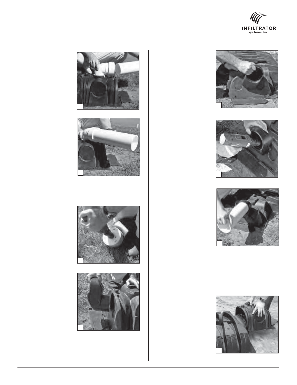
Installing Chambers and End Caps
1. To allow pressure laterals to drain after each dose, drill a hole
in the bottom of the pipe at the end of the pressure line. Place
the snap-off splash plate or a paving block at the bottom of the
trench to protect the infiltrative surface from erosion.
1" PRESSURE LATERAL (TYP.)
2" PRESSURE LATERAL (TYP.)
2. With a hole saw, drill out
the appropriate diameter
hole to accommodate the
pressure lateral pipe.
3. Insert the pressure lateral
pipe into the end cap’s drilled
opening and slide it into the
manifold pipe. Glue the
pressure lateral pipe to the
manifold pipe.
2
Drill pressure pipe hole.
Note: Health departments may
require a wet-run pressure check
to be done prior to chamber
installation when the pipe is laying on the ground. Check with
your local health department for
the proper procedure.
4
Place end cap over inlet end.
5. Secure the pressure lateral
pipe to the top of the first
chamber with a plastic pipe
strap at the outlet end of the
unit. Slide the strap up
through a slot in the chamber
top, down through the other
slot, and cinch the two ends
around the pipe.
6. Lift and place the next
chamber onto the previous
one at a 45-degree angle.
Line up the chamber end
5
Secure pressure pipe.
between the connector hook
and locking pin at the top of the first chamber. Lower it to the
ground to engage the interlocks.
7. Secure the lateral pipe to the top of the next chamber once in
place. Follow the same method in Step 5.
8. Continue interlocking chambers and securing the pipe until
the trench is completed.
9. Before attaching the final end cap, it may be necessary to
remove the tongue of the connector hook on the last chamber
with a pair of pliers depending on your pipe diameter.
10. Insert the pressure lateral
pipe through the hole in the
final end cap and slide the
end cap toward the last
chamber. Lift the end cap
over the modified connector
hook and push straight down
to secure it to the chamber.
Note: If cleanout extensions are
required, use a hole saw to cut a
hole in the top of the Quick4
Plus All-in-One Endcap so the
pressure lateral pipe with an
elbow can extend to the ground
surface. For cleanout access,
use the “Installing Optional
Inspection Ports” section in the
general installation instructions.
10
Lateral pipe through end cap.
ACCESS FOR DRAINFIELD MAINTENANCE AND FLUSHING
VALVE BOX
(OR IRRIGATION BOX)
4. With the pressure lateral pipe through the end cap, place the
back edge of the end cap over the inlet end of the first chamber.
Be sure to line up the locking pins on the top of both the
chamber and end cap.
Page 30 Contact Infiltrator Systems, Inc. 1-800-221-4436 for additional Minnesota technical and product information.
QUICK4 PLUS
STANDARD LP
Page 31

QUICK4 PLUS CHAMBERS INSTALLATION
Advantages of Method A
• Pipe and orifice placed closer to the chamber dome offer
improved distribution.
• Pipe positioned at the top of the chamber places it well
above effluent.
• Plastic pipe hanger easily secures pipe in place.
ALL WEATHER PLASTIC PIPE STRAP WITH
120 POUNDS TENSILE STRENGTH AT EVERY
CHAMBER CONNECTION
PRESSURE PIPE WITH HOLES AT 12 O’CLOCK
(MAY BE INSTALLED ON EITHER SIDE)
34"
QUICK4 PLUS
STANDARD LP CHAMBER
8"
Advantage of Method B
• Pipe resting on the trench bottom allows easy installation
and maintenance.
• Stabilizing “T’s” keep pipe level.
• System promotes efficient pressure checks.
• Pipe resting on the trench bottom allows easier inspections
if monitoring ports are installed.
STABILIZE OR "T" EVERY 10' TO
PREVENT PIPE ROTATION AND
PRESSURE PIPE WITH HOLES AT 12 O’CLOCK
(MAY BE INSTALLED ON EITHER SIDE)
34"
MAINTAIN PROPER PIPE POSITION
QUICK4 PLUS
STANDARD LP CHAMBER
8"
Contact Infiltrator Systems, Inc. 1-800-221-4436 for additional Minnesota technical and product information. Page 31
Page 32

One Year Standard Warranty
(a) The structural integrity of each chamber, end plate, wedge and other accessory manufactured by Infiltrator (collectively referred to as “Units”), when installed and operated in a leachfield of an
onsite septic system in accordance with Infiltrator's installation instructions, is warranted to the original purchaser (“Holder”) against defective materials and workmanship for one year from the date
upon which a septic permit is issued for the septic system containing the Units; provided, however, that if a septic permit is not required for the septic system by applicable law, the one (1) year warranty period will begin upon the date that installation of the septic system commences. In order to exercise its warranty rights, Holder must notify Infiltrator in writing at its corporate headquarters in
Old Saybrook, Connecticut within fifteen (15) days of the alleged defect. Infiltrator will supply replacement Units for those Units determined by Infiltrator to be defective and covered by this Limited
Warranty. Infiltrator’s liability specifically excludes the cost of removal and/or installation of the Units.
(b) THE LIMITED WARRANTY AND REMEDIES IN SUBPARAGRAPH (a) ARE EXCLUSIVE. THERE ARE NO OTHER WARRANTIES WITH RESPECT TO THE UNITS, INCLUDING NO IMPLIED
WARRANTIES OF MERCHANTABILITY OR FITNESS FOR A PARTICULAR PURPOSE.
(c) This Limited Warranty shall be void if any part of the chamber system (chamber, end plate, wedge or other accessory) is manufactured by anyone other than Infiltrator. The Limited Warranty does
not extend to incidental, consequential, special or indirect damages. Infiltrator shall not be liable for penalties or liquidated damages, including loss of production and profits, labor and materials,
overhead costs, or other losses or expenses incurred by the Holder or any third party. Specifically excluded from Limited Warranty coverage are damage to the Units due to ordinary wear and tear,
alteration, accident, misuse, abuse or neglect of the Units; the Units being subjected to vehicle traffic or other conditions which are not permitted by the installation instructions; failure to maintain the
minimum ground covers set forth in the installation instructions; the placement of improper materials into the system containing the Units; failure of the Units or the septic system due to improper
siting or improper sizing, excessive water usage, improper grease disposal, or improper operation; or any other event not caused by Infiltrator. This Limited Warranty shall be void if the Holder fails
to comply with all of the terms set forth in this Limited Warranty.
Further, in no event shall Infiltrator be responsible for any loss or damage to the Holder, the Units, or any third party resulting from installation or shipment, or from any product liability claims of Holder
or any third party. For this Limited Warranty to apply, the Units must be installed in accordance with all site conditions required by state and local codes; all other applicable laws; and Infiltrator’s
installation instructions.
(d) No representative of Infiltrator has the authority to change this Limited Warranty in any manner whatsoever, or to extend this Limited Warranty. No warranty applies to any party other than the
original Holder.
The above represents the standard Limited Warranty offered by Infiltrator. A limited number of states and counties have different warranty requirements. Any purchaser of Units should contact
Infiltrator's corporate headquarters in Old Saybrook, Connecticut, prior to such purchase, to obtain a copy of the applicable warranty, and should carefully read that warranty prior to the purchase of
Units.
* * * * * * *
Minnesota Five Year Warranty
(a) Warranty. Infiltrator Systems Inc. warrants that each chamber, end plate, wedge and other accessories manufactured by Infiltrator (collectively, the "Units"), when installed and operated in a leachfield of an on-site septic system in accordance with the written instructions of Infiltrator Systems Inc. at the time of installation, and in accordance with the Minnesota Chamber Sizing Chart, are warranted for a period of five (5) years from date of installation (i) to be free from defective materials and workmanship, and (ii) to perform in accordance with the state and local leachfield performance
requirements in effect on the date of installation. For this Warranty to apply, the Units must be installed in accordance with Infiltrator Systems Inc.'s written installation instructions ("Instructions") and
with applicable state and local laws and regulations applicable to sewage disposal systems. In the event of a conflict or inconsistency between the Instructions and such laws and regulations, the
Instructions shall take precedence over such laws and regulations, as permitted by Minnesota statute. The foregoing warranty is in lieu of all other warranties, expressed or implied, including but not
limited to implied warranties of merchantability and fitness for a particular purpose.
(b) Conditions Which Void Warranty. Infiltrator Systems Inc. does not warrant any Units not manufactured by Infiltrator Systems Inc. or for Infiltrator Systems Inc.; defects caused by failure to provide
a suitable installation environment for Units; failures to install the Units in accordance with Infiltrator Systems Inc.'s current written Instructions, damage resulting from improper sizing, excessive water
usage, improper grease disposal, or other improper use of the septic systems; damage resulting from improper siting of the septic system; damage arising from failure to maintain the septic tank in
accordance with the instructions of the tank manufacturer and Infiltrator Systems Inc.; damage caused by the Unit for purposes other than those for which it was designed; damage caused by abuse,
misuse, or neglect by Buyer or any other party; damage to any Unit which has been subject to conditions, pressures, or stresses more severe than or exceeding those set forth in Infiltrator Systems
Inc.'s written Instructions; damage caused by placement by Buyer or any other party of improper material into the Units; and damage from any other event not caused by Infiltrator Systems Inc. This
Warranty shall also be void if Buyer fails to comply with Section C of this Warranty.
(c) Processing A Claim; Determination Of Warranty Coverage. Should a defect or failure of performance appear in the Warranty period, Buyer must notify Infiltrator Systems Inc. in writing of the defect
or failure of performance within fifteen (15) days of discovery of the defect or failure of performance. Notice shall be in writing and sent by registered or certified mail to Infiltrator Systems Inc., 6
Business Park Road, P.O. Box 768, Old Saybrook, Connecticut 06475, attention Warranty Claims. The notice shall be accompanied by (i) a copy of the Infiltrator Warranty which is signed and dated
by Buyer and Installer, as set forth below, (ii) a copy of the appropriate permit for the septic system, and (iii) documentation to Infiltrator Systems Inc.'s satisfaction that the septic tank has been maintained in accordance with the instructions of the tank manufacturer and of Infiltrator Systems Inc. Infiltrator Systems Inc. will investigate the Warranty claim and will use its best efforts to notify Buyer
of its findings within thirty (30) days of receipt of the claim. At its option, Infiltrator Systems Inc. may perform tests to determine the cause of the failure. For claims which Infiltrator Systems Inc. determines are valid claims, Infiltrator Systems Inc. will pay the costs of redesign, if necessary, replacement Units, material, and labor costs for installing new Units, with the installation to be performed
by a contractor selected by Infiltrator Systems Inc. This paragraph states Buyer's sole remedy for defective Units and performance failures, and Infiltrator Systems Inc. shall have no responsibility or
liability for other items associated with the septic system.
(d) Original Installation Is Buyer's Responsibility. Buyer shall be solely responsible for ensuring that the original installation of the Units is completed in accordance with all applicable laws, codes,
rules, and regulations.
(e) Limitation Of Liability. In no case shall Infiltrator Systems Inc. be liable for incidental, consequential, indirect, or special damages based upon breach of warranty, breach of contract, negligence,
strict tort, or any other legal theory. Infiltrator Systems Inc. shall not be liable for any penalties or liquidated damages, including without limitation loss of production or profits, labor and materials
(except as provided in Section C), overhead costs, claims of third parties, injury to property, or other losses or expenses incurred by Buyer.
(f) Sole Warranty; No Changes Authorized. The Warranty described above is the sole warranty offered by Infiltrator Systems Inc. Infiltrator Systems Inc. does not assume any other liability in connection with the sale of the Units. No representative of Infiltrator Systems Inc. is allowed to extend this Warranty or to change it in any manner whatsoever.
P.O. Box 768 • 6 Business Park Road • Old Saybrook, CT 06475
860-577-7000 • FAX 860-577-7001
www.infiltratorsystems.com
1-800-221-4436
U.S. Patents: 4,759,661; 5,017,041; 5,156,488; 5,336,017; 5,401,116; 5,401,459; 5,511,903; 5,716,163; 5,588,778; 5,839,844 Canadian Patents: 1,329,959; 2,004,564 Other patents pending.
Infiltrator, Equalizer, and Quick4 are registered trademarks of Infiltrator Systems Inc. Infiltrator is a registered trademark in France. Infiltrator Systems Inc. is a registered trademark in Mexico.
ChamberSpacer, Contour, Contour Swivel Connection, MicroLeaching, MultiPort, PolyTuff, PosiLock, QuickCut, QuickPlay, SnapLock and Quick4 Plus are trademarks of Infiltrator Systems Inc.
© 2009 Infiltrator Systems Inc. All rights reserved. Printed in U.S.A.
C991009ISI-0
 Loading...