

Infanor SMT-BD1/m User Manual

SMT-BD1/m
gb
SMT-BD1/m
Positioner
INFRANOR®
SMT-BD1/m
1

SMT-BD1/m
2 SMT-BD1/m

SMT-BD1/m
!
WARNING !
This is a general manual describing a series of servo amplifiers having output capability suitable for driving AC
brushless sinusoidal servo motors. This manual may be used in conjunction with appropriate and referenced
drawings pertaining to the various specific models.
Maintenance procedures should be attempted only by highly skilled technicians having good knowledge
of electronics and servo systems with variable speed (EN 60 204.1 standard) and using proper test
equipment.
The conformity with the standards and the "CE" approval are only valid if the items are installed according to the
recommendations of the amplifiers manuals. Connections are the user's responsibility if recommendations and
drawings requirements are not met.
Any contact with electrical parts, even after power down, may involve physical damage.
Wait for at least 5 minutes after power down before handling the amplifiers (a residual voltage of several hundreds
of volts may remain during a few minutes).
INFRANOR drives are conceived to be best protected against electrostatic discharges. However, some
components are particularly sensitive and may be damaged. Before handling the drives and, particularly, before
any contact with the connectors, the user himself must be earthed. Place or store the drives on conducting or
electrostatically neutral areas but not on plastic areas, carpeting or insulation material that may be electrostatically
loaded.
INFRANOR does not assume any responsibility for any physical or material damage due to improper handling or
wrong descriptions of the ordered items.
Any intervention on the items, which is not specified in the manual, will immediately cancel the warranty.
Infranor reserves the right to change any information contained in this manual without notice.
This manual is a translation of the original document and does not commit INFRANOR's responsibility. The french
manual is the only reference document.
©INFRANOR, March 2005. All rights reserved
Issue: 5.0
SMT-BD1/m
3

SMT-BD1/m
4 SMT-BD1/m

SMT-BD1/m
Contents
PAGE
CONTENTS.............................................................................................................................................................5
CHAPTER 1 - GENERAL DESCRIPTION...............................................................................................................7
1 - INTRODUCTION.............................................................................................................................................7
2
- GENERAL DESCRIPTION ..............................................................................................................................7
3
- COMPLIANCE WITH THE STANDARDS ........................................................................................................7
4
- OTHER DOCUMENTS TO BE USED OR THE DRIVE COMMISSIONING......................................................7
CHAPTER 2 - SPECIFICATIONS............................................................................................................................8
- MAIN TECHNICAL DATA ................................................................................................................................8
1
1.1 - Current ratings 220 VAC drive version .....................................................................................................8
1.2 - Current ratings for 400 VAC drive version ................................................................................................9
1.3 - Other specifications ................................................................................................................................10
- MAIN PROTECTIONS...................................................................................................................................11
2
2.1 - STORED PROTECTIONS......................................................................................................................11
2.2 - FUSE PROTECTION OF THE SMT-BD1/M DRIVE VERSION 220 VAC...............................................11
2.3 - FUSE PROTECTION OF THE SMT-BD1/M DRIVE VERSION 400 VAC...............................................12
CHAPTER 3 - INPUTS-OUTPUTS........................................................................................................................13
- CONNECTORS.............................................................................................................................................13
1
1.1 - Rack connectors.....................................................................................................................................13
1.2 - Drive connectors.....................................................................................................................................13
- X1: RESOLVER CONNECTOR.....................................................................................................................14
2
3
- X2: ENCODER CONNECTOR.......................................................................................................................14
4
- X4: COMMAND CONNECTOR - SUB D 25 PINS MALE.....................................................................................15
5
- X6: LOGIC OUTPUTS CONNECTOR - SUB D 9 PINS FEMALE ........................................................................15
6
- X7: LOGIC INPUTS CONNECTOR - SUB D 9 PINS MALE................................................................................15
7
- X5: RS-232 CONNECTOR - SUB D 9 PINS MALE..............................................................................................16
8
- X3: TEST CONNECTOR ...............................................................................................................................16
9
- SPECIFICATIONS OF THE LOGIC INPUTS-OUTPUTS...............................................................................16
9.1 - DEDICATED LOGIC INPUTS: FC+, FC-, INDEX, RUN AND ENABLE..................................................16
9.2 - LOGIC INPUTS START, STOP, JOG+, JOG-, IN1 TO IN8....................................................................16
9.3 - LOGIC OUTPUTS SEQ, POS, SPEED, OK, OUT1 TO OUT8...............................................................17
CHAPTER 4 - CONNECTIONS.............................................................................................................................18
- CONNECTION DIAGRAMS...........................................................................................................................18
1
1.1 - POWER SUPPLY AND MOTOR CONNECTIONS.................................................................................18
1.2 - SERIAL LINK CONNECTION.................................................................................................................18
- WIRING RECOMMENDATIONS ...................................................................................................................18
2
2.1 - GND WIRING AND GROUNDING .........................................................................................................18
2.2 - SHIELD CONNECTION ON THE CONNECTORS.................................................................................19
2.3 - MOTOR AND RESOLVER CABLES ......................................................................................................20
2.4 - SERIAL LINK CABLE .............................................................................................................................20
- FIRST POWERING OF THE DRIVE..............................................................................................................20
3
CHAPTER 5 - FUNCTIONAL FEATURES ............................................................................................................21
- DESCRIPTION OF THE LOGIC INPUTS-OUTPUTS ....................................................................................21
1
1.1 - LOGIC INPUTS ......................................................................................................................................21
1.2 - LOGIC OUTPUTS ..................................................................................................................................22
- ADDRESSING...............................................................................................................................................22
2
3
- REDUCTION OF THE PROGRAMMED SPEED VIA AN ANALOG INPUT....................................................22
CHAPTER 6 - COMMISSIONING..........................................................................................................................24
- CHECKING THE DRIVE CONFIGURATION .................................................................................................24
1
2
- INSTALLING THE PC SOFTWARE...............................................................................................................24
2.1 - Basic configuration .................................................................................................................................24
2.2 - Installation ..............................................................................................................................................24
2.3 - Connection to a drive and start of the software ......................................................................................24
- PUTTING INTO OPERATION .......................................................................................................................25
3
Contents
5

SMT-BD1/m
4
- DRIVE COMMISSIONING AND ADJUSTMENT............................................................................................25
4.1 - PARAMETER SETTING OF MOTOR AND DRIVE................................................................................26
4.2 - MOTOR / DRIVE PARAMETER SETTING WITH A VERTICAL LOAD..................................................26
4.3 - SAVING THE DRIVE PARAMETERS ....................................................................................................27
4.4 - ENABLING .............................................................................................................................................30
4.5 - MANUAL MOVE.....................................................................................................................................31
- PROGRAMMATION......................................................................................................................................32
5
5.1 - GENERAL DESCRIPTION.....................................................................................................................32
5.2 - EDITION OF A SEQUENCE...................................................................................................................33
- PROGRAMME EXECUTION.........................................................................................................................36
6
7
- USE OF THE OSCILLOSCOPE.....................................................................................................................36
CHAPTER 7 - TROUBLESHOOTING AND MAINTENANCE ...............................................................................38
- SYSTEM ERROR..........................................................................................................................................38
1
2
- STORED ERRORS .......................................................................................................................................38
2.1 - "BUSY" ...................................................................................................................................................38
2.2 - "NovRAM" or "EEPROM"........................................................................................................................38
2.3 - "°C MOTOR"...........................................................................................................................................38
2.4 - "UNDERVOLT".......................................................................................................................................39
2.5 -"°C AMPLIFIER"......................................................................................................................................39
2.6 - "POWER STAGE" ..................................................................................................................................39
2.7 - "RESOLVER"..........................................................................................................................................39
2.8 - "R.D.C" ...................................................................................................................................................39
2
T" ........................................................................................................................................................39
2.9 - "I
- OPERATION PROBLEMS.............................................................................................................................40
3
3.1 - NO MOTOR MOVEMENT ......................................................................................................................40
3.2 - MOTOR SUPPLIED BUT NO TORQUE.................................................................................................40
3.3 - SHAFT LOCKED, ERRATIC OSCILLATIONS OR ROTATION AT MAXIMUM SPEED.........................40
3.4 - DISCONTINUOUS MOTOR ROTATION WITH ZERO TORQUE POSITIONS......................................40
3.5 - LOUD CRACKLING NOISE IN THE MOTOR AT STANDSTILL ............................................................40
3.6 - LOUD NOISE IN THE MOTOR AT STANDSTILL AND WHEN RUNNING ............................................40
- SERVICE AND MAINTENANCE....................................................................................................................40
4
CHAPTER 8 - APPENDIX .....................................................................................................................................41
- USING SMT-BD1/M WITH A DISPLAY TERMINAL........................................................................................41
1
1.1 - CONFIGURATION .................................................................................................................................41
1.2 - USE ........................................................................................................................................................41
- SMT-BD1/M INSTRUCTIONS LIST ...............................................................................................................43
2
2.1 - OVERVIEW ............................................................................................................................................43
2.2 - INSTRUCTIONS LIST ............................................................................................................................44
- HARDWARE ADJUSTMENTS LOCATION ...................................................................................................48
3
4
- ADJUSTMENT TO VARIOUS RESOLVERS .................................................................................................51
5
- ADJUSTMENT TO THE MOTOR...................................................................................................................52
5.1 - CONFIGURATION OF THE MOTOR THERMAL SENSOR...................................................................52
5.1.1 - THERMAL SENSOR PTC ...................................................................................................................52
5.1.2 - THERMAL SENSOR NTC...................................................................................................................52
- CURRENT LOOPS.....................................................................................................................................52
5.2
5.2.1 - CURRENT LOOPS ADJUSTMENT ON DRIVES WITH 400 VAC SUPPLY........................................52
5.3 - I2t PROTECTION....................................................................................................................................53
- LOGIC CONTROL ADJUSTMENT ................................................................................................................56
6
6.1 - POSITIVE OR NEGATIVE LOGIC INPUTS ...........................................................................................56
6.2 - USE OF THE "AMP. READY" AND "POWER READY" OUTPUTS........................................................56
- SERIAL LINK.................................................................................................................................................57
7
8
- DRIVE TYPES...............................................................................................................................................58
6
Contents

SMT-BD1/m
Chapter 1 - General description
1 - INTRODUCTION
Series SMT-BD1/m servo modules are PWM servo drives that provide speed control for AC sinusoidal motors
(brushless) with transmitter resolver.
The SMT-BD1/m positioner is available with two different mains supplies: 220 VAC or 400 VAC.
The plug-in positioner in 220 VAC is available either as a single-axis block version or as a multiaxis version that
can receive up to six axes in a standard 19" rack.
Both versions are including a power supply unit.
The plug-in positioner in 400 VAC is only available as a multiaxis version that can receive up to three axes in a
standard 19" rack including a power supply unit.
2 - GENERAL DESCRIPTION
The SMT-BD1/m servo modules have their own DC/DC converter to provide appropriate logic voltage to the
modules (+5 V / +/-15 V). The supply used for the logic board is the 310 V
saving of the position signal when the power supply is off.
Each module is packaged as two 6U "double Eurocard":
- one power board with IGBT transistors and
- one logic board with DSP (Digital Signal Processing).
The SMT-BD1/m positioner can operate as a stand-alone system or in connection with a PLC or a PC.
It can execute up to 128 motion sequences. The sequences can generate position, speed or torque motions.
The SMT-BD1/m positioner generates itself the positioning trajectory by waiting for the START signal or for a
command via the serial link for starting the programme.
3 - COMPLIANCE WITH THE STANDARDS
Series SMT-BD1/m positioners with 220 VAC supply and operating in the BF rack equipped with the mains filter
BF 35 or 70, have been approved with regard to their conformity with the Electromagnetic Compatibility standards:
- EN 55011, group 1, class A, regarding the conducted and radiated radioelectric disturbances,
- CEI 801 - 2 - 3 - 4 regarding immunity.
The SMT-BD1/m positioners with 220 VAC supply, operating in the single-axis racks BM20A - BMM05F BMM05AF equipped with the pertaining mains filter (FN 612-20/06 or FN 356-16/06 or BF-35) have been
approved with regard to their conformity with the Electromagnetic Compatibility standards
- EN 55011, group 1, class A, regarding the conducted and radiated radioelectric disturbances,
- CEI 801 - 2 - 3 - 4 regarding immunity.
Series SMT-BD1/m positioners with 400 VAC supply and operating in the BF rack equipped with the mains filter
BF 400-35 or 400-70, have been approved with regard to their conformity with the Electromagnetic Compatibility
standards
- EN 55011, group 1, class A, regarding the conducted and radiated radioelectric disturbances,
- CEI 801 - 2 - 3 - 4 regarding immunity.
Standard to be applied to the electrical equipment of industrial machines: EN 60204-1.
Series SMT-BD1 drives have been CE marked since 1995.
4 - OTHER DOCUMENTS TO BE USED OR THE DRIVE COMMISSIONING
BF/400 rack – for the use of 400 VAC drives in multi-axis racks.
BF rack – for the use of 220 VAC drives in multi-axis racks.
BM20A / BMM05F / BMM05AF racks – for the use of 220 VAC drives in single-axis racks.
auxiliary supply which allows the
DC
Chapter 1 - General description
7
SMT-BD1/m
Chapter 2 - Specifications
1 - MAIN TECHNICAL DATA
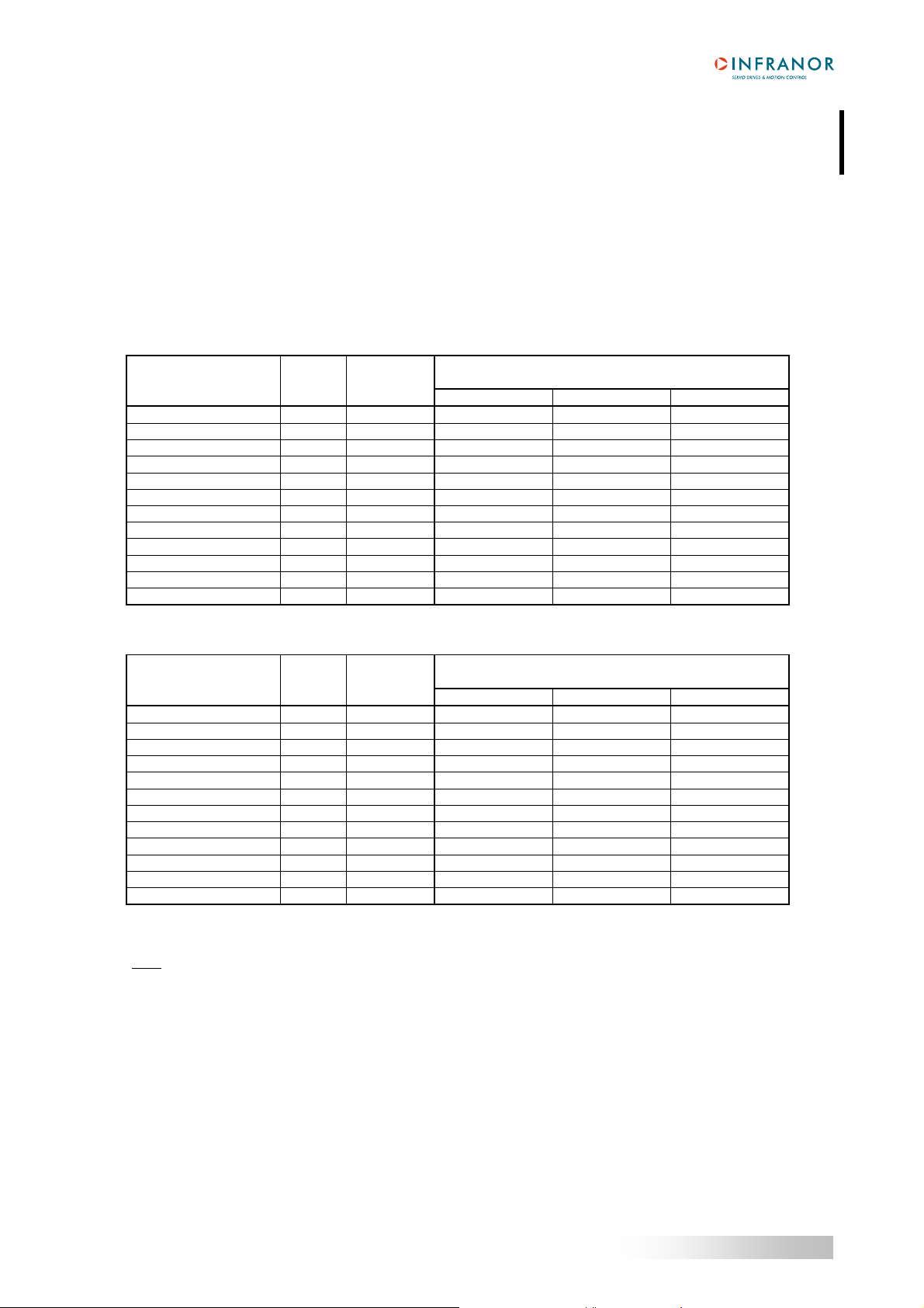
1.1 - Current ratings 220 VAC drive version
Operating voltage 310 V
Auxiliary supply voltage 310 V
Motor phase-phase output voltage 200 Vrms for 310 V
Output current ratings in pulse current mode (I
DRIVE
TYPE
1 s No fan* Fan 1* Fan 2*
SMT-BD1/m-220/04 240 4.4 2
SMT-BD1/m -220/08 240 8.8 4
SMT-BD1/m-220/12 240 13.8 6
SMT-BD1/m-220/17 240 17.7 8.5
SMT-BD1/m-220/30 240 30.8 10 12 15
SMT-BD1/m-220/30r 240 30.8 10 15
SMT-BD1/m-220/45 240 48.6 10 15 20
SMT-BD1/m-220/45r 240 48.6 10 20 23
SMT-BD1/m-220/60 240 61 10 19 25
SMT-BD1/m-220/60r 240 61 12 26 30
SMT-BD1/m-220/70 240 70 25 30 35
SMT-BD1/m-220/100 240 100 25 30 35
Output current ratings in pulse current mode (I2t protection in "limiting" mode)
DRIVE
TYPE
1 s No fan* Fan 1* Fan 2*
SMT-BD1/m-220/04 240 4,4 2
SMT-BD1/m -220/08 240 8.8 4
SMT-BD1/m-220/12 240 13.8 6
SMT-BD1/m-220/17 240 17.7 8.5 8.5
SMT-BD1/m-220/30 240 30.8 8.5 12 15
SMT-BD1/m-220/30r 240 30.8 10 15
SMT-BD1/m-220/45 240 48.6 8.5 15 18
SMT-BD1/m-220/45r 240 48.6 10 20 23
SMT-BD1/m-220/60 240 61 8.5 17 20
SMT-BD1/m-220/60r 240 61 12 26 30
SMT-BD1/m-220/70 240 70 17 30 35
SMT-BD1/m-220/100 240 100 25 30 35
* Maximum ambient temperature = 40° C, fan 1 = 56 l/s, fan 2 = 90 l/s.
Note
: SMT-BD1-X/X r drive types are equipped with an additional heatsink in order to improve the heat dissipation
and increase their rated current. The width of these drives is then 18 TE instead of 12 TE.
Minimum inductance between phases 1 mH
Urated
(Vrms)
Urated
(Vrms)
Imax (Arms) Max. authorized rated current (Arms)
Imax (Arms) Max. authorized rated current (Arms)
2
t protection in "fusing" mode)
DC (270 VDC < DC bus < 340 VDC)
DC (200 VDC < Uaux < 340 VDC)
DC bus
of the drive
of the drive
8
Chapter 2 - Specifications
SMT-BD1/m
Compliance with the standards: CE approval for - EMC standards
multi-axis operation in the BF rack with mains Immunity: CEI standards 801- 2 - 3 - 4
filter BF35 or 70 or in single-axis racks BM20A or Conducted and radiated disturbances: EN 55011,
BMM05F/05AF with filters FN 612-20/06 or Group 1, class A
FN 356-16/06 or BF-35. 360° shield and - Electrical standards for industrial machines:
equipotential according to the wiring rules EN 60204.1: - Insulator: 1500 VAC/1 min.
- Leakage current > 3 mA
(EMI filters)
Temperature * storage - 20°C to + 70°C
* operation 5°C to +40°C
From 40°C on, the rated currents must be reduced
of 3 %/°C.
Max. temperature: 50°C
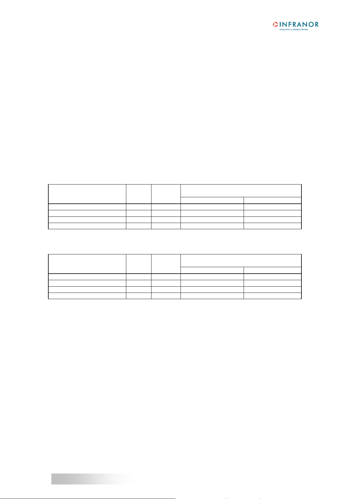
1.2 - Current ratings for 400 VAC drive version
Operating voltage 565 V
Auxiliary supply voltage 310 V
Motor phase-phase output voltage 380 Vrms for 565 V
Output current ratings in pulse current mode (I
2
t protection in "fusing" mode)
DC (480 VDC < DC bus < max. 685 VDC)
DC (200 VDC < Uaux < 340 VDC)
DC bus
DRIVE
TYPE
Urated
(Vrms)
Imax
(Arms)
Max. authorized rated current (Arms)
of the drive
1 s No fan* Fan 2*
SMT-BD1/m-400/15 400 15.5 5 7.5
SMT-BD1/m-400/30 400 30 8 15
SMT-BD1/m-400/45 400 48 10 19
SMT-BD1/m-400/60 400 60 not used 28
Output current ratings in pulse current mode (I
2
t protection in "limiting" mode)
DRIVE
TYPE
Urated
(Vrms)
Imax
(Arms)
Max. authorized rated current (Arms)
of the drive
1 s No fan* Fan 2*
SMT-BD1/m-400/15 400 15.5 not used 5
SMT-BD1/m-400/30 400 30 not used 10
SMT-BD1/m-400/45 400 48 not used 15
SMT-BD1/m-400/60 400 60 not used 23
Maximum room temperature: 40°C, fan type 2: 90 l/s.
Minimum inductance between phases 2 mH
Compliance with the standards: CE approval for - EMC standards
multi-axis operation in the BF rack with mains Immunity: CEI standards 801- 2 - 3 - 4
filter BF-400/35 or 400/70. Conducted and radiated disturbances: EN 55011,
360° shield and equipotential according to the Group 1, class A
wiring rules. - Electrical standards for industrial machines:
EN 60204.1: - Insulator: 2500 VAC/1 min.
- Leakage current > 3 mA
(EMI filters)
Temperature * storage - 20°C to + 70°C
* operation 5°C to +40°C
From 40°C on, the rated currents must be reduced
of 3 %/°C.
Max. temperature: 50°C
Chapter 2 - Specifications
9

SMT-BD1/m
1.3 - Other specifications
PWM switching frequency 10 kHz
Current regulator (PI) adjusted to motor
Current loop bandwidth Cut-off frequency for 45° phase shift > 1 kHz
Internal current limitation Imax: 20 % to 100 % and I rated: 20 % to 50 %
Imax duration =1 second
Speed and position regulators Sampling period = 0,5 ms
Anti-wind-up system of the integrator
Adjustable digital gains
Speed loop bandwidth Selectable cut-off frequency for 45° phase shift:
50 Hz, 75 Hz or 100 Hz
Max motor speed Adjustable from 100 rpm to 10 000 rpm
Encoder position output Two A and B channels in quadradure + n zero pulses per
revolution. Programmable resolution:
max. 8 192 ppr up to 900 rpm
max. 4 096 ppr up to 3 600 rpm
max.1 024 ppr up to 10 000 rpm
Accuracy: 8 arc minutes +1/4 point
(optional: 2 arc minutes + 1/4 point)
Note
accuracy of the resolver used
Analog outputs (test connector) Speed input command (CV): ±10 V for ± max speed.
Speed monitor (GT): ±8 V for ±14 000 rpm, linearity: 10%
Current input command (Idc): ±10 V for ± current rating,
resolution: 8 bits
Current monitor (Imes): ±10 V for ± current rating;
resolution: 8 bits
Logic inputs Enable/Disable: ENABLE
Limit switch +: FC+
Limit switch - : FC-
Homing input: INDEX
Error reset: RAZ
Optocoupled logic inputs START, STOP, JOG+, JOG-, IN1 to IN8
Relay outputs Relay contact: Umax = 60 V
Imax = 200 mA, Pmax = 10 W
"Amp. ready": closed if drive OK, open if error
"Power ready": closed if power OK, open if error
Brake control
Optocoupled logic outputs SEQ, POS, SPEED, OK, OUT1 to OUT8
Error display Front panel LEDs and diagnostic via serial link RS-232
Motor and application parameter setting Serial link RS-232
Automatic functions Drive adjustment to the motor (AUTO-PHASING)
Automatic regulator tuning (AUTO-TUNING)
Altitude 1000 m
: The total position accuracy must take into account the
10
Chapter 2 - Specifications

SMT-BD1/m
Moisture < 50% at 40°C and < 90% at 20°C: EN 60204-1 standard
Condensation prohibited
Cooling Natural convection or forced air according to the rated
current. Condensation prohibited.
2 - MAIN PROTECTIONS
2.1 - STORED PROTECTIONS
PROTECTION ERROR DISPLAY LED
Drive rated current overload *:
- blinking display = Idyn warning (I
- continuous display = drive disabled (I
Position following error Position
2
t threshold reached)
2
t error)
2
I
t
z
z
Resolver cable interruption Resolver
Power stage error:
- power supply overvoltage
- internal switch protection
- short-circuit between phases
- drive overtemperature for 4 A to 60 A current ratings
Resolver converter error R.D.C
Drive overtemperature for 70 A and 100 A current ratings °C Ampli
Power supply undervoltage Undervoltage
Motor overtemperature °C Motor
Drive parameter memory error NovRAM
Automatic procedure of the drive
- blinking display = procedure running
- continuous display = operating error
Power stage
Busy
z
z z
z
z
z
z
z
z z
z
z
z z
z z
z z
: Led is unlit z : Led is lit
* The operation mode of the I2t protection is described in chapter 8, section 5. 3.
All these errors are stored in the drive, except for the "Undervoltage" error.
The reset of a stored error can be made:
- via the error RESET input of X4, pin 13,
- by switching off the drive power supply.
2.2 - FUSE PROTECTION OF THE SMT-BD1/M DRIVE VERSION 220 VAC
F1 : Control of the average DC current of the power board supply.
F2 : Control of the average DC current of the logic board supply.
DRIVE TYPE F1 - POWER F2 - LOGIC
SMT-BD1/m-220/04 to 12 10 AT 1 A
SMT-BD1/m-220/17 and 30 15 AT 1 A
SMT-BD1/m-220/45 20 AT 1 A
SMT-BD1/m-220/60 20 AT 1 A
SMT-BD1/m-220/70 - 1 A
SMT-BD1/m-220/100 - 1 A
Chapter 2 - Specifications
11

SMT-BD1/m
2.3 - FUSE PROTECTION OF THE SMT-BD1/M DRIVE VERSION 400 VAC
F2 : Control of the average DC current of the logic board supply.
DRIVE TYPE F2 - LOGIC
SMT-BD1/m-400/15 1 A
SMT-BD1/m-400/30 1 A
SMT-BD1/m-400/45 1 A
SMT-BD1/m-400/60 1 A
12
Chapter 2 - Specifications
SMT-BD1/m
Chapter 3 - Inputs-Outputs
1 - CONNECTORS
1.1 - Rack connectors
For the 400 VAC drive version, see manual BF/400 RACK.
For the 220 VAC drive version, see manuals SMT-BM20A SINGLE-AXIS RACK or BF RACK.
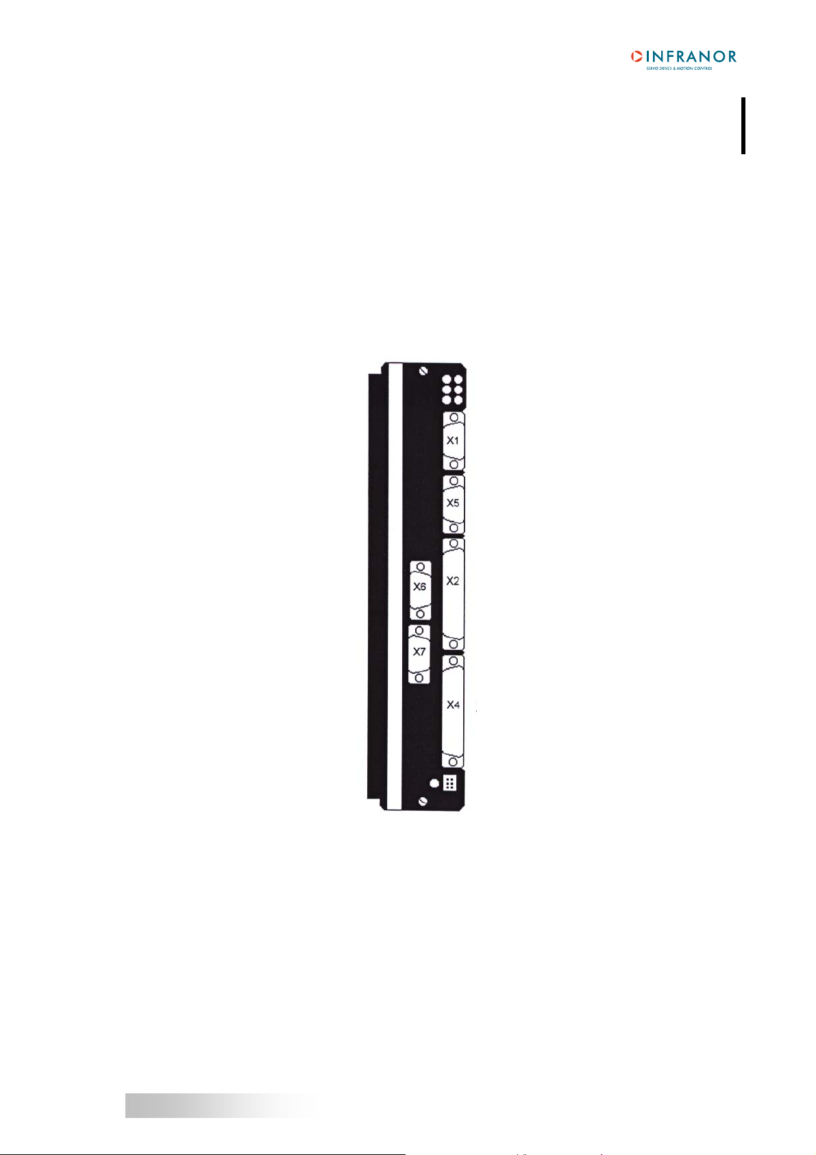
1.2 - Drive connectors
Front panel connectors
X1 Resolver
X5 Serial link RS-232
X6 Programmable
logic outputs
X7 Logic inputs
X2 Encoder
X4 Command
X3 Test
Chapter 3 - Inputs-Outputs
13

SMT-BD1/m
2 - X1: RESOLVER CONNECTOR
Sub D 9 pins female.
PIN FUNCTION REMARKS
1 TC (pin H sensor connector) If thermal switch connected to X1
6 Shield connection If no "360°" connection on the connector
2 TC (pin I sensor connector) If thermal switch connected to X1
7 S1 (pin C sensor connector) MAVILOR motor
3 S3 (pin D sensor connector) MAVILOR motor
8 S4 (pin B sensor connector) MAVILOR motor
4 S2 (pin A sensor connector) MAVILOR motor
9 R2 (pin F sensor connector) MAVILOR motor
5 R1 (pin E sensor connector) MAVILOR motor
For the connection of other resolvers than the resolver used on MAVILOR motors, see Chapter 8, section 4.
3 - X2: ENCODER CONNECTOR
Sub D 25 pins female
PIN SIGNAL I/O DESCRIPTION
1 /CZ O Differential output of the encoder marker pulse (5 V 20 mA max.)
2 CZ O Differential output of the encoder marker pulse
3 /CA O Differential output of the encoder channel A (5 V 20 mA max.)
4 CA O Differential output of the encoder channel A
5 /CB O Differential output of the encoder channel B (5 V 20 mA max.)
6 CB O Differential output of the encoder channel B
7, 10, 11 0 V
14 START I Optocoupled logic input
15 STOP I Optocoupled logic input
16 WAIT I Optocoupled logic input
17 TEACH I Optocoupled logic input
24 5 V 5 V jumper must be closed
8 JOG+ I Optocoupled logic input
18 JOG- I Optocoupled logic input
9 SEQ O Optocoupled logic output
20 POS O Optocoupled logic output
21 SPEED O Optocoupled logic output
22 OK O Optocoupled logic output
23 GND (24 V) Mass of external 24 V
12 24 V I 24 V input. This input must be used only if one of the outputs SEQ,
SPEED, POS and OK is used and if the OUT1 to OUT8 outputs are not
wired.
25 GND
14
Chapter 3 – Inputs-Outputs

SMT-BD1/m
4 - X4: COMMAND CONNECTOR - Sub D 25 pins male
PIN FUNCTION I/O REMARKS
1 Limit switch + I Positive or negative logic
14 Limit switch - I Positive or negative logic
24 0V limit switch I
20 ENABLE I Positive or negative logic
23 0 Volt ENABLE I
4 RUN I Positive or negative logic
7 INDEX/CLR I Positive or negative logic
25 0 V logic input
13 RESET I Error RESET via 0 volt (contact between pins 13 and 12)
12 0V RESET I
15 Reserved
16 0 V analog I
17 Analog input I Speed reduction option
3 Reserved
10 Speed monitor GT O
2 Current monitor Imes (DAC OUT2) O
11 0 Volt analog output O
18, 19 Amp. ready O Relay contact, closed when drive OK
Pmax = 10 W with Umax = 60 V or Imax = 200 mA
8, 9 Brake control output O Relay contact.
Pmax = 10 W with Umax = 60 V or Imax = 200 mA
21 +15 Volts O Max. 50 mA
22 -15 Volts O Max. 50 mA
5, 6 Unconnected
5 - X6: LOGIC OUTPUTS CONNECTOR - Sub D 9 pins female
PIN SIGNAL DESCRIPTION
1 OUT1 Programmable output n° 1
2 OUT2 Programmable output n° 2
3 OUT3 Programmable output n° 3
4 OUT4 Programmable output n° 4
5 OUT5 Programmable output n° 5
6 OUT6 Programmable output n° 6
7 OUT7 Programmable output n° 7
8 OUT8 Programmable output n° 8
9 24 V This 24 V must be used if one of the OUT1 to OUT8
outputs is wired
6 - X7: LOGIC INPUTS CONNECTOR - Sub D 9 pins male
PIN SIGNAL DESCRIPTION
1 IN1 Logic input n° 1
2 IN2 Logic input n° 2
3 IN3 Logic input n° 3
4 IN4 Logic input n° 4
5 IN5 Logic input n° 5
6 IN6 Logic input n° 6
7 IN7 Logic input n° 7
8 IN8 Logic input n° 8
9 GND 24 V Mass of external 24 V
Chapter 3 - Inputs-Outputs
15
SMT-BD1/m
7 - X5: RS-232 CONNECTOR - Sub D 9 pins male
PIN FUNCTION REMARKS
5 0 V GND (shield connection if no "360°" connection on the connector)
3 TXD Transmit data RS 232
2 RXD Receive data RS 232
6 TXH Transmit data RS 422
7 TXL Transmit data RS 422
8 RXL Receive data RS 422
9 RXH Receive data RS 422
8 - X3: TEST CONNECTOR
PIN FUNCTION REMARKS
1 - 6 0 Volt
2 Current input command IDC ± 10 V; resolution: 8 bits, linearity: 10 % (DAC out 1)*
3 Reversed analog input ± 10 V for ± max. speed
4 Speed monitor GT ± 8 V for ± 14000 rpm
5 Current monitor I
* : 10 V for drive current rating.
± 10 V; resolution: 8 bits, linearity: 10 % (DAC out 2)*
mes
9 - SPECIFICATIONS OF THE LOGIC INPUTS-OUTPUTS
9.1 - DEDICATED LOGIC INPUTS: FC+, FC-, INDEX, RUN AND ENABLE
Input impedance : 4,7 kΩ
Response time : 500 µs
These inputs can be configurated in positive or negative logic by means of jumpers (see chapter 8, section
6.1 "Positive or negative logic inputs")
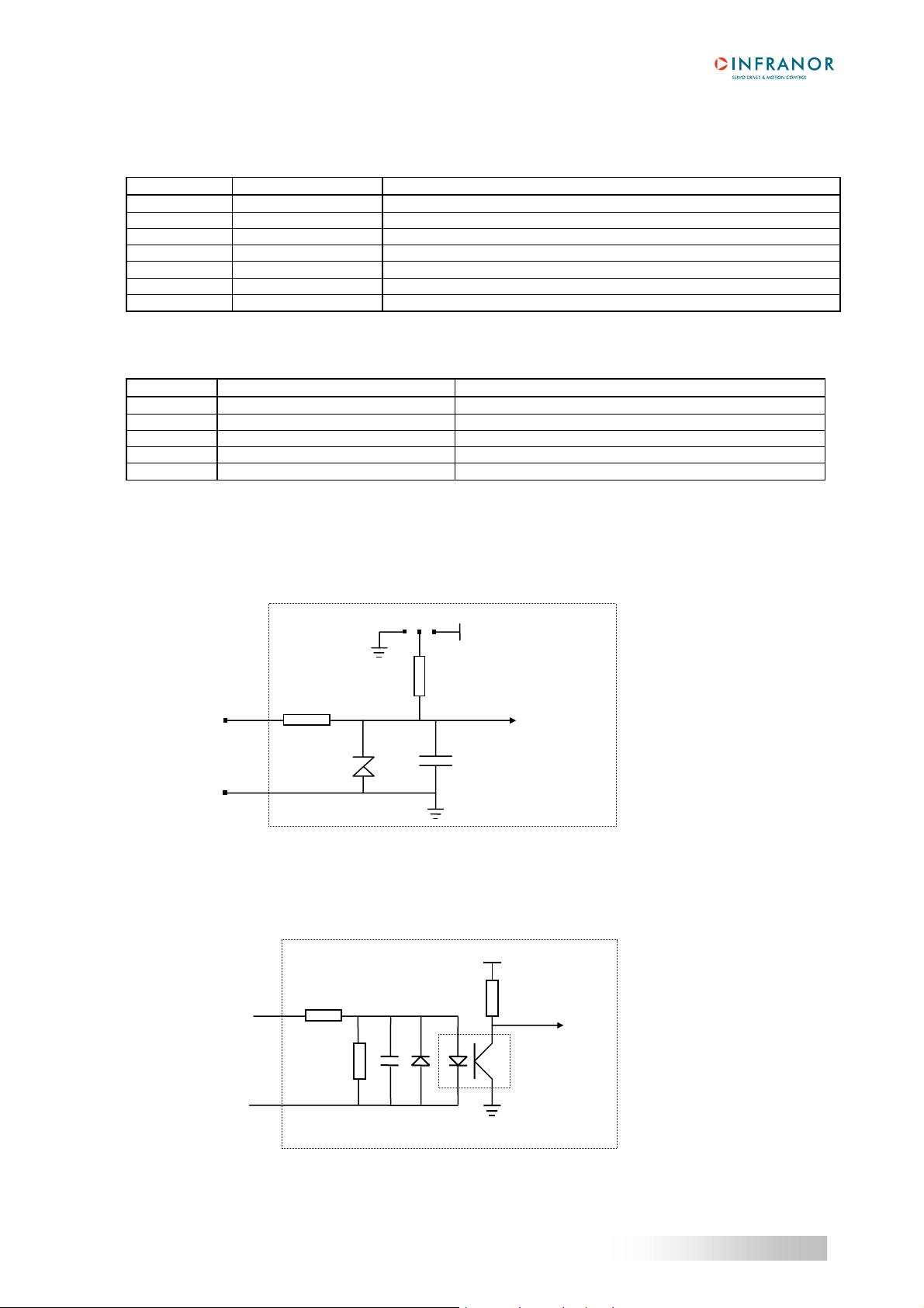
9.2 - LOGIC INPUTS START, STOP, JOG+, JOG-, IN1 TO IN8
The input voltage corresponds
Logic input
to level 1 and is between 5 V
and 24 V
The polarity of these inputs can be reversed by a software parameter (see chapter 6, section 4.3.1 "Inputs -
outputs configuration").
0 V
4,7 KΩ
4,7 V
2.2 KΩ
100 KΩ 100 nF
Log Log -
47 KΩ
5 V
47 nF
5 V
SMT-BD1/m
SMT-BD1/m
PC829
16
Chapter 3 – Inputs-Outputs

SMT-BD1/m
9.3 - LOGIC OUTPUTS SEQ, POS, SPEED, OK, OUT1 TO OUT8
The output current is
350 mA for the 8 outputs
OUT1 to OUT8.
The polarity of these inputs can be reversed by a software parameter (see chapter 6, section 4.3.1 "Inputs -
outputs configuration").
The parallel connection of these outputs must be made by means of diods.
IMPORTANT NOTE
If the 24 V is available when the drive is off, the logic SEQ, POS, SPEED, OK, OUT1 to OUT8 are set at
24 V.
24 V
Logic output
UDN2987A
0 V
SMT-BD1/m
5 V
PC829
Chapter 3 - Inputs-Outputs
17
SMT-BD1/m
Chapter 4 - Connections
1 - CONNECTION DIAGRAMS
1.1 - POWER SUPPLY AND MOTOR CONNECTIONS
For the 400 VAC drive, see manual BF/400 Rack.
For the 220 VAC drive, see manuals BF Rack or SMT-BM20 A / BMM05F/AF single-axis racks.
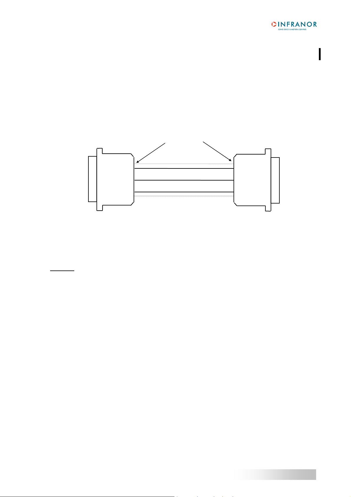
1.2 - SERIAL LINK CONNECTION
Serial port
PC
Sub D 9pts female
RxD 2
TxD 3
GND 5
2 - WIRING RECOMMENDATIONS
(according to standards CEI 801 and EN55011 - see diagram "Shield connection on the connectors" –
Chapter 4, section 2.2).
2.1 - GND WIRING AND GROUNDING
CAUTION
Each potential conducting element MUST be shielded. Several wires in the same sleeve must be twisted and
shielded.
A shield has no effect if it is not connected:
- to a reference potential,
- via a connection as short as possible (some centimeters; 10 cm is prohibited),
- by a "360°" shield connection, that means that the whole circumference of the shield sleeve must be
According to the CEI 801 standard, connectors must be made of metal or metal plated and must allow a 360°
shield connection.
Long reference potential connections (especially with the ground) are suitable ONLY if these connections have a
very low impedance (less than 0,1 Ω). Any shield that is not used as a conductor can be connected at both ends if
it is connected at both ends over 360° by means of metal connections ensuring the shield continuity.
The reference potential is the ground.
Cables with low potential should NEVER run in the proximity of power lines.
If there is a potential reference, like a main chassis or a cabinet with a low impedance between its various
elements, it should be used for short connections and be grounded itself.
!
connected to the reference conductor by a metal collar.
360° shield connection
3 TxD
2 RxD
5 GND
Sub D 9pts female
SMT-BD1/m
X5
18
Chapter 4 – Connections
 Loading...