

iNetVu PowerSmart 2480 Operating Manual
iNetVu® PowerSmart 2480
Operating Manual
The iNetVu® brand and logo are registered trademarks of C-COM Satellite Systems, Inc.
© Copyright 2006 C-COM Satellite Systems, Inc.
1-877-iNetVu6
www.c-comsat.com
Revision 011
June 2, 2015

2
TABLE OF CONTENTS
1. Introduction................................................................................................................................................. 3
2. Specifications ............................................................................................................................................. 4
3. Physical ...................................................................................................................................................... 5
3.1. Front Panel (2480 Version 1.0+) .............................................................................................................. 5
3.2. Front Panel (2480 Version 2.0+) .............................................................................................................. 7
3.3. Back Panel (Both versions 1.0 & 2.0+) .................................................................................................... 8
4. Typical Connection Configuration ............................................................................................................. 10
Option 2: PowerSmart 2480 with Integrated BUC Connectivity (Separate AC/DC Power and M&C cables) 12
Option 3: PowerSmart 2480 with BIAS-T Thruplexer (DC Powered through M&C and 10MHz from Bias T)
........................................................................................................................................................................... 13
Option 4: PowerSmart 2480 with BIAS-T Thruplexer (DC Powered through coax + No M&C) ................... 14
Option 5: External AC/DC Powered BUC with No M&C ............................................................................... 15
Option 6: PowerSmart 2480 with BIAS-T Thruplexer (DC Powered through coax + M&C) ......................... 16
Option 7: PowerSmart 2480 with Integrated BUC Connectivity (Separate AC/DC Power and M&C cables) 17
5. Installation ................................................................................................................................................ 18
5.1. Rack Installation ..................................................................................................................................... 18
5.2. Setup and Operation ............................................................................................................................... 18
APPENDIX A – Powersmart 2480 with MATCHBOX WAVESTREAM BUC ..................................................... 19
Powersmart PC Software Interface Device ....................................................................................................... 19
Powersmart 2480 Switch Definitions for Matchbox Wavestream supported BUCs ........................................ 22
APPENDIX B – Powersmart 2480 with AnaCom Baby ELSAT BUC ................................................................ 23
Powersmart PC Software Interface Device ....................................................................................................... 23
PowerSmart 2480 Switch Definitions for AnaCom Baby ELSAT supported BUCs ....................................... 24
APPENDIX C – Powersmart 2480 with CODAN LBUC .................................................................................... 25
Powersmart PC Software Interface Device ....................................................................................................... 25
Powersmart 2480 Switch Definitions for Codan supported LBUCs ................................................................ 26
APPENDIX D – Powersmart 2480 with AGILIS 80W BUC – Model ALB190ACH-80J-1 .................................. 27
Powersmart PC Software Interface Device(s) .................................................................................................. 27
Powersmart 2480 Switch Definitions for AGILIS 80W supported BUCs ....................................................... 29
APPENDIX E – Powersmart 2480 with AGILIS ALB-128 and ALB-129/229 Series BUC ................................. 32
Powersmart PC Software Interface Device(s) .................................................................................................. 33
Powersmart 2480 Switch Definitions for AGILIS 8W/16W/40W supported BUC(S) .................................... 41
APPENDIX F – Powersmart 2480 Version 2.0+ with AGILIS ALB-128 and ALB-129/229 Series BUC ............ 43
Powersmart PC Software Interface Device(s) .................................................................................................. 44
APPENDIX F – Powersmart 2480 with AGILIS ALB 190AF7-40B BUC (INT C-BAND 40W) ........................... 51
Powersmart PC Software Interface Device(s) .................................................................................................. 52
Powersmart 2480 Switch Definitions for AGILIS 40W supported BUC(S) .................................................... 60
APPENDIX F – Powersmart 2480 Version 2.0+ with AGILIS ALB 190AF7-40B BUC (INT C-BAND 40W) ...... 62
Powersmart PC Software Interface Device(s) .................................................................................................. 63

3
1. Introduction
The iNetVu® PowerSmart 2480 is ideal for applications where a VSAT Transmitter/Amplifier requires more
power than a Satellite Modem can provide over the TX output. This is typical for larger Block Up
Converters (BUC) or Power Amplifiers (SSPA, etc) that supply over 8 Watts RF output power.
The PowerSmart 2480 has been designed to provide 24/48VDC or 110/220 VAC power to external
amplifiers, and includes features to support Monitor and Control (M&C) functions for several products.*
Most AC/DC powered BUCs and SSPAs, and TWAs can be integrated with the PowerSmart 2480, for an
efficient and convenient hardware solution to provide POWER plus M&C Control to an outdoor transmitter
unit. Optional features can be added such as Bias-T, DC Blocker, MUX-T with 10 MHz Clock, all in a
convenient rack mount enclosure.
Amplifier functions such as TX Enable/Disable and operational status can be monitored and controlled from
a convenient operation control panel. Also, configuration parameters, onboard statistics, and fault
information can be accessed via the amplifier’s control interface (if available) through a convenient data
port on the panel. The amplifier manufacturer’s software can typically be operated from a PC platform
through the configurable port, over RS232, RS485, or SNMP interface as required.
Enabling the Transmit function, monitoring BUC faults and the presence of 10MHz reference on the IFL,
verifying output power level, and other common functions along with the rack mount format make the
PowerSmart 2480 a value-added solution to higher-powered VSAT applications.
*NOTE - Monitor and Control functions are dependent on the VSAT Transmitter/Amplifier
manufacturer's design. The primary feature of the iNetVu PowerSmart product is to provide power
to the transmitter from a convenient rack mounted indoor unit. All iNetVu PowerSmart front panel
features may not be functional with all models of transmitters. Typically, a communications feature
is available that may also require other manufacturer's hardware and software to run on a userprovided computer platform.

POWER SUPPLY
P2480A
P2480B
P2480C
OUTPUT
Voltage
48 VDC
24 VDC (optional)
110/220 VAC
Rated Power
480W
*See AC Current
INPUT
Voltage Range
85 ~ 264 VAC
Frequency Range
47 ~ 63Hz
AC Current
6.5A/115VAC
3.5A/230VAC
ENVIRONMENTAL
Working Temp
-20° ~ +60° C
Storage Temp.,
Humidity
-40° ~ +85° C, 10 ~ 95% RH
PHYSICAL
Dimensions
482.602 x 361.703 x 43.5 (W x L x H) mm
Max Weight
14 lbs
AMPLIFIER
INTERFACE
RS-232
BUC/AMP Dependent – P2480 Adaptable/Configurable
RS-485
BUC/AMP Dependent – P2480 Adaptable/Configurable
SNMP
BUC/AMP Dependent – P2480 Adaptable/Configurable
PC INTERFACE
DB9 on front panel used to access amplifier Software via PC
FRONT PANEL
SWITCHES
POWER
Powers ON/OFF the BUC
TRANSMIT
Enables/Disables the Transmit
FRONT PANEL
LED INDICATIONS
(M&C FUNCTION
DEPENDENT)
TRANSMIT LED
LED will turn ON or OFF indicating transmit status
Lock Loss LED
This LED is lit when the up converter losses lock indicating the 10 MHz
reference on the IFL is not present, the signal level is too low or is frequency
unstable.
Over Temp LED
Unit temperature has exceeded its internal cutoff. Power to the internal
amplifier module is cut off automatically if the internal temperature reaches
a point where the amplifier might be damaged.
Sum Fault LED
This LED is lit when there is a critical fault with the internal amplifier
COMPATIBILITY
*Supports most AC/DC Power Amplifiers
BIAS-T Thruplexer
(Optional)
C-COM Standard
L-Band and 10 MHz pass (not generated)
C-COM MUX-T
Provides 10 MHz Reference Generation Capability
L-Band pass, plus 10 MHz Clock, plus DC/DC Block
CERTIFICATIONS
FCC
CE
QPS
2. Specifications
4
Note* the iNetVu PowerSmart 2480 could be easily customized to integrate with many AC/DC powered BUC Models. Not
all front panel LED’s are functional with some BUC’s. Specifications subject to change without notice

Jumpers Added
enables Serial to
RS485/RJ45
3. Physical
3.1. Front Panel (2480 Version 1.0+)
Fig. 1: iNetVu® PowerSmart 2480 version 1.0 Front Panel
1. DB9 (RS232/RS485/RJ45) PC Interface
A PC could be used to run the software for Monitor and Control of the Integrated Wavestream
Matchbox, Anacom, Codan L and Agilis BUCs. Currently this port supports RS232 and RS485
serial communication.
Adding jumpers on both connectors will enable RS485/RJ45 on DB9.
5
No jumper on both connectors will enable RS232 on DB9.

Transmit LED
ON indicates BUC is transmitting
OFF indicates BUC is not transmitting
Lock Loss LED
This LED is lit when the up converter losses lock indicating the 10 MHz
reference on the IFL is not present, the signal level is too low or is frequency
unstable.
Over Temp LED
Unit temperature has exceeded its internal cutoff. Power to the internal amplifier
module is cut off automatically if the internal temperature reaches a point
where the amplifier might be damaged.
Sum Fault LED
This LED is lit when there is a critical fault with the internal amplifier
Jumpers removed
enable Serial to
RS232
DB9F Connector Pin RS232 Signal (jumpers removed) RS485 (jumpers in) RJ45 (jumpers in)
1 Not Used Not Used **See Appendix for details
2 TD RDA(-)
3 RD TDB(+)
4 Not Used Gnd
5 Gnd Not Used
6 Not Used Gnd
7 Not Used RDB(+)
8 Not Used TDA(-)
9 Not Used Not used
Ensure the PC Serial Interface or cable matches the pins/signals on the PowerSmart front panel DB9
Female connector for software M&C control. See Appendix for the recommended device with the
integrated BUC’s.
2. BUC Status LED’s *
6
*may not be functional for some integrated BUC’s – See Appendix
3. TX ENABLE/DISABLE SWITCH
The TX ENABLE/DISABLE switch supplies external transmit control for supporting high powered BUC’s
with M&C capabilities.
4. POWER SWITCH
The power switch supplies AC/DC power to the BUC.

3.2. Front Panel (2480 Version 2.0+)
Fig. 2: iNetVu® PowerSmart 2480 version 2.0+ Front Panel
Note: The front panel has 2 Interface options, a USB or ETHERNET connection. Only
one of these can be selected when ordering your PowerSmart, depending on your BUC
Monitor & Control interface requirements.
1. MONITOR & CONTROL INTERFACE
There are 2 interfaces (USB and Ethernet) that are available which allows the operator to customize
their preferred communication method. USB is used and internally coverts to RS485 serial. Ethernet is
passed through to the BUC.
2. POWER SWITCH
The power switch supplies AC/DC power to the BUC.
7
8
5
4 3 2
1
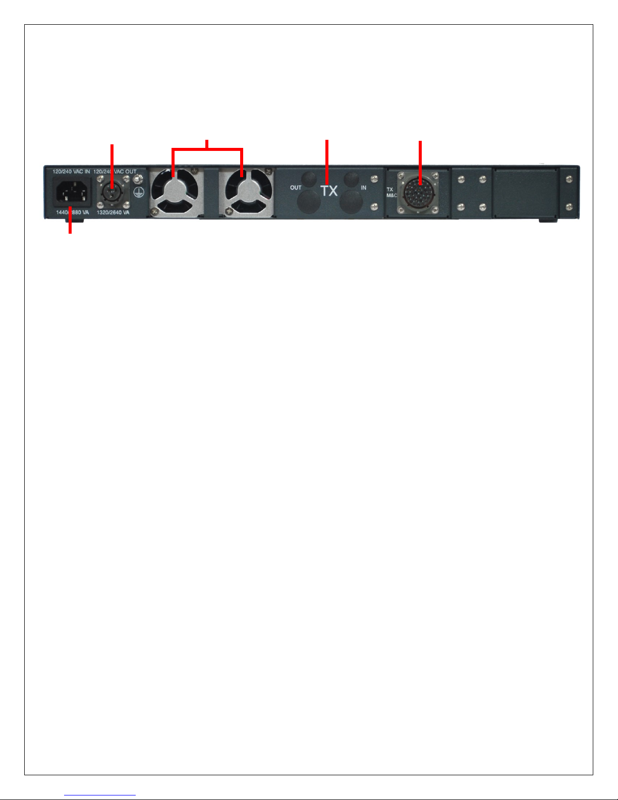
3.3. Back Panel (Both versions 1.0 & 2.0+)
Fig. 3: iNetVu® PowerSmart 2480 Back Panel
The base model is strictly a power supply with an AC Input (no.1) and a Fan Assembly
(no. 3) without the additional components (no. 2, 4 and 5) depicted in the caption above.
The additional components may be added as options depending on the required/desired
configuration of the VSAT system.
1. AC Input
The powersmart 2480 will take AC input ranging from 85 ~ 264 VAC.
2. AC/DC Out
The powersmart has provided the capability of providing AC/DC output from the Power OUT port
(AC Out, no. 2 label on the back plate of the powersmart). AC power will be passed from the AC
input to the output port, and DC power could be generated from the internal power supply
depending on the users required configuration.
3. Fan Assembly
4. Bias-T Thruplexer (Available in F-type or N-type)
There are two optional types of the Bias-T Thruplexers currently available with the iNetVu
Powersmart 2480. The C-COM Standard Bias-T comes with L-Band and 10 MHz pass from a
modulating source. The C-COM MUX-T Thruplexer generates 10MHz reference capability
along with L-Band pass. The MUX-T also comes equipped with an internal switch that allows
for complete DC/DC Block on the coax cable allowing for an external M&C or Power Supply for
the amplifiers.
TX OUT
Bias-T Thruplexer output to amplifier.

TX IN
Bias-T Thruplexer input from modem.
5. M&C Cable port
Provides monitor and control capabilities for supporting amplifiers such as transmit control, and
monitoring capabilities.
9

10
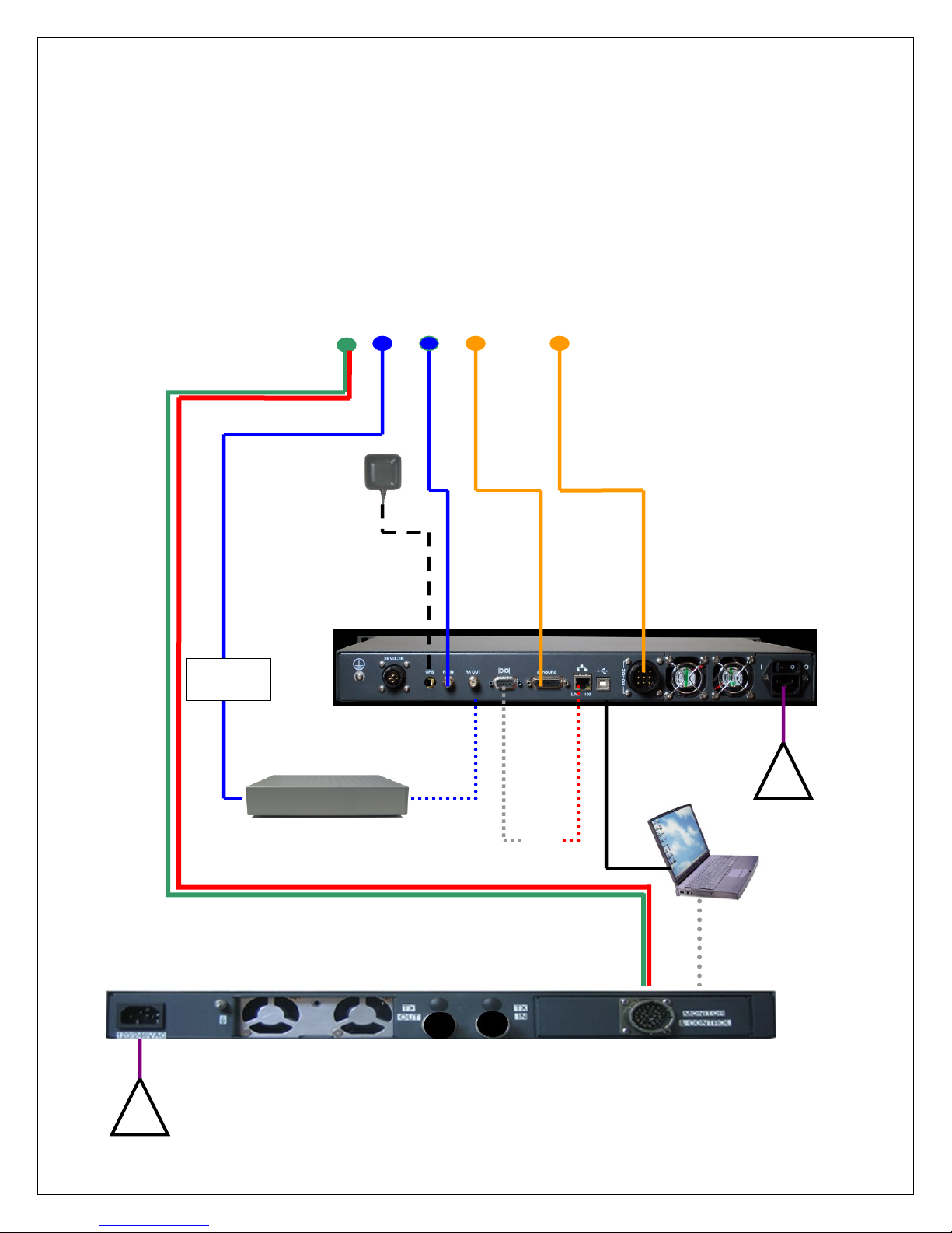
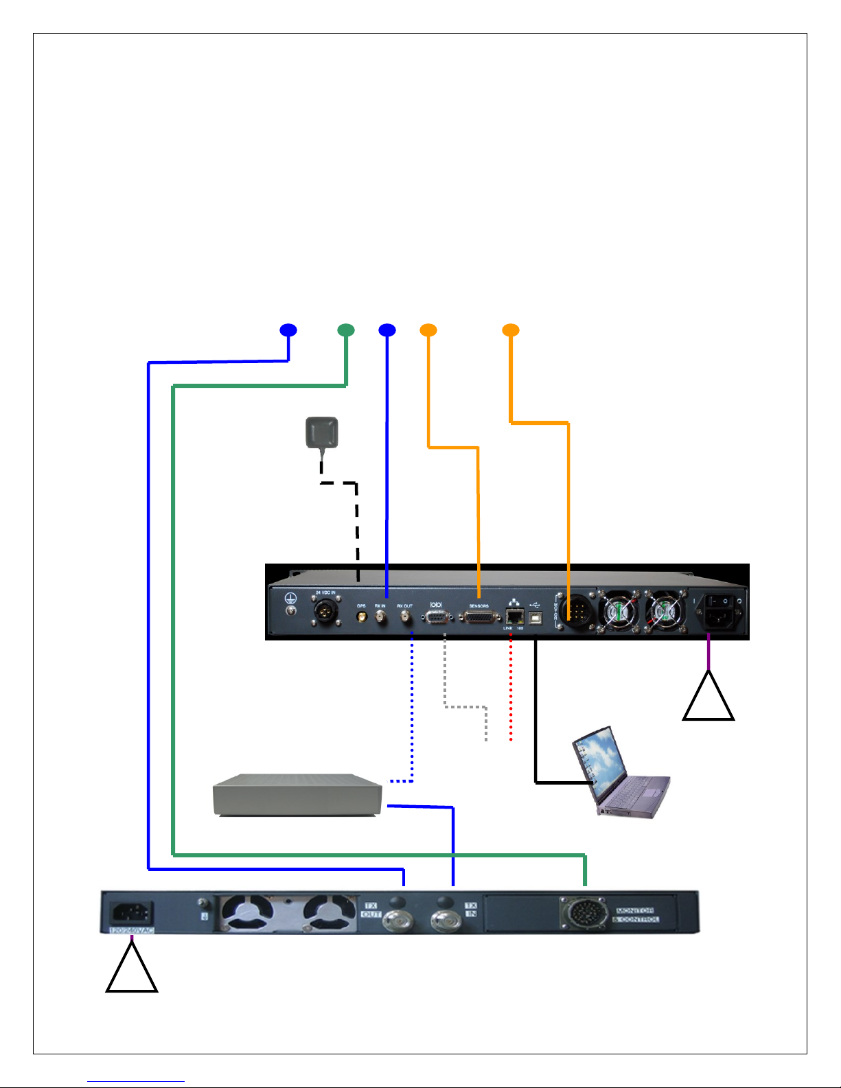
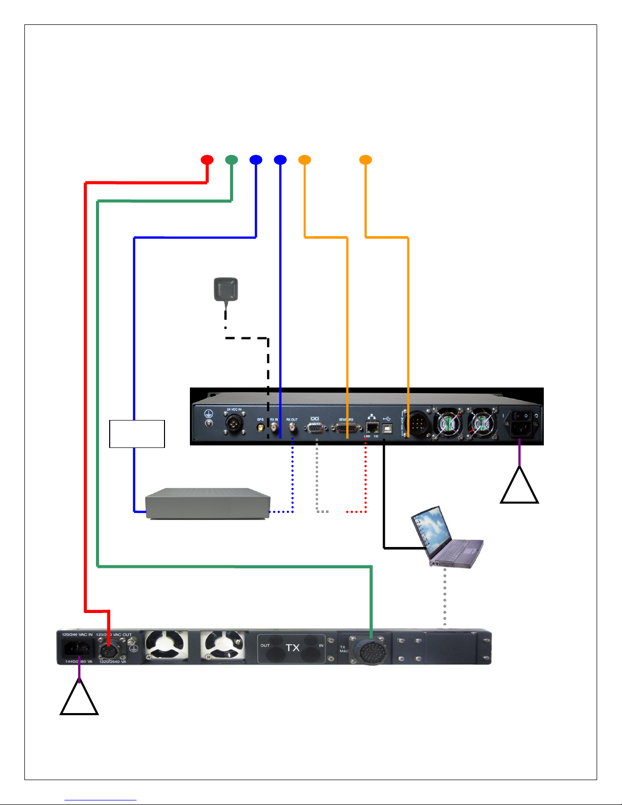
4. Typical Connection Configuration
The typical connection configuration for each service will be the same regardless of
the Satellite Modem / VSAT. However, the configuration parameters for Satellite
Modem / VSAT Communication will differ depending on service.
CAUTION: Verify the Correct Power Source Output
To prevent damage to the BUC, ensure that the proper voltage range and polarity is
selected prior to application of input power. Unit is powered either via the military circular
connector or via the IFL. Power must be applied to the proper connector depending on
Unit configuration.
Eg: The Part Number on the Wavestream BUC Unit identifies the proper voltage, for
example:
M B B – K U S 0 2 5 – D S 0 0
Where,
C = 24VDC / D = 48VDC / J = 48VDC on IFL / K = 24VDC on IFL
*This Part No. identifies Unit as requiring a 48VDC Prime.
Verify the correct polarity and voltage range are coming out of the PowerSmart 2480
prior to connecting to the BUC. Ensure the BUC requirements correspond to the
power supply output.
11
!
100 - 260VAC
RX IN
RX
TX
TX OUT
RX OUT
SAT IN
(if app.)
See
Note *
Note *: Network and Serial Port of Controller could be used to communicate with
integrated modems/beacon receiver and/or viewing controller interface via web browser or
software application. See corresponding VSAT based user manual for details on network
connectivity
Optional PC
Software Front
Panel DB9 Interface
Connection – See
Appendix for details
depending on
Integrated BUC
USB Cable
(Optional for
Controller M&C)
BUC M&C AND
POWER CABLE
WARNING: ENSURE TX POWER IS TURNED OFF IN THE MODEM PRIOR TO CONNECTING
THE TX CABLE IF POSSIBLE. DC BLOCK SHOULD BE USED ON THE TX COAX.
RECOMMENDED IN-SERIES DC BLOCK:
*Aeroflex/Inmet Model 8174
This is an in-series F, 75ohm, inner-conductor model rated to 200VDC and to
10MHz-2GHz passing.
NO DC POWER
PASS IN TX
COAX – DC
BLOCKED
GPS
/Glonass
ANTENNA
DC
BLOCK*
!
MOTOR
AND
SENSOR
CABLES
Disclaimer: The front panel LED’s may
not work for some BUC’s.
100 - 260VAC
Option 1: PowerSmart 2480 with Integrated BUC Connectivity (DC Powered
through M&C)
12
!
Modulator/Demodulator
RX IN
RX
TX
TX OUT
RX OUT
SAT IN
(if app.)
See
Note *
Note *: Network Port and Serial Port of Controller could be used to communicate with
integrated modems/beacon receiver and/or viewing controller interface via web browser or
software application. See corresponding VSAT based configuration manual for details on
network connectivity
Optional PC
Software Front
Panel DB9 Interface
Connection – See
Appendix for details
depending on
Integrated BUC
USB Cable
(Optional for
Controller M&C)
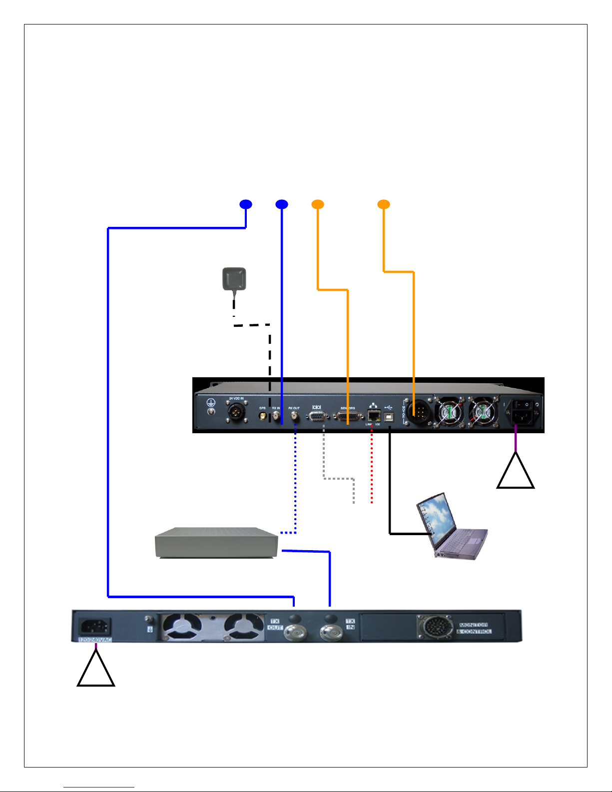
BUC M&C Cable
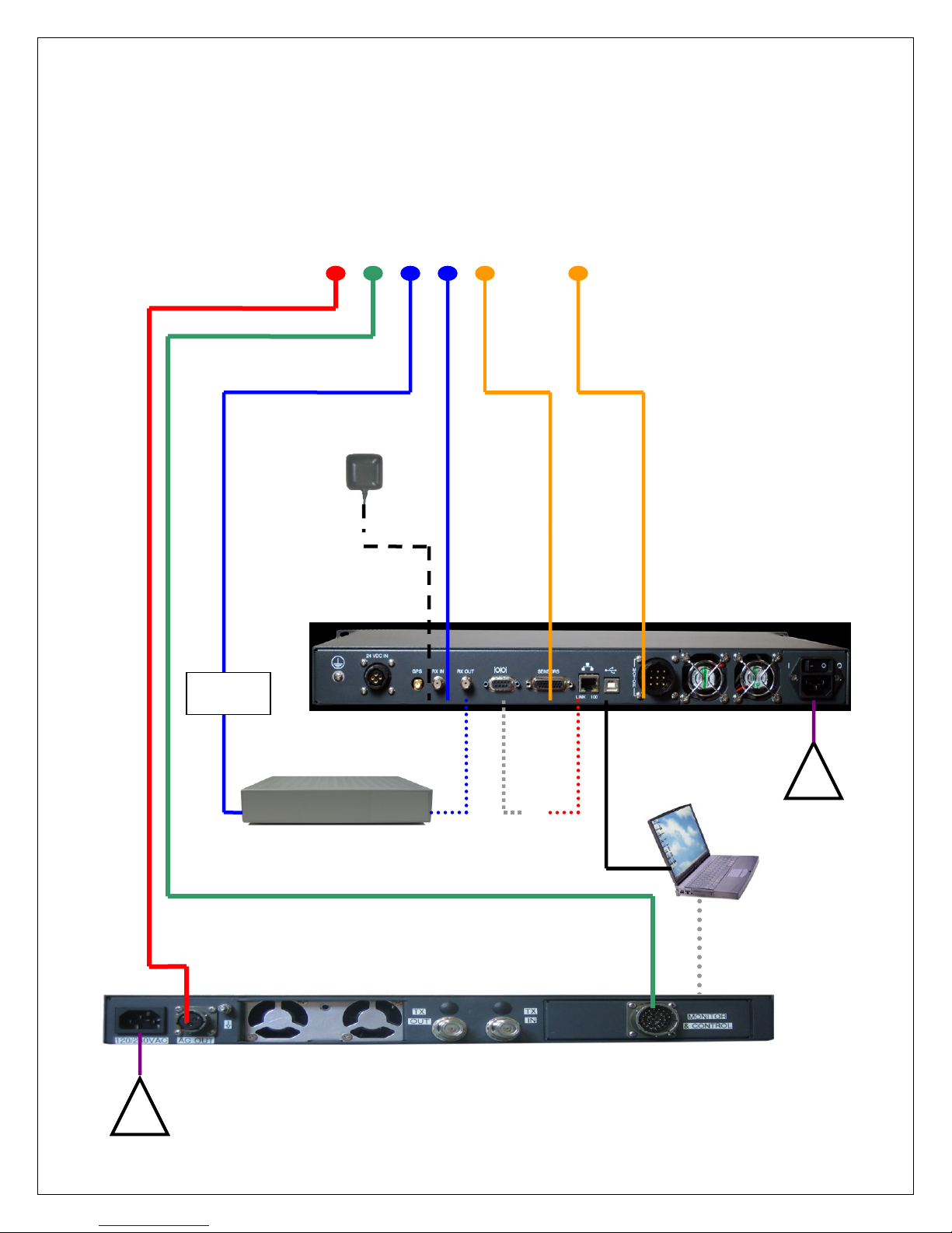
WARNING: IF OPTIONAL BIAS-T IS INSTALLED IN POWERSMART ENNSURE TX POWER
IS TURNED OFF IN THE MODEM PRIOR TO CONNECTING THE TX CABLE IF POSSIBLE.
DC BLOCK SHOULD BE USED ON THE TX COAX. RECOMMENDED IN-SERIES DC BLOCK:
*Aeroflex/Inmet Model 8174
This is an in-series F, 75ohm, inner-conductor model rated to 200VDC and to
10MHz-2GHz passing.
NO DC POWER
PASS IN TX
COAX – DC
BLOCKED
GPS/GLONASS
ANTENNA
DC
BLOCK*
!
BUC AC/DC Power Cable
MOTOR
AND
SENSOR
CABLES
100 - 260VAC
Disclaimer: The front panel LED’s may
not work for some BUC’s.
100 - 260VAC
Option 2: PowerSmart 2480 with Integrated BUC Connectivity (Separate AC/DC
Power and M&C cables)
13
!
100 - 260VAC
Modulator/Demodulator
RX IN
RX
TX
RX OUT
SAT IN
(if app.)
See Note *
Note *: Network and Serial Port of Controller could be used to communicate with integrated
modems/beacon receivers and/or viewing controller interface via web browser or software
application. See corresponding VSAT based cabling and configuration manual for details on
network connectivity
USB Cable
(Optional for
Controller M&C
Software)
GPS/GLONASS
ANTENNA
WARNING: ENSURE TX POWER IS TURNED OFF IN THE MODEM PRIOR TO CONNECTING THE TX CABLE IF
POSSIBLE. DC BLOCK SHOULD BE USED ON THE TX COAX FROM THE MODEM IF THE BUC IS POWERED FROM
THE EXTERNAL POWER SUPPLY AND BIAS TEE DOES NOT PROVIDE DC BLOCK ON MODEM CONNECTION.
SAT
OUT)
!
100 - 260VAC
TX IN
TX OUT
BUC M&C Cable
MOTOR
AND
SENSOR
CABLES
Disclaimer: The front panel LED’s may
not work for some BUC’s.
Option 3: PowerSmart 2480 with BIAS-T Thruplexer (DC Powered through M&C
and 10MHz from Bias T)
14
!
100 - 260VAC
Modulator/Demodulator
RX IN
RX
TX
RX OUT
SAT IN
(if app.)
See Note *
Note *: Network and Serial Port of Controller could be used to communicate with integrated
modems/beacon receivers and/or viewing controller interface via web browser or software
application. See corresponding VSAT based cabling and configuration manual for details on
network connectivity
USB Cable
(Optional for
Controller M&C
Software)
GPS/GLONASS
ANTENNA
WARNING: ENSURE TX POWER IS TURNED OFF IN THE MODEM PRIOR TO CONNECTING THE
TX CABLE IF POSSIBLE. DC BLOCK SHOULD BE USED ON THE TX COAX FROM THE MODEM IF
THE BUC IS POWERED FROM THE EXTERNAL POWER SUPPLY AND BIAS TEE DOES NOT
PROVIDE DC BLOCK ON MODEM CONNECTION.
SAT
OUT)
!
100 - 260VAC
TX IN
TX OUT
MOTOR
AND
SENSOR
CABLES
Disclaimer: The front panel LED’s may
not work for some BUC’s.
Option 4: PowerSmart 2480 with BIAS-T Thruplexer (DC Powered through coax
+ No M&C)
15
!
100 - 260VAC
Modulator/Demodulator
RX IN
RX
TX
TX OUT
RX OUT
SAT IN
(if app.)
See
Note *
Note *: Network Port and Serial Port of Controller could be used to communicate with
integrated modems/beacon receiver and/or viewing controller interface via web browser or
software application. See corresponding VSAT based configuration manual for details on
network connectivity
Optional PC
Software Front
Panel DB9 Interface
Connection – See
Appendix for details
depending on
Integrated BUC
USB Cable
(Optional for
Controller M&C)
NO DC POWER
PASS IN TX
COAX – DC
BLOCKED
GPS/GLONASS
ANTENNA
DC
BLOCK*
!
BUC AC/DC Power
MOTOR
AND
SENSOR
CABLES
100 - 260VAC
WARNING: ENSURE TX POWER IS TURNED OFF IN THE MODEM PRIOR TO CONNECTING THE TX
CABLE IF POSSIBLE. DC BLOCK SHOULD BE USED ON THE TX COAX. RECOMMENDED IN-SERIES DC
BLOCK:
*Aeroflex/Inmet Model 8174
This is an in-series F, 75ohm, inner-conductor model rated to 200VDC and to 10MHz-2GHz
passing.
Disclaimer: The front panel LED’s may
not work for some BUC’s.
Option 5: External AC/DC Powered BUC with No M&C
16
Computer
!
100 - 260VAC
Modulator/Demodulator
RX IN
RX
TX
RX OUT
SAT IN
(if app.)
See Note *
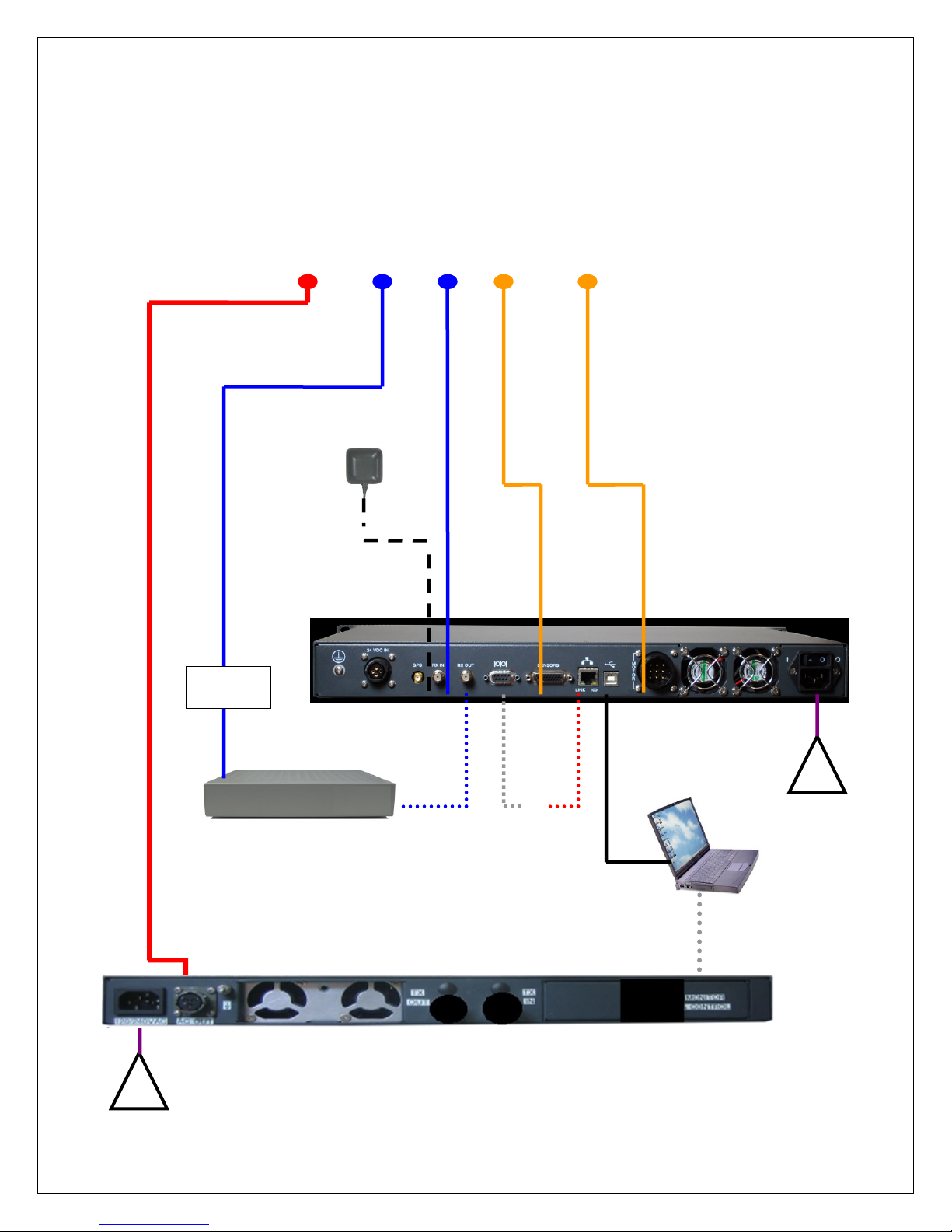
Note *: Network and Serial Port of Controller could be used to communicate with integrated
modems/beacon receivers and/or viewing controller interface via web browser or software
application. See corresponding VSAT based cabling and configuration manual for details on
network connectivity
USB Cable
(Optional for
Controller M&C
Software)
GPS/GLONASS
ANTENNA
WARNING: ENSURE TX POWER IS TURNED OFF IN THE MODEM PRIOR TO CONNECTING THE
TX CABLE IF POSSIBLE. DC BLOCK SHOULD BE USED ON THE TX COAX FROM THE MODEM IF
THE BUC IS POWERED FROM THE EXTERNAL POWER SUPPLY AND BIAS TEE DOES NOT
PROVIDE DC BLOCK ON MODEM CONNECTION.
SAT
OUT)
!
100 - 260VAC
TX IN
TX OUT
MOTOR
AND
SENSOR
CABLES
BUC M&C Cable
Disclaimer: The front panel LED’s may
not work for some BUC’s.
Option 6: PowerSmart 2480 with BIAS-T Thruplexer (DC Powered through coax
+ M&C)
17
!
100 - 260VAC
Modulator/Demodulator
RX IN
RX
TX
TX OUT
RX OUT
SAT IN
(if app.)
See
Note *
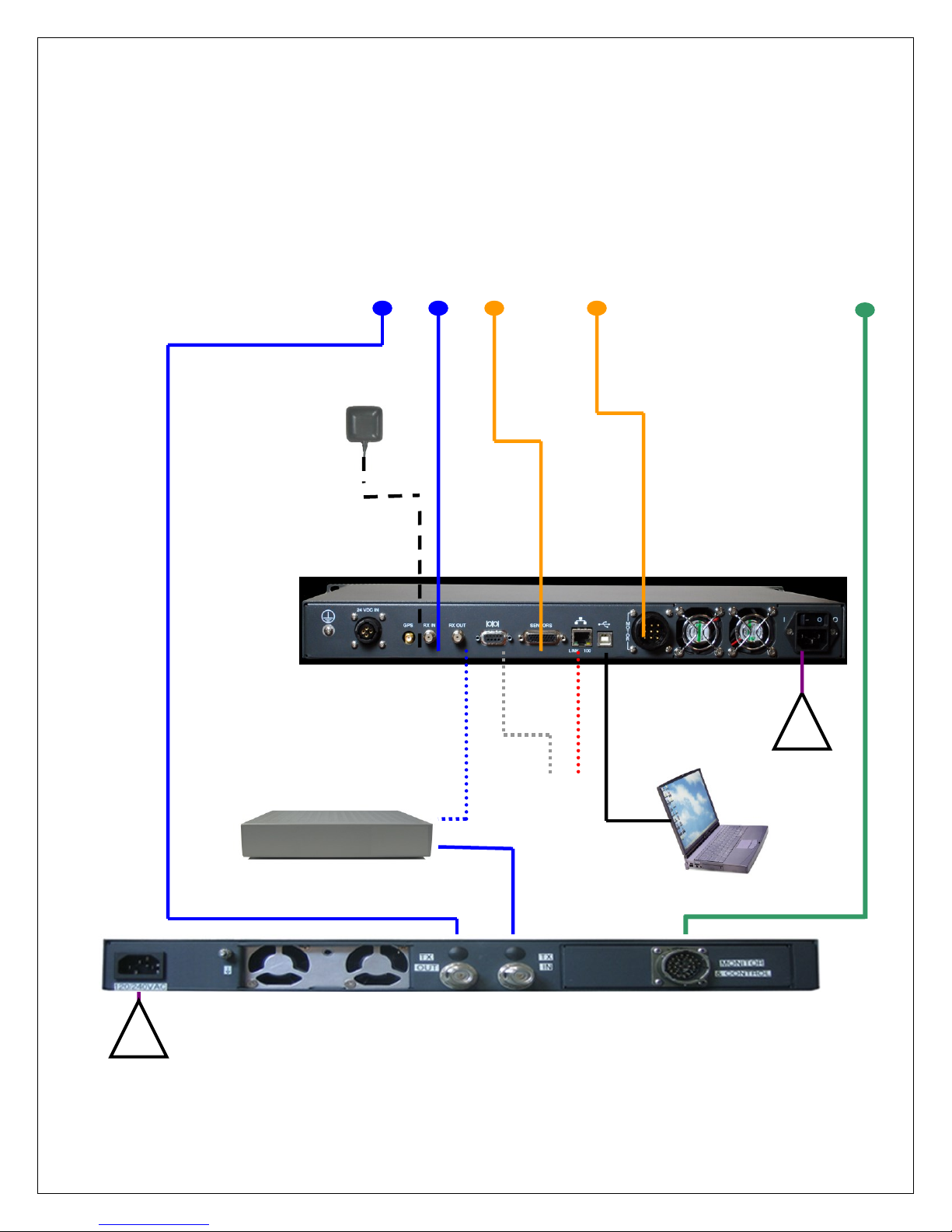
Note *: Network Port and Serial Port of Controller could be used to communicate with
integrated modems/beacon receiver and/or viewing controller interface via web browser or
software application. See corresponding VSAT based configuration manual for details on
network connectivity
Optional PC
Software Front
Panel DB9 Interface
Connection – See
Appendix for details
depending on
Integrated BUC
USB Cable
(Optional for
Controller M&C)
BUC M&C Cable
NO DC POWER
PASS IN TX
COAX – DC
BLOCKED
GPS/GLONASS
ANTENNA
DC
BLOCK*
!
BUC AC/DC Power Cable
MOTOR
AND
SENSOR
CABLES
Disclaimer: The front panel LED’s may
not work for some BUC’s.
100 - 260VAC
Option 7: PowerSmart 2480 with Integrated BUC Connectivity (Separate AC/DC
Power and M&C cables)

18
5. Installation
5.1. Rack Installation
If you are installing the iNetVu® PowerSmart 2480 onto a rack, ensure that you use supporting rails or a
shelf to support the weight of the iNetVu® PowerSmart 2480, and use the appropriate machine screws to
fasten the unit to the rack face.
5.2. Setup and Operation
1. Connect all of the cables and components as depicted in section 4 of this manual. The network or
console connection from the controller is dependent on the service used. Refer to the corresponding
configuration manual to determine the type of cabling to your modem or beacon receiver if applicable.
2. Power ON the Powersmart 2480, Controller, PC and Modem/beacon receiver (if applicable)
3. Configure the 7000 Controller as explained in the iNetVu Configuration Manual – Service Edition),
where “Service” represents the VSAT vendor (iDirect, HNS, etc), Beacon Receiver, or Stand Alone
(DVB).
4. Click on the “Find Satellite” button once configuration is complete. This can be done via the front panel
or software.
5. For integrated BUC’s with M&C Capability, once the system has finished peaking on signal, you may
enable the transmitter switch from the front panel.
6. Congratulations! Your system should be online within seconds. If the BUC alarm goes off, shut down
the BUC power and troubleshoot before proceeding.
7. Switch the Transmit and Power OFF from PowerSmart 2480 front panel and stow the platform when
you are done!
CAUTION! Ensure the transmit switch is turned off when using integrated BUC’s prior to powering on
the external power supply

19
APPENDIX A – Powersmart 2480 with MATCHBOX
WAVESTREAM BUC
Powersmart PC Software Interface Device
If the user would like to access the software interface to the BUC via the Power Smart 2480, the following
RS485 adapter along with a DB-9 Straight Male to Male RS-232 serial cable should be used.
Other interface devices may possibly have other pinouts, and therefore require a custom cable. (See page 6
for pinout requirements of the PowerSmart 2480). Users need to make sure the PC Serial Interface or cable
matches the pins/signals on the PowerSmart front panel DB9 Female connector.
Fig. 4: RS-485 Model 485USB9F-4W from B&B Electronics
Fig. 5: Male to Male – DB9 Straight through serial cable
20
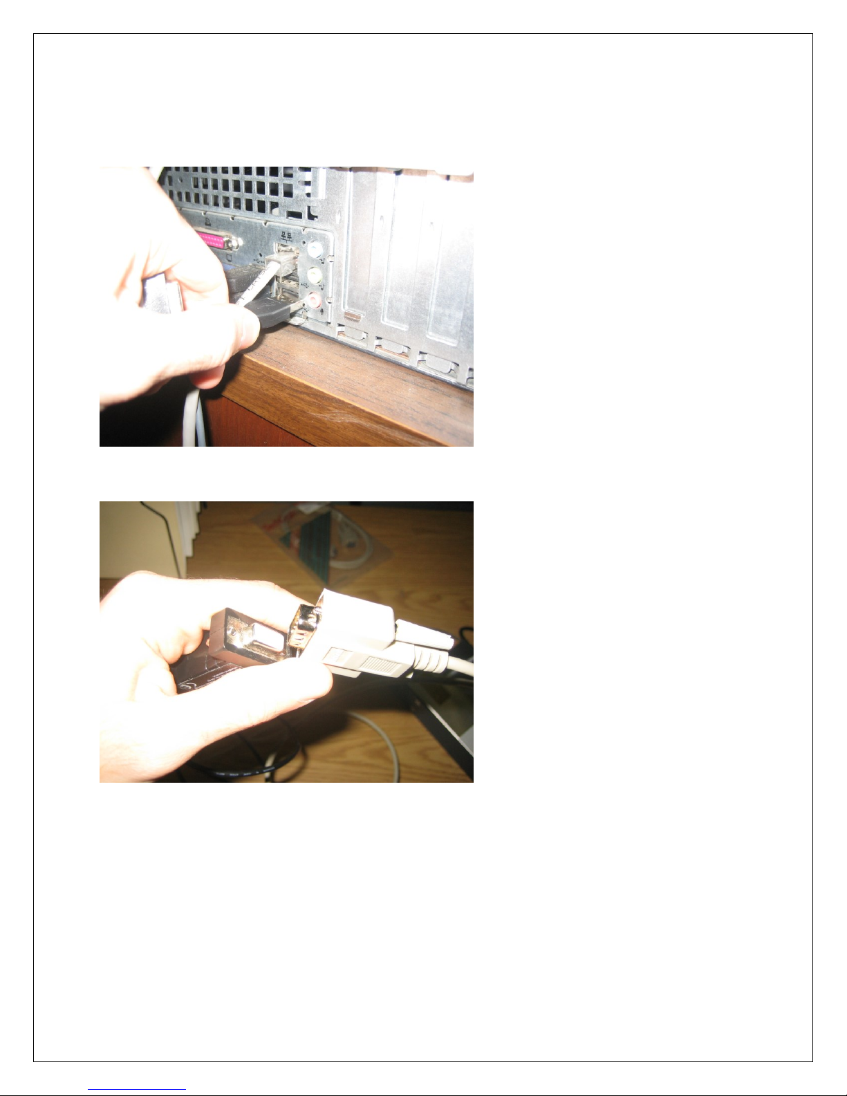
Procedure
1. Ensure power smart is powered OFF
2. Plug the USB end of the RS-485 cable into a USB port of the PC
3. Plug the Female end of the RS-485 device into either end of the male to male DB9 serial cable.
21
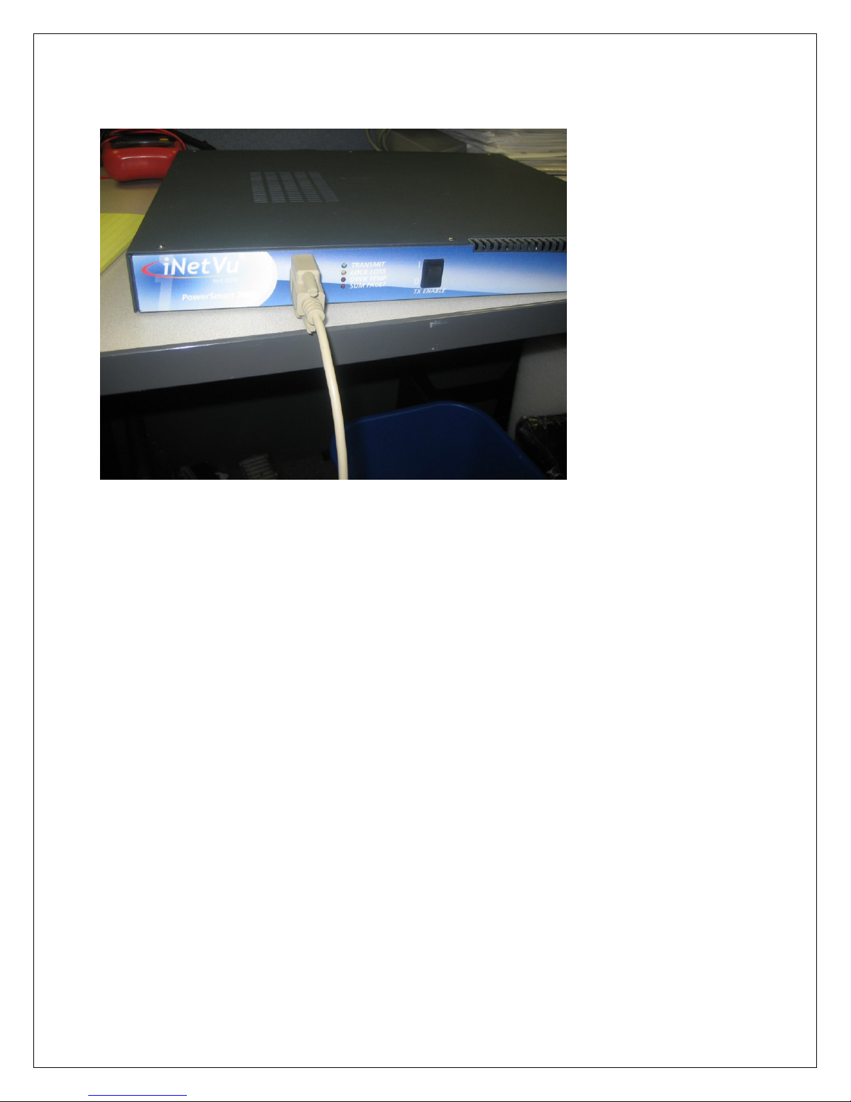
4. Plug the remaining end of the male to male DB9 serial cable into the female 9-pin port of the
powersmart.
5. Power ON the iNetVuTM PowerSmart 2480
6. Refer to Wavestream Manual for software installation and use. Contact the manufacturer for further
information.
 Loading...