

iNetVu STM Satlink 2900, STM Satlink 2000, Nera Satlink 1000 / STM Satlink 1910 User Manual
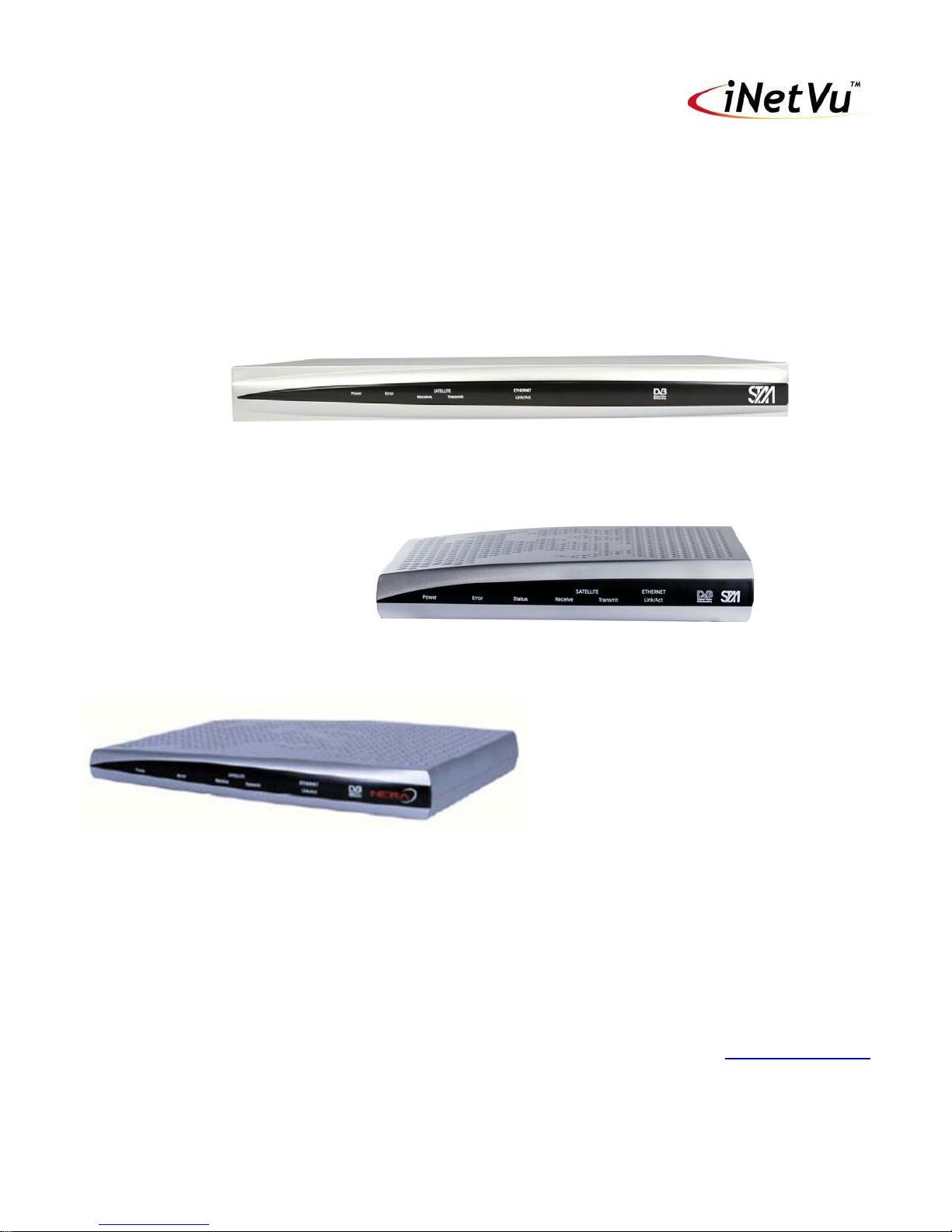
STM Satlink 2900
STM Satlink 2000
Nera/STM and th e iNetVu® 7000 Series Controller
Nera Satlink 1000 / STM Satlink 1910
1-877-iNetVu6
www.c-comsat.com
Revision 3.0
May 25, 2015

INETVU® MOBILE SYSTEM QUICK START – NERA & STM
This page is intentionally left blank.
C-COM Satellite Systems Inc. Page 2
INETVU® MOBILE SYSTEM QUICK START – NERA & STM
1.1 Safety and Warning Infor m ati on
For your safety and protection the following important safety information should be reviewed before
installation, configuration and use of the iNetVu Satellite Platform System and Modem equipment. It is
also recommended to read the manual in its entirety prior to setup and operation.
Warning: The following general safety precautions must be observed during all phases of setup and
operation of this equipment. Failure to comply with these precautions or with specific warnings
elsewhere in this documentation violates safety standards of design, manufacture and intended use of
the equipment. C-COM Satellites Systems Inc. assumes no liability for the customer’s failure to comply
with these requirements.
This situation or practice might result in property or
equipment damage. Ensure Sensor and Motor cables are
connected prior to powering on 7000 Series Controller. Do not
connect or disconnect cables once controller has been
powered on. It is recommended that controller is properly
grounded at all times.
C-COM Satellite Systems Inc. Page 3

INETVU® MOBILE SYSTEM QUICK START – NERA & STM
1.2 System Overview
The iNetVu
system for a foldable two-way satellite antenna. It has been designed to automatically find and acquire
the satellite beam and the position based on both a GPS position reading as well as other positioning
parameters. It is targeted for mobile users that require high speed Internet access in remote locations
where cable and DSL do not exist. It provides two-way, high-speed data communications over satellite.
iNetVu™ empowers mobile users with the ability to stop anywhere there is Satellite coverage and
access Internet at broadband speeds. The iNetVu™ Mobile application consists of the iNetVu™ Mobile
software 7000 software (for the 7000 Series Controller)
iNetVu™ Mobile Application
Key Features:
• Automatic re-peak on satellite upon signal loss.
• Automatic dish stow if Mobile Platform moves
• If the vehicle is moved before the dish is stowed, the dish will sense movement and will
• The dish will not transmit unless it is pointed adequately to meet cross-polarization
• The system will automatically find any satellite from any point on the Earth within its coverage
• Displays comprehensive information about the satellite, dish, motors, GPS, compass, control
• Finds the satellite, peaks the signal strength and selects the optimal path to perform the selected
• Simple to install, configure and operate.
™
Mobile Satellite Internet system is an automatic scanner, polarizer and beam positioning
automatically begin stowing itself.
specifications.
area.
box, and modem.
satellite, allowing the customer’s computer to be online as soon as possible
C-COM Satellite Systems Inc. Page 4
INETVU® MOBILE SYSTEM QUICK START – NERA & STM
Service Type
Modem Firmware
IMS 7000 S/W
IMS F/ W
Interface
Nera Satlink 1000
STM Satlink 1910
9.0.1.45+
7.2.2+
7.2.2.0+
SNMP and CO M
Interface
STM Satlink 2000
STM Satlink 2900
15.0.0.31+
7.5.6+
7.5.6.1+
SNMP and COM
Interface
1.3 Pre-Configuration Check Li st
Prior to installing IMS and configuring your system, verify that you are using the minimum
requirements listed below.
Note: Please contact C-COM if you require more information about modem compatibility as these
may change without further notice.
Note: Installed Software and Controller Firmware versions MUST be identical for normal operation
IP Address of Satellite Modem (if using SNMP Interface)
Satellite Name and Coordinate
Transmit and Receive Polarization (Horizontal/Vertical)
COM port users must use a standard male to female DB9 cable with the NULL Modem Adapter
attached to the controller end of the cable.
SNMP Interface Users
The SNMP community must be configured to “rw” via CLI by using the device snmp community
command
There are 2 methods to communicate with modem and perform the steps listed. One is HyperTerminal
and the other is via Telnet. We will illustrate the telnet method. Type the following command to make the
change.
Note: commands are to be typed without quotations.
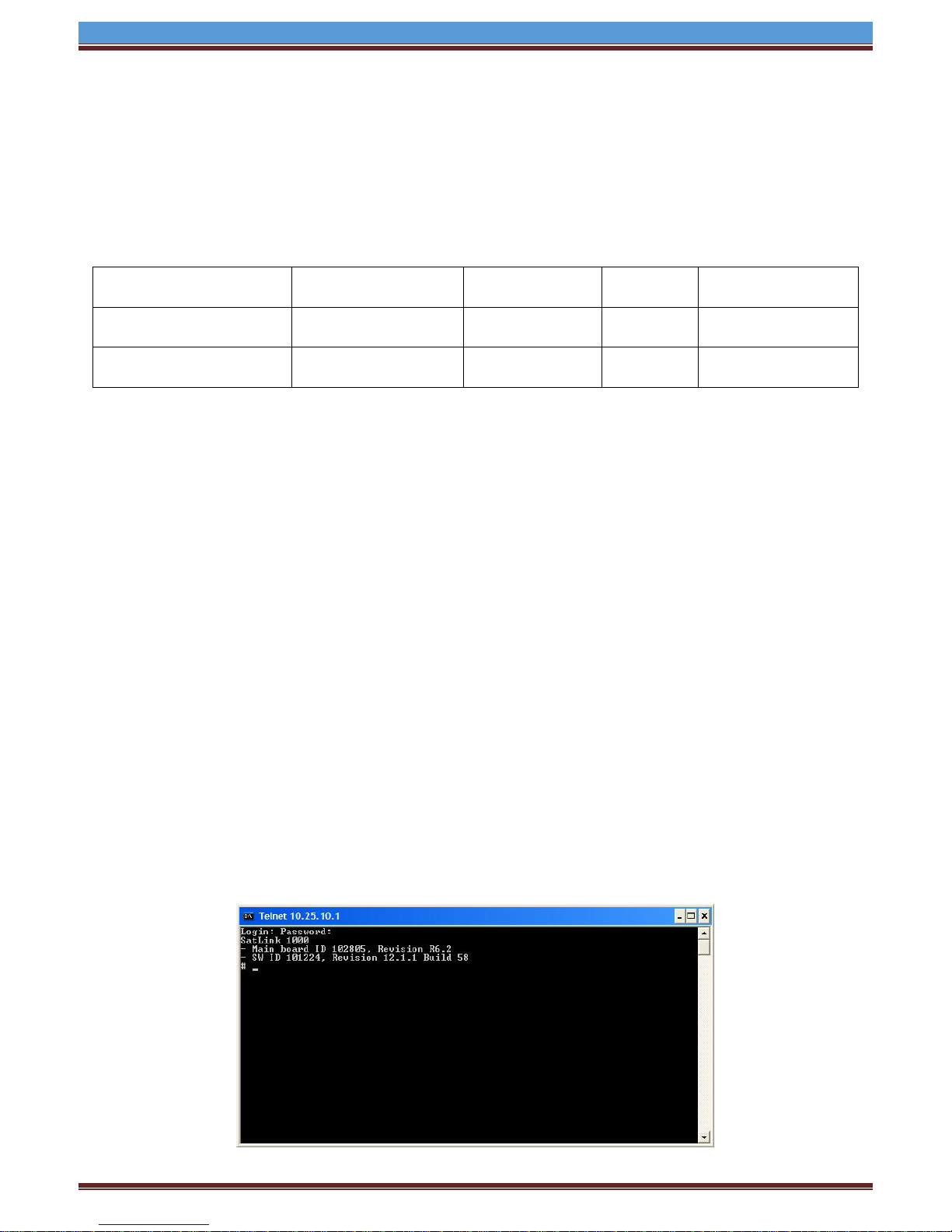
1. Open Command Prompt after establishing a network between the PC and the Modem. Ensure
2. Type “telnet ‘modem ip’” and press Enter
3. Enter user name: “root”
4. Enter Password “nera” for Satlink 1000 and “balder1” for STM Satlink 1910/2000/2900 (default).
5. The following screen will appear
and the device manager add snmp command. This change is only required to be done once.
you can ping the modem from your PC
Check with service provider otherwise
C-COM Satellite Systems Inc. Page 5

INETVU® MOBILE SYSTEM QUICK START – NERA & STM
Define an access type with the name ―PUBLIC, with read-write maximum access rights and on the
SNMP request‘s modem IP address and net mask.
6. Type the following into the command line “device snmp community PUBLIC rw “modem IP”
“modem net mask”. Press Enter.
7. Type “save config” and Press Enter.
8. To confirm the access setting type “device snmp show”
SNMP management access:
----------------------Community String Access IpAddress Subnet
prtg Read only 213.52.18.32 255.255.255.240
public Read/Write 0.0.0.0 0.0.0.0
PUBLIC Read/Write 10.110.2.233 255.255.255.248
To allow SNMP access from subnet modem IP and 255.255.255.255 via local LAN Interface.
9. Type “device manager add snmp 1.0.0.0.0.0.0.0” Press Enter.
10. Type “save config” and Press Enter.
11. To confirm the access setting type “device manager show”
Management access:
-----------------Access Interface IpAddress Subnet
SNMP 3 0.0.0.0 0.0.0.0
SNMP 1 0.0.0.0 0.0.0.0
12. Contact NOC for more information on changing the setting.
C-COM Satellite Systems Inc. Page 6
INETVU® MOBILE SYSTEM QUICK START – NERA & STM
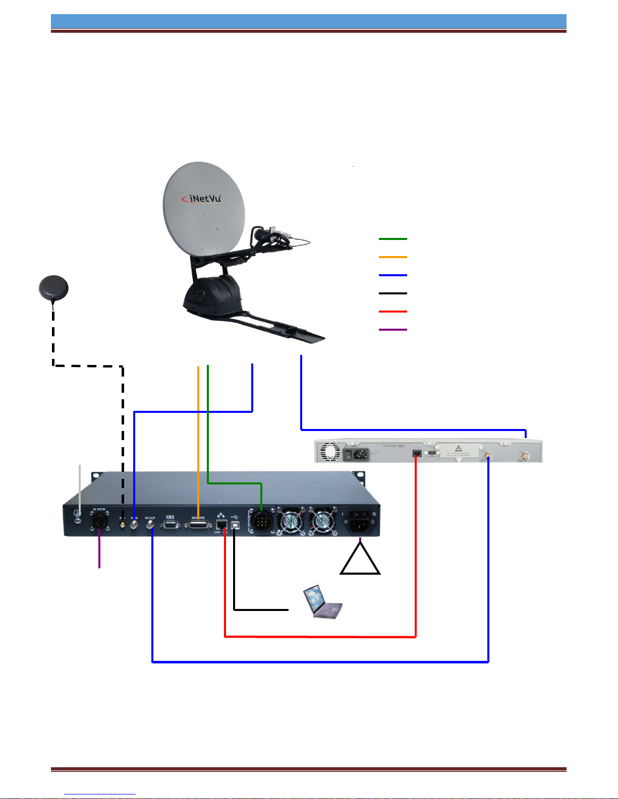
90 - 264 VAC
RX
TX
Motor
Sensor
USB Cable
SAT OUT
RX IN
SAT IN
IP: A.B.C.D+1
IP: A.B.C.D
X-OVER
RX
Motor Control Cable
Sensor Cable
RG6 Coaxial Cable
USB Cable
Network Cable
Power Cable
STM Satlink 1910
GPS
*Ground
24 VDC
1.4 System Wiring with STM Servi c e
1.5 USB Interface Connection – Satlink 1910 System Wiring
Antenna
protection
OUT
Input
(option)
Cable
SUB: 255.X.Y.Z
GW: A.B.C.D
USB Interface System Wiring Diagram for STM Series
1.
Cable
SUB: 255.X.Y.Z
Network Cable
C-COM Satellite Systems Inc. Page 7
 Loading...