

iNetVu Fly-1801 User Manual
C-COM Satellite Systems Inc. Page 1 of 39
iNetVu
®
Fly-1801 User Manual
iNetVu® Fly-1801 User Manual
The iNetVu® brand and logo are registered trademarks of C-COM Satellite Systems, Inc.
© Copyright 2018 C-COM Satellite Systems, Inc.
1-877-iNetVu6
www.c-comsat.com
Revision 1.0
October 25, 2018

C-COM Satellite Systems Inc. Page 2 of 39
iNetVu
®
Fly-1801 User Manual
This page is intentionally left blank.
C-COM Satellite Systems Inc. Page 3 of 39
iNetVu
®
Fly-1801 User Manual
Copyright © 2018. All rights reserved. C-COM Satellite Systems Inc.
This document contains information, which is protected by copyright. All rights reserved. Reproduction,
adaptation, or translation without prior written permission is prohibited, except as followed under the
copyright laws.
Both the iNetVu® and C-COM names and logos are registered trademarks of C-COM Satellite Systems Inc.
Intel® Pentium is a registered trademark of Intel Corporation. Microsoft, Windows, Windows NT and
MapPoint are registered trademarks of Microsoft Corporation.
All other product names mentioned in this manual may be trademarks or registered trademarks of their
respective companies and are the sole property of their respective manufacturers.
Proprietary Notice: This document contains information that is proprietary and confidential to CCOM Satellite Systems, Inc., and is intended for internal and or C-COM Satellite Systems Inc.
authorized partners use only. No part of this document may be copied or reproduced in any way,
without prior written permission of C-COM Satellite Systems, Inc.

C-COM Satellite Systems Inc. Page 4 of 39
iNetVu
®
Fly-1801 User Manual
Table of Contents
1. Introduction .............................................................................................................................5
1.1 About This Manual ................................................................................................................... 5
1.2 Power Consumption ................................................................................................................ 6
2. System Connections ..............................................................................................................7
2.1 Typical Connection with Ku Service – PC Free ............................................................... 7
2.2 Typical Network Interface Connection - Ku ...................................................................... 8
2.3 Typical USB Communication Interface - Ku ..................................................................... 9
3. Assembly and Disassembly ................................................................................................ 10
3.1 Assembly Procedure ............................................................................................................. 10
3.2 Disassembly Procedure ....................................................................................................... 26
Appendix 1: Default Limits and Configuration Data Tables ................................................... 39
C-COM Satellite Systems Inc. Page 5 of 39
iNetVu
®
Fly-1801 User Manual
1. Introduction
1.1 About This Manual
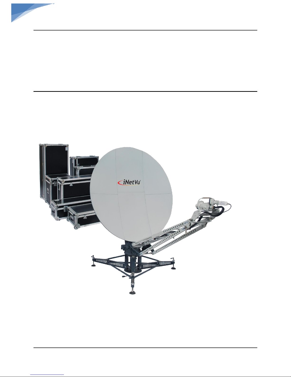
The iNetVu® Fly-1801 Flyaway System Installation and Operation are described in this manual.
An electronic version of this manual is included on the iNetVu® flash drive that came with your
system.
Fig. 1: iNetVu
®
Fly-1801 Flyaway Antenna
C-COM Satellite Systems Inc. Page 6 of 39
iNetVu
®
Fly-1801 User Manual
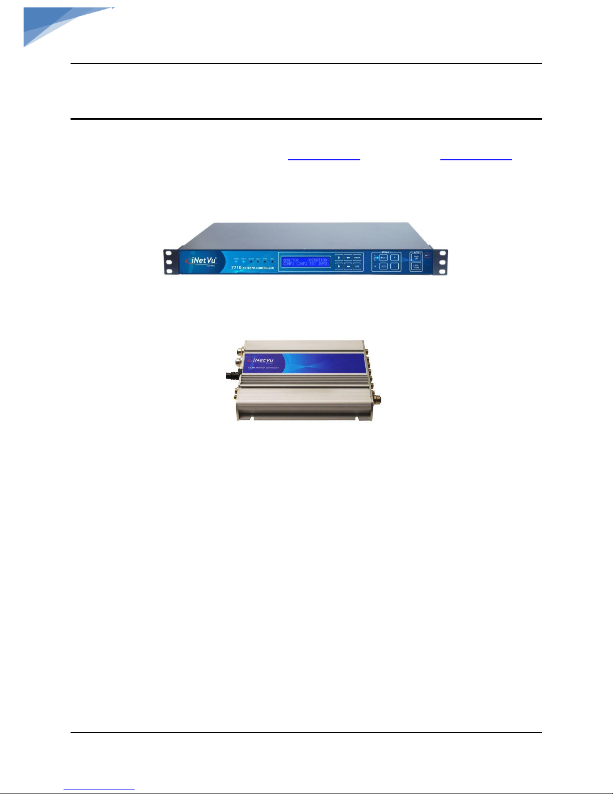
1.2 Power Consumption
Minimum Power Consumption: 24VDC@0.19A for 7710 alone (24VDC@0.13A for
7720).
Maximum Power Consumption: 24 @ 13A
Controller AC Universal Input: 100 ~ 240 VAC, 50/60 Hz
Fig. 2: iNetVu
®
7710 Controller
Fig. 3: iNetVu
®
7720 Remote Drive Module
The iNetVu® Fly-1801 systems offer the following capabilities and features:
• 2-Axis DC motor drive system on AZ & EL.
• Motorized 3
rd
axis (POL).
• Satellite acquisition within 5 minutes (under normal operating conditions)
• Compatible with configured satellite over the Ka or Ku Band.
• Fully automatic, software controlled satellite acquisition
• Optimized signal reception and transmission
• Self-calibrating and tuning after satellite acquisition
• Integrated with some of the world`s leading satellite service providers.
• Easily assembled, ruggedized carry cases.
C-COM Satellite Systems Inc. Page 7 of 39
iNetVu
®
Fly-1801 User Manual
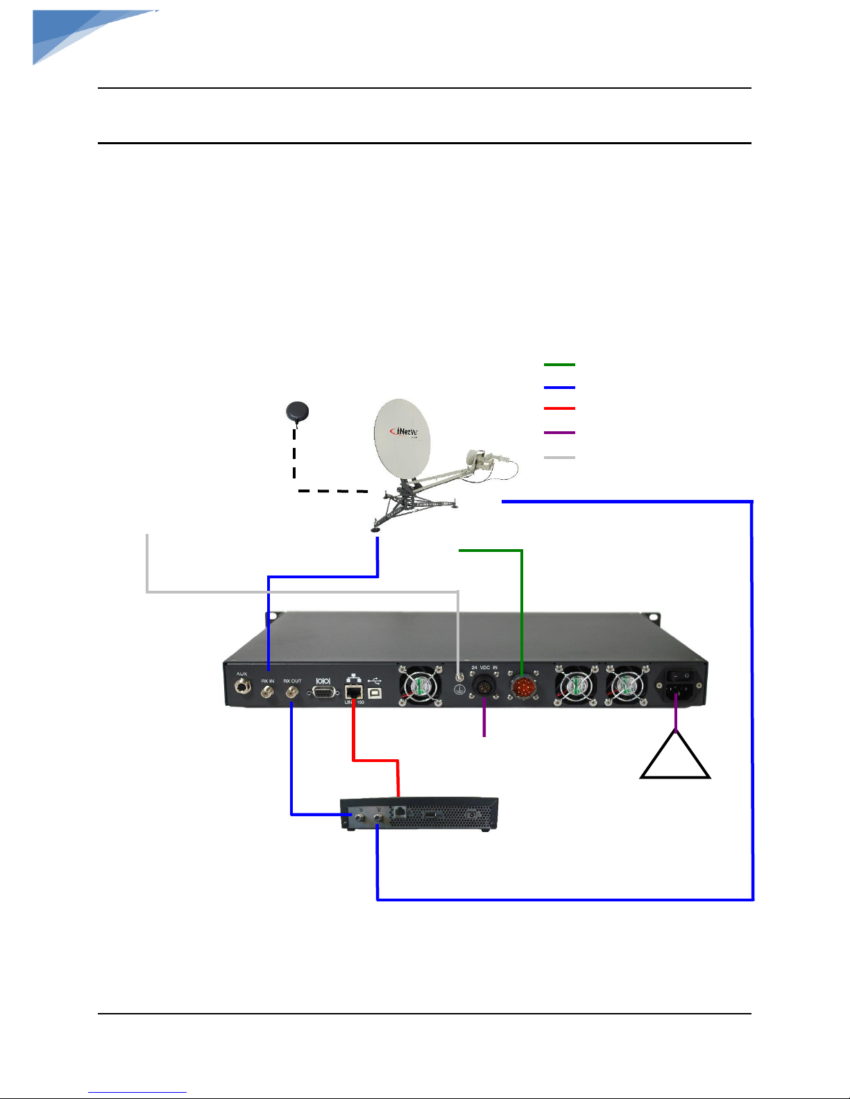
2. System Connections
The iNetVu
®
New Generation Fly-1801 Antenna have been designed to operate with
the iNetVu® 7710 Controller and a 7720 Remote Drive Module (Onboard). The typical
connection configuration for each service will be the same regardless of the Satellite Modem /
VSAT. However, the configuration parameters for Satellite Modem / VSAT Communication will
differ depending on service. The user may select the connection that corresponds to his/her
preferred system setup prior to configuration. The system connections shown in this section are
for Ku systems.
2.1 Typical Connection with Ku Service – PC Free
Fig. 4: iNetVu
®
7710 Controller & Ku Antenna Connection with PC Free Configuration
TX
RX
RX IN
iNetVu™ Flyaway
Platform
24 VDC Power input
(If VAC not available)
*Ground
protection
External
grounding
connection
RG6 Coaxial Cable
Combined Motor & Data
Network Cable
Power Cable
* Ground Connection
GPS/Glonass
Antenna
100 - 240VAC
RX OUT
Network
Cable
RX IN
Satellite Modem / VSAT
TX OUT
COMBINED MOTOR &
DATA CONTROL CABLE
*Recommended for proper
grounding of iNetVu® systems.
C-COM Satellite Systems Inc. Page 8 of 39
iNetVu
®
Fly-1801 User Manual
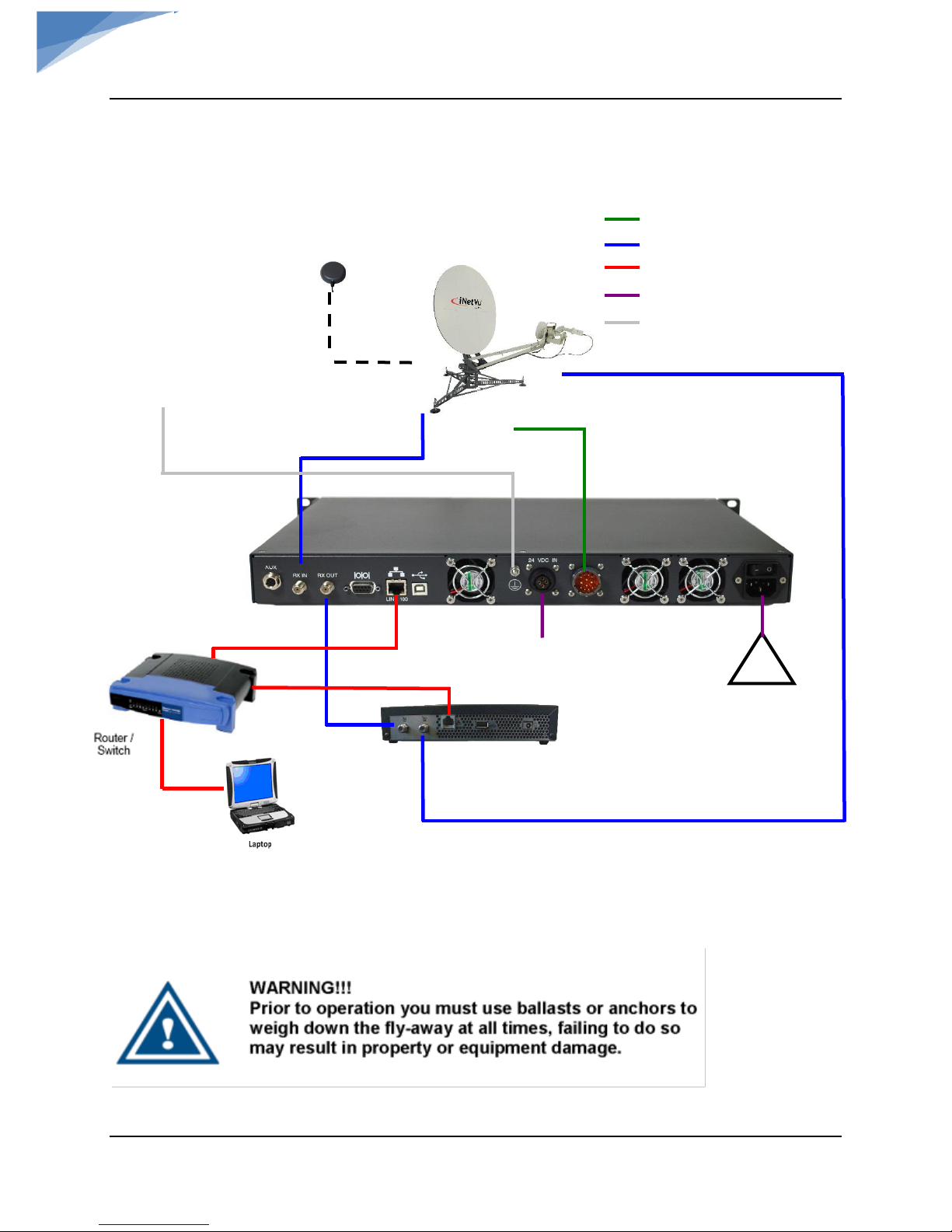
2.2 Typical Network Interface Connection - Ku
Fig. 5: iNetVu
®
LAN interface Connection Configuration with Ku Antenna
*Recommended for proper grounding of iNetVu® systems.
TX
RX
RX IN
iNetVu™ Flyaway
Platform
24 VDC Power input
(If VAC not available)
*Ground
protection
External
grounding
connection
GPS/Glonass
Antenna
100 - 240VAC
RX OUT
Network
Cable
RX IN
Satellite Modem / VSAT
TX OUT
COMBINED MOTOR &
DATA CONTROL CABLE
RG6 Coaxial Cable
Combined Motor & Data
Network Cable
Power Cable
* Ground Connection
C-COM Satellite Systems Inc. Page 9 of 39
iNetVu
®
Fly-1801 User Manual
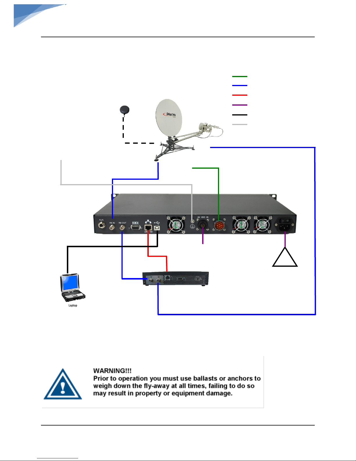
2.3 Typical USB Communication Interface - Ku
Fig. 6: USB Interface Connection with Ku Antenna
*Recommended for proper grounding of iNetVu® systems.
TX
RX
RX IN
iNetVu™ Flyaway
Platform
24 VDC Power input
(If VAC not available)
*Ground
protection
External
grounding
connection
GPS/Glonass
Antenna
100 - 240VAC
RX OUT
Network
Cable
RX IN
Satellite Modem / VSAT
TX OUT
COMBINED MOTOR &
DATA CONTROL CABLE
RG6 Coaxial Cable
Network Cable
Power Cable
Combined Motor & Data Control Cable
USB Cable
* Ground Connection
C-COM Satellite Systems Inc. Page 10 of 39
iNetVu
®
Fly-1801 User Manual
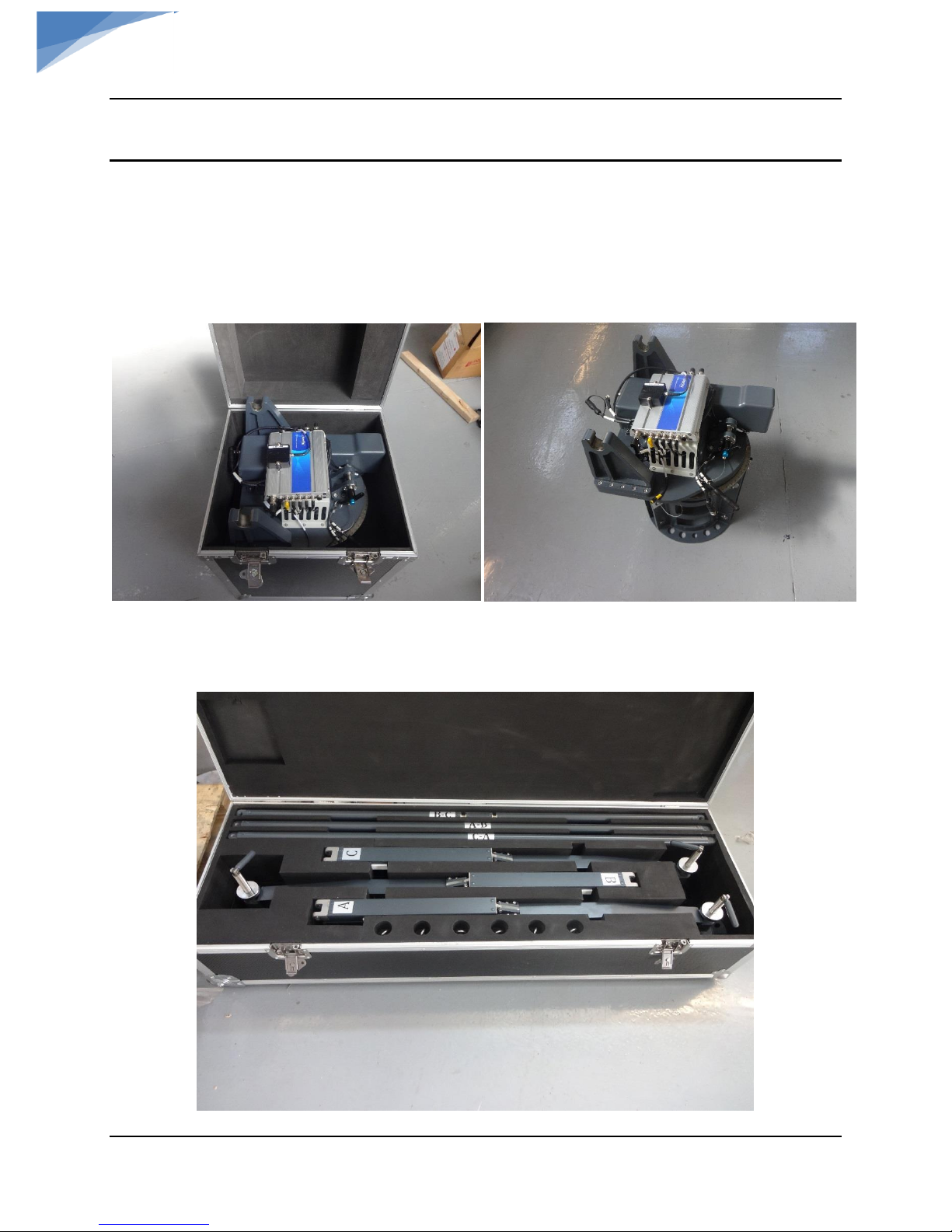
3. Assembly and Disassembly
3.1 Assembly Procedure
Note: a Minimum of two or more people is required for assembly/disassembly.
1) Remove AZ assembly (Rotary Platform) from case.
2) Remove tripod support legs from the case and install on the AZ assembly. Each support leg
is labelled so install in the corresponding position on the AZ assembly.
C-COM Satellite Systems Inc. Page 11 of 39
iNetVu
®
Fly-1801 User Manual
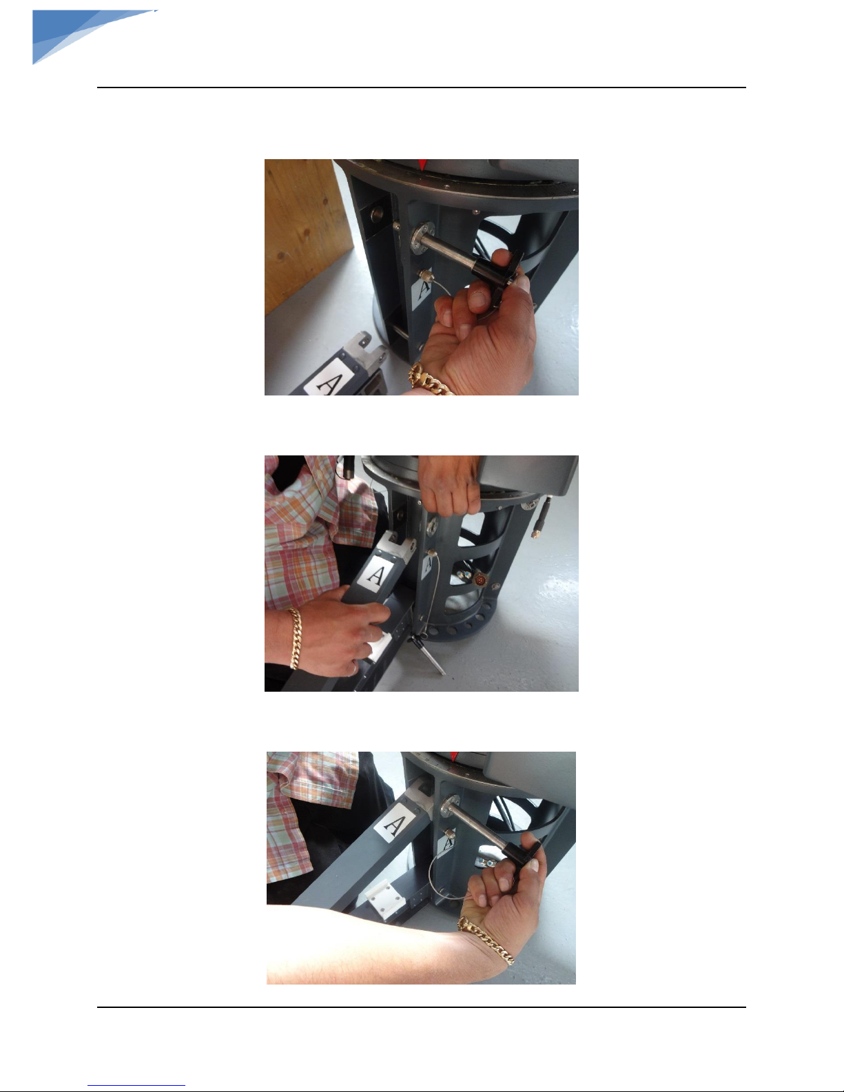
a. Remove pin on AZ assembly to install leg(s)
b. Lift the AZ assembly and engage the support leg & support arm.
c. Insert the pin to lock the support leg in place.

C-COM Satellite Systems Inc. Page 12 of 39
iNetVu
®
Fly-1801 User Manual
d. Turn the foot handle (CCW) to lower the antenna foot all the way for better stability,
turn the upper locking wheel on the foot to lock adjusted foot height. Foot should be
adjusted to level the antenna if assembled on unlevelled ground.
3) Continue with the same process as above for the remaining 2 support legs.
4) Install support rods between the corresponding support legs. Follow identification letters
on Rods and Legs.
Locking Hand
Wheel
Foot Handle
Foot lowered
all the way
 Loading...