

iNetVu 1500, 1800, 985, 980, 1200 Installation Manual
...
iNetVu® Mobile Installation Manual Page 1 of 93
iNetVu® Mobile Platform Installation Manual
The iNetVu® brand and logo are registered trademarks of C-COM Satellite Systems, Inc.
© Copyright 2017 C-COM Satellite Systems, Inc.
1-877-iNetVu6
www.c-comsat.com
Revision 030
December 8, 2017

iNetVu® Mobile Installation Manual Page 2 of 93
This page is intentionally left blank.

iNetVu® Mobile Installation Manual Page 3 of 93
Table of Contents
Chapter 1: Introduction ............................................................................................................... 7
1.1 About This Manual ...................................................................................................... 7
1.2 Important Safety Information ....................................................................................... 7
1.3 System Overview ........................................................................................................ 8
1.4 iNetVu® Antenna ......................................................................................................... 9
1.5 iNetVu® Controllers ....................................................................................................10
Chapter 2: General Mobile Platform Specifications ...................................................................11
2.1 Mounting Surface ......................................................................................................11
2.2 Cable Lengths ...........................................................................................................11
2.3 Roof Clearance ..........................................................................................................12
2.4 Weight Support ..........................................................................................................13
2.5 Additional Considerations ..........................................................................................13
Chapter 3: iNetVu® Mobile System Installation ..........................................................................14
3.1 General......................................................................................................................14
3.2 Recommended Tools .................................................................................................15
3.3 Installation Overview..................................................................................................16
3.4 Mobile Platform Front / Back Orientation ...................................................................17
3.5 Direct Installation to Vehicle .......................................................................................18
3.5.1 Clearance requirements for the iNetVu® 1800 Mobile Platforms ............................ 19
3.5.2 Clearance requirements for the iNetVu® 1800 C-Circular Band Platform ............... 20
3.5.3 Clearance requirements for the iNetVu 1500 KU-Band Platform ............................ 21
3.5.4 Clearance requirements for the iNetVu 1500 INSAT C-Band Platform ................... 23
3.5.5 Clearance Requirements for 1500 Standard C-Band Standard Linear Platform ..... 25
3.5.6 Clearance Requirements for the iNetVu 1200 Mobile Platform .............................. 27
3.5.7 Clearance Requirements for the iNetVu 980 Mobile Platform ................................ 29
3.5.8 iNetVuTM 1800 Mobile Platform Base Dimensions .................................................. 32
3.5.9 iNetVuTM 1200/1500 Mobile Platform Base Dimensions ......................................... 33
3.5.10 iNetVuTM 980 Mobile Platform Base Dimensions .................................................... 34
3.6 Alternative Installation to Vehicle Using Thule® Racking System ..............................39
3.7 iNetVu® Mobile System Wiring ...................................................................................40
Chapter 4: Additional Assemblies and Modifications .................................................................41
4.1 Installing Reflector to iNetVu® 1200 Mobile Platform .................................................41
4.2 Installing Reflector to iNetVu® 1500 Mobile Platform ..................................................47
4.3 Installing Reflector to iNetVu® 1800 Mobile Platform ..................................................51
4.4 Installing POL Feed Horn Assemblies to iNetVu® 1800 Mobile Platform ...................54
4.4.1 Ku POL Feed Polarization ..................................................................................... 54
4.4.2 C-Circular POL Feed Horn ..................................................................................... 58
4.5 Installing BUC to iNetVu® 980 Mobile Platform using Universal Bracket Kit ..............60
4.6 Installing BUC to iNetVu® 1200/1500/1800 Mobile Platform using Universal Bracket Kit ............62
4.7 Installing BUC Using Universal Mounting Clamp Kit ..................................................65
4.8 Adjusting Polarization for iNetVu® 980 Mobile Platform..............................................71
4.9 Removing the 90 Degree OMT Elbow on iNetVu® 750 Mobile Platform ..................... 73
4.10 Attaching Feed Arm to iNetVu® 950 / 980 Reflector ..................................................76
4.11 Installing Flexible Waveguide onto A980 Mobile Platform ..........................................77
4.12 Installing Flexible Waveguide onto 1800 Mobile Platform ..........................................79
4.13 A1200 B/C Co-Pol Installation Assembly ...................................................................80
4.14 Recognizing and Switching Left-Hand and Right-Hand Polarity on Circular C-Band ..85
4.15 C-BAND WR137 to N type Adapter Installation ..........................................................87
Appendix A: Replacing Gas Spring Mounting Brackets .............................................................89
Appendix B: Declaration of Conformity ......................................................................................93
iNetVu® Mobile Installation Manual Page 4 of 93
Copyright © 2017. All rights reserved. C-COM Satellite Systems Inc.
This document contains information, which is protected by copyright. All rights reserved. Reproduction,
adaptation, or translation without prior written permission is prohibited, except as followed under the
copyright laws.
Both the iNetVu® and C-COM names and logos are registered trademarks of C-COM Satellite Systems
Inc.
Intel® Pentium is a registered trademark of Intel Corporation. All Microsoft products are registered
trademarks of Microsoft Corporation.
All other product names mentioned in this manual may be trademarks or registered trademarks of their
respective companies and are the sole property of their respective manufacturers.

iNetVu® Mobile Installation Manual Page 5 of 93
FCC and INDUSTRY CANADA INFORMATION TO THE USER:
The FCC and Industry Canada have imposed the following conditions when operating, installing
and deploying iNetVu® Mobile Earth Stations and is mandatory for all installations made within
the Continental United States and Canada as well as Hawaii, Alaska, Puerto Rico, the U.S.
Virgin Islands and other U.S. Territories. The FCC requires that a certified installer perform the
installation. It is also strongly recommended that a qualified professional RV dealer/installer
mount the system on your vehicle. These conditions are also required by C-COM for all other
installed locations.
All iNetVu® Mobile earth station installers must be C-COM Certified, and must have specifically
acknowledged the requirements for iNetVu® Mobile installations, which are as follows:
1. “Installation” is the physical mounting and wiring of the Satellite provider’s earth station
on a vehicle or other stationary site in order to prepare for correct operation. Only
Certified C-COM iNetVu installers may perform the installation and removal of an
iNetVu® Mobile system.
2. “Deployment” means the raising, pointing and orienting of the earth station to the
communicating satellite, every time it is raised from a stowed position for use. The
deployment of an iNetVu® Mobile system must only be done by a trained installer or by a
consumer using the deployment software.
3. Installers shall install the iNetVu® systems only in locations that are not readily
accessible to children and in a manner that prevents human exposure to potential
radiation hazards.
4. For large vehicles with roof mounts, the height of the bottom lip of the earth station when
fully deployed must be at least six feet above the ground at all times, or six feet above a
surrounding surface which a person may easily access.
5. If a roof access ladder or any other means of access to the roof is installed on the
vehicle, then the ladder or access must be blocked by a suitable rope or other barrier
while the earth station is deployed or in operation. The installer must provide this rope
or barrier directly to the end user at the time of installation and advise the user to use it
at all times when the earth station is deployed or in operation. Warning signs shall also
be provided by the installer to the end user to be posted on the rope or other barrier
warning all persons not to attempt to access the roof of the vehicle while the earth
station is deployed or in operation.
6. Warning signs shall be posted at prominent locations on the earth station informing all
persons of the danger of harmful radiation from the earth station while it is deployed or
while in operation.
7. The iNetVu® Mobile system may only be operated when the vehicle is stationary.
8. The installer must inform the end user that the vehicle must be stabilized during the
transmission, to prevent movement of the vehicle for any reason, including movement of
persons on or off the vehicle, or high winds. The installer shall advise the end user how
to appropriately stabilize their vehicle.
9. Installers shall be liable for all damages if they fail to comply with the above mandatory
conditions. This includes, but is not limited to damages caused by improper installation
or due to the failure to provide required information to the end user.
10. Installers and end users will be deemed directly liable for any damages resulting from
either of their failure to comply with the above rules. These rules are meant to ensure
that extraordinary precautions and measures are used to prevent satellite interference or
exposure to harmful radiation. C-COM reserves the rights to immediately suspend
without liability or previous notice the operation of the earth station upon detection of
a deviation from its installation or operational requirements until the deviation is

iNetVu® Mobile Installation Manual Page 6 of 93
corrected. In addition, C-COM reserves the right to suspend or cancel the Installer
Certificate of any installer that has not fully complied with these installation requirements.
11. Further, the installer and end user may be directly liable for any damages resulting from
any change undertaken by either of them. Including but not limited to, any modification of
any part of the hardware, software, specific operational frequencies, the authorized
satellite, or the size or other characteristics of the earth station supplied to them by CCOM or C-COM’s authorized representatives.
Note 1:
This equipment has been tested and found to comply with the limits for a Class B digital device,
pursuant to Part 15 of FCC rules. These limits are designed to provide reasonable protection
against harmful interference when the equipment is operated in a residential installation. This
equipment generates, uses, and can radiate radio frequency energy and, if not installed and used
in accordance with this instruction manual, may cause harmful interference with radio
communications. However, there is no guarantee that interference will not occur in a particular
installation. If this equipment does cause harmful interference to radio or television reception,
which can be determined by turning the equipment off and on, the user is encouraged to try to
correct the interference by one or more of the following measures:
• Reorient or relocate the receiving antenna.
• Increase the separation between the equipment and receiver.
• Connect the equipment into an outlet on a circuit different from that to which the receiver
is connected.
• Consult the dealer or an experienced radio / TV technician for help.
Note 2:
This Class B digital apparatus complies with Canadian ICES-003.
iNetVu® Mobile Platform Installation Manual Page 7 of 93
Chapter 1: Introduction
1.1 About This Manual
This manual explains the iNetVu® Mobile System Installation and General Assembly. An
electronic version of this manual is included on the iNetVu® USB Flash Drive that came
with your system.
1.2 Important Safety Information
For your safety and protection, read this entire manual before attempting to install or use
the iNetVu® Mobile System. Keep this manual where you can refer to it if necessary.
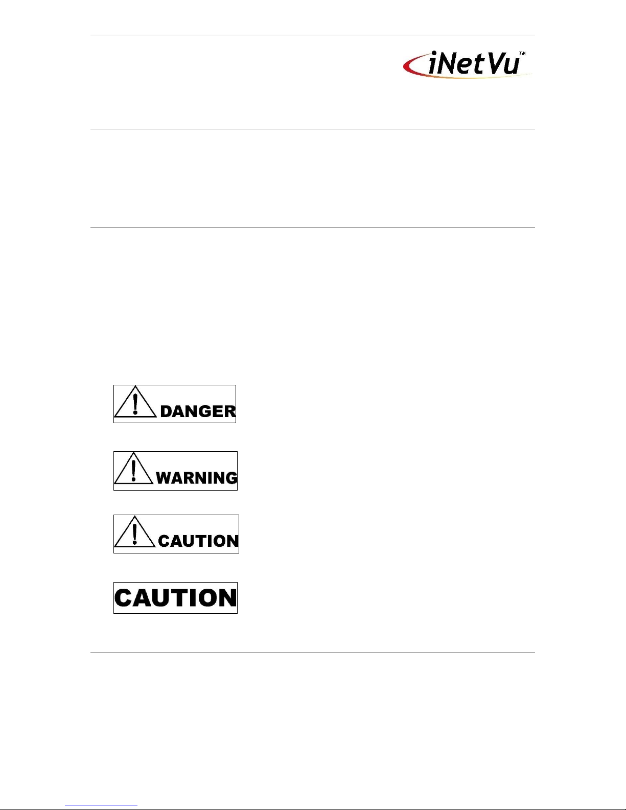
Types of Warnings Used in This Manual
This section introduces the various types of warnings used in this manual to alert you
to possible safety hazards.
Indicates an imminently hazardous situation, which, if
not avoided, will result in death or serious injury.
Indicates a potentially hazardous situation, which, if not
avoided, could result in death or serious injury.
Indicates a potentially hazardous situation, which, if not
avoided, may result in minor or moderate injury.
Indicates a situation or practice that might result in
property or equipment damage.

iNetVu® Mobile Platform Installation Manual Page 8 of 93
1.3 System Overview
The iNetVu® Mobile Satellite Internet system is an automatic scanner, polarizer and
beam positioning system for a foldable two-way satellite antenna. It has been designed
to automatically find and acquire the satellite beam and the position based on both a
GPS position reading as well as other positioning parameters. It is targeted for mobile
users worldwide who require broadband Internet access in large continuous coverage
areas, including remote locations where DSL and Cable and other Internet services do
not exist. It provides two-way, high-speed data communications over satellite. iNetVu®
empowers mobile users with the ability to stop anywhere there is Satellite coverage and
access Internet at broadband speeds.
The mobile system offers the following additional capabilities and features:
• Mobile Platform features a 3-axis DC motor drive system
• Elevation system features a highly reliable linear actuator to control elevation
• All drive components are high strength steel, housed in lubricated housings,
which results in a rigid, highly reliable, system with the minimum of weight
• Reflector is an offset, prime focus, SMC high strength plastic illuminated by a
corrugated horn
• Satellite acquisition and lock in less than 5 minutes (under normal
circumstances)
• Satellite independent – compatible with any configured satellite
• Dish pointing is automatic and fully software controlled
• Optimized signal reception and transmission
• Fast re-acquisition based on last good position
• Interfaces with a full-function controller with features such as automatic stowing,
GPS and flux-gate compass and automatic satellite pointing
• Reliable acquiring, minimal maintenance
• Self-calibrating and tuning after satellite acquisition

iNetVu® Mobile Platform Installation Manual Page 9 of 93
1.4 iNetVu® Antenna
The iNetVu® 1800, 1500, 1200, 985, 980, 755 and 660 Antenna are circular 1.8m, 1.2m,
0.98m, .75m and 0.66m (respectively) two-way Ku-Band satellite dish mounted over an
arm that supports the antenna, Radio Transmitter and Low Noise Block (LNB).
Additionally, the iNetVu® 1500, 1800 Mobile Platforms can be configured for C Band,
and the 1800 for C Circular/ C Linear.
The iNetVu® 950, 750, 740 Antennae are elliptical 0.95m, 0.75m, 0.74m (respectively)
two-way Ku-Band satellite dishes mounted over an arm that supports the antenna plus
the Radio Transmitter and the Low Noise Block (LNB).

iNetVu® Mobile Platform Installation Manual Page 10 of 93
1.5 iNetVu® Controllers
The iNetVu® Antenna Controllers have been designed to automate the operation of
Mobile systems.
Key Features:
• Automatic azimuth, polarization, and elevation pointing calculation
• GPS/Glonass receiver for determining antenna latitude and longitude coordinates
• Fluxgate compass for determining orientation/direction of iNetVu® Mobile
Platform
• Non-volatile, flash memory for storing satellite locations and configuration data
• Automatic dish repositioning to previously accessed satellites (if the vehicle or
structures location is unchanged)
• Slim, 1U high rack or desktop mounted unit
• Continuous monitoring of antenna drive status
• RS-232 remote control serial interface.
• USB interface
• L-Band RF detector to support Ku and C band satellite operations
See the Controller Manuals for more details.

iNetVu® Mobile Platform Installation Manual Page 11 of 93
Chapter 2: General Mobile Platform Specifications
2.1 Mounting Surface
• The mounting surface must be flat within 1/16” (1.6mm)
• A 1½” (38.1mm) diameter hole is needed near the mounting surface for routing of
the control and signal cables.
2.2 Cable Lengths
• The 1800 platforms may require the settings to be adjusted on the AZ & EL axis
when cable used is greater than 50ft and the user experiences overcurrent
errors.
• Adjust speed and Low Platform Current values increasing each by one (+1.0)
until system overcurrent errors are eliminated. It is recommended that operator
contacts C-COM Support and Slow Speed settings do not exceed 9 while Low
Platform Current maximum is 10.

iNetVu® Mobile Platform Installation Manual Page 12 of 93
2.3 Roof Clearance
All iNetVu® systems require a specific unobstructed clearance from any other roofmounted equipment such as air conditioners, air vents, etc. See section 3.5 for
geometrical coordinates.

iNetVu® Mobile Platform Installation Manual Page 13 of 93
2.4 Weight Support
All iNetVu® Mobile systems are capable of being mounted to a vehicle that can support
the following constraints.
• iNetVu® 1800 - 358 lbs (162 kg)
• iNetVu® 1500 – 183 lbs (83.2 kg)
• iNetVu® 1200 - 203 lbs (92 kg)
• iNetVu® 980 – 143 lbs (65 kg)
2.5 Additional Considerations
A clear unobstructed view of the southern sky is required for reliable satellite
communication for users in the Northern Hemisphere. Vice versa for those in the
Southern Hemisphere.
iNetVu® Mobile Installation Manual Page 14 of 93
Chapter 3: iNetVu® Mobile System Installation
THE iNetVu® MOBILE PLATFORM SHOULD NEVER BE
OPERATED WITHOUT ITS CONTROLLER AND SHOULD
NEVER BE CONNECTED DIRECTLY TO A BATTERY.
DOING SO WILL VOID THE WARRANTY ON BOTH THE CONTROLLER AND THE
PLATFORM AND THE CUSTOMER WILL BE CHARGED FOR REPAIR AND
REPLACEMENT COSTS RELATING TO THE DAMAGE.
THE POWER TO OPERATE THE MOBILE PLATFORM SHOULD ALWAYS BE
CONNECTED TO THE CONTROLLER VIA ITS APPROPRIATE POWER CABLE, WHICH IS
FUSED. POWER SHOULD NEVER BE APPLIED DIRECTLY TO THE PLATFORM TO
RAISE OR LOWER IT WITHOUT THE USE OF THE CONTROLLER.
NOT FOLLOWING THESE INSTRUCTIONS WILL SEVERELY DAMAGE THE PLATFORM
AND WILL ALSO DAMAGE THE CONTROLLER ONCE IT IS ATTACHED TO THE
PLATFORM THAT HAS BEEN SUBJECTED TO DIRECT BATTERY OPERATION WITHOUT
THE USE OF THE CONTROLLER.
3.1 General
All iNetVu® Mobile Systems have been fully tested with the iNetVu ® Controller prior to
shipment. All position feedback; limit sensing, limit switches and motor speeds have been
calibrated and preset prior to shipping. The wave-guide, the boom mounted Radio Transmitter
cables and the Transmission/Receive coaxial cables have all pre-wired. There is no need to
re-calibrate the Mobile Platform unless directed by a C-Com Support Technician.
It is critical that the iNetVu® Controller stay together with the Mobile Platform it shipped with.
You may refer to the iNetVu® Shipping Checklist to confirm this.
The iNetVu® Mobile System has been designed for either roof rack mounting or mounting
directly to a vehicle. The iNetVu ® Mobile Platform should always be secured to the vehicle.
Ensure that the inverter is grounded the same as the
iNetVuTM controller chassis.

iNetVu® Mobile Installation Manual Page 15 of 93
3.2 Recommended Tools
The following tools are recommended to have handy during the installation and operation of
the iNetVuTM Mobile System.
• RG6 (coax) Cable Stripper and Crimping tool
• Wrenches – 3/4, 5/8, 9/16, 1/2, 7/16, 3/8, 5/16 (all Qty 1 except 2 for 1/2)
• 1/2 Ratchet with 3/4, 5/8, 9/16, 1/2, 7/16, 3/8, 5/16 sockets
• Allen Key Set. Both Standard and Metric.
• Phillips Screwdrivers. Assorted set
• Flat Screwdrivers. Assorted set
• Ball peen hammer
• Plastic hammer
• Pin drift punches. Assorted sizes
• Grease gun
• WD 40
• Satellite Recognition Device (i.e. Spectrum Analyzer, etc.)
• Emery cloth (Sandpaper for metal)
• Utility Knife
• Pliers
• Sidecutters
• Vice grips
• Hacksaw

iNetVu® Mobile Installation Manual Page 16 of 93
3.3 Installation Overview
1. Unpack the Mobile Platform and reflector.
2. Attach reflector to Mobile Platform (iNetVu® 1200/1500/1800 Mobile System only. See
section 4.2 and 4.3).
3. Locate a suitable mounting site with adequate clearance.
4. For Direct Roof Installation:
a. Mark the position of the Mobile Platform ensuring the front / back orientation is
correct.
b. Pre-seal the roof.
c. Place the Mobile Platform in position.
d. Drill pilot holes if necessary and secure with screws. Note that the dish may
obscure some of the mounting holes.
e. Install the corner screws.
f. Raise the dish either via Handheld Controller or iNetVu® Mobile software.
g. Attach Mobile Platform to roof.
For Thule Rack Installation:
i. Attach Mobile Platform to Thule Rack
5. Run Power, Motor Control, Coaxial, Sensor cables.
6. Connect iNetVu® Controller, Satellite Modem, PC and Mobile Platform.
7. Install iNetVu® Mobile Software.
8. Configure to correct service and operate (see Mobile User Manual for more detail)

iNetVu® Mobile Installation Manual Page 17 of 93
3.4 Mobile Platform Front / Back Orientation
The iNetVu® Mobile Platform is polarized and must be
mounted so that the Azimuth Plate of the Mobile Platform
faces the front of the vehicle on which it is mounted. The end
with the reflector faces the rear of the vehicle. Failure to
adhere to these requirements could cause the Mobile Platform
to detach from the vehicle at high speed.
Fig. 1: Front / Back orientation of iNetVu® Platforms
Front of Vehicle

iNetVu® Mobile Installation Manual Page 18 of 93
3.5 Direct Installation to Vehicle
1. Remove the top and sides of shipping crate.
2. Remove any internal bracing and all packaged parts.
3. Remove the bolts attaching the iNetVu Mobile System to the bottom of crate and
remove the iNetVu® Mobile System from its shipping base. Note that iNetVu® is
shipped pre-assembled on its mounting plate.
The iNetVu system is an extreme load and must
therefore be handled correctly and with care. If it is NOT
handled correctly, a potentially hazardous situation can
arise that could result in death or serious injury. The
Roofing must be assessed and capable of handling the
load prior to installation.
4. With the aid of at least four people, raise and position the system on the roof. The
system must be handled and supported at both ends. Under no circumstances should
one person attempt this alone.
Note: Ensure that the front/back orientation of the Mobile Platform is correct.
5. Maneuver the Mobile Platform over the mounting position on the vehicle and verify that
the proper clearance space is available. Visually check that the dish arm will not hit
any other mounted antenna or other device such as air conditioners as it rotates.
See the following figure for Roof Clearance Requirements:
iNetVu® Mobile Installation Manual Page 19 of 93
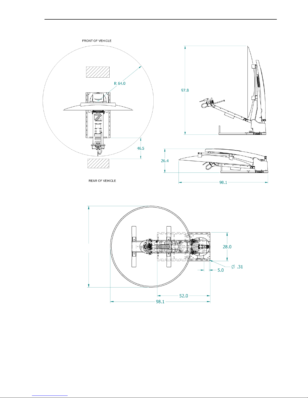
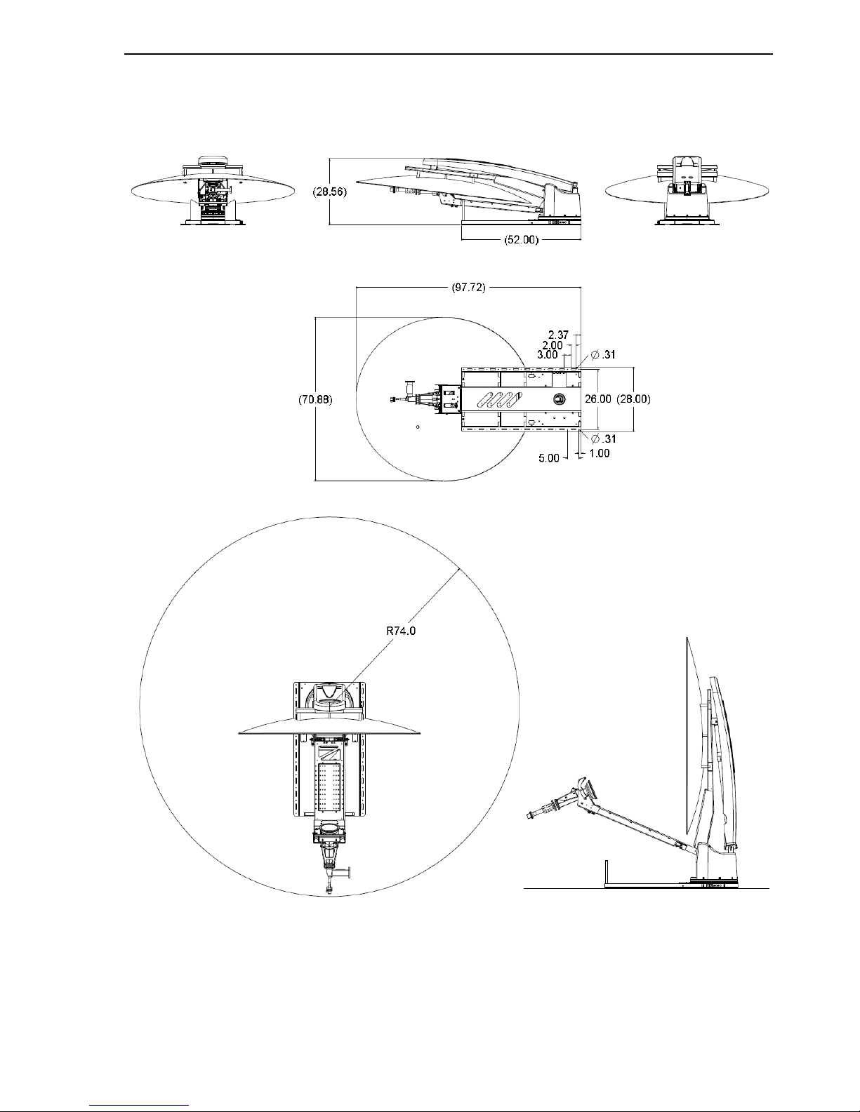
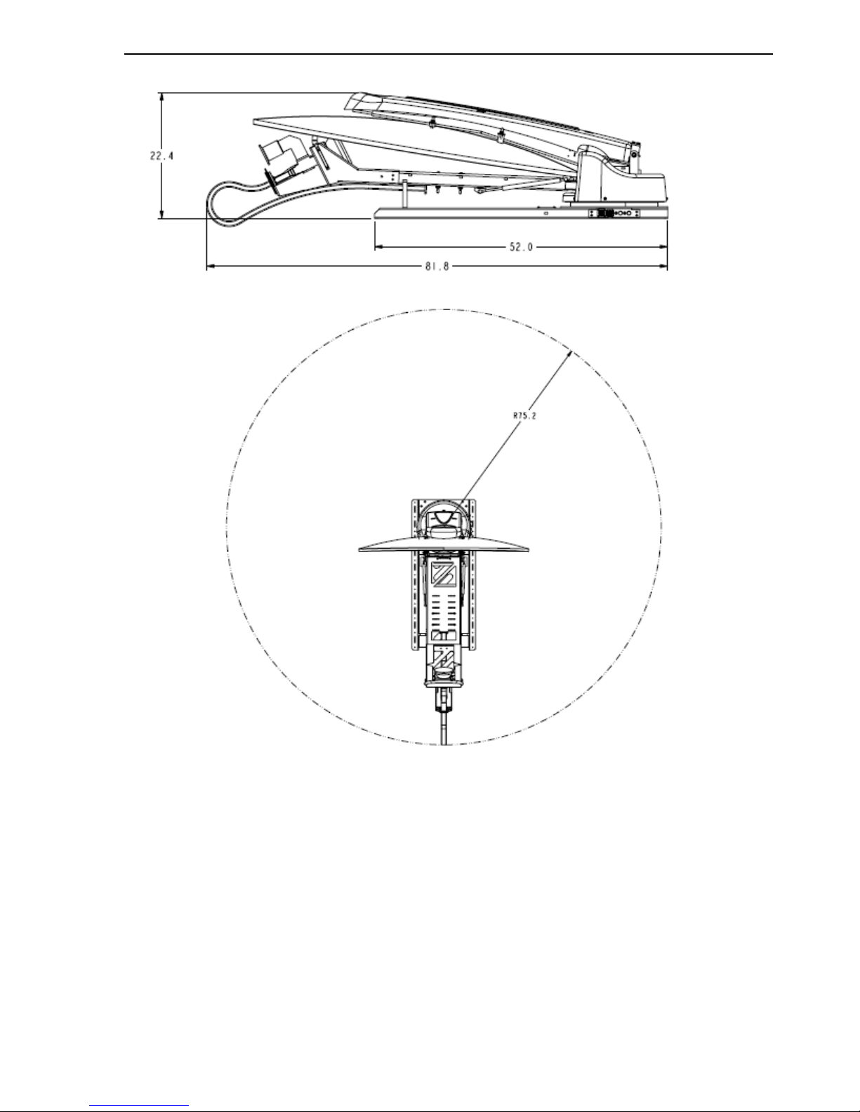
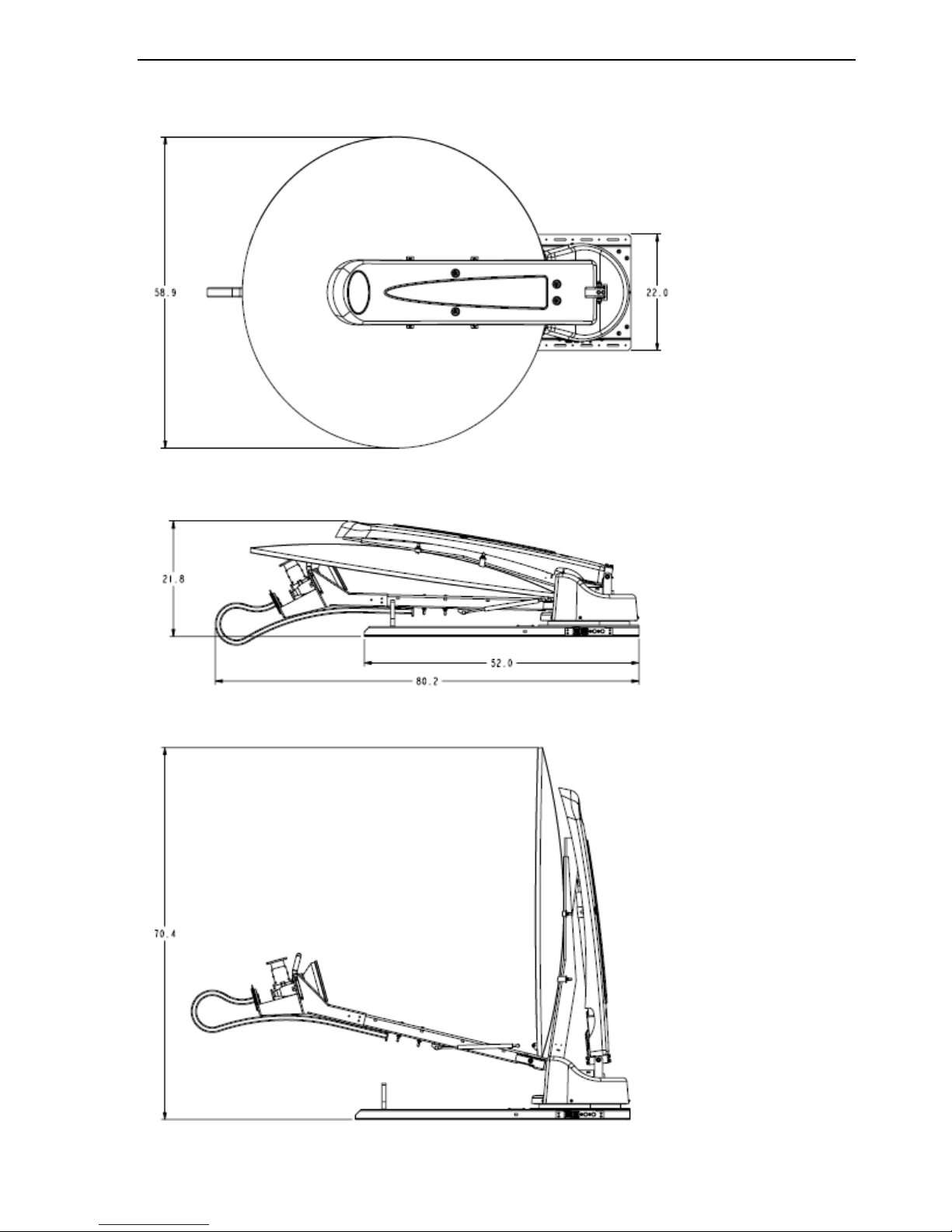
3.5.1 Clearance requirements for the iNetVu® 1800 Mobile Platforms
Fig. 2: Clearance requirements for the iNetVu® 1800 Mobile Platforms
71.5
iNetVu® Mobile Installation Manual Page 20 of 93
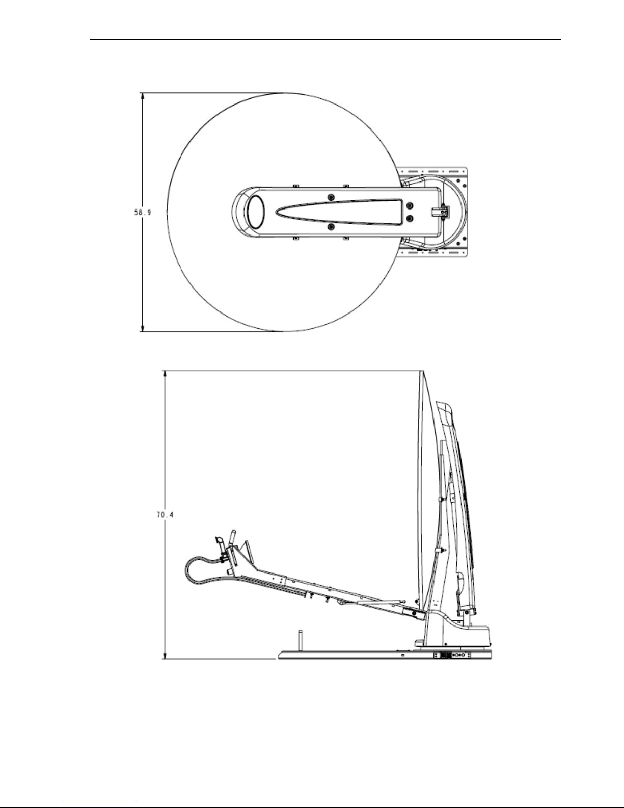
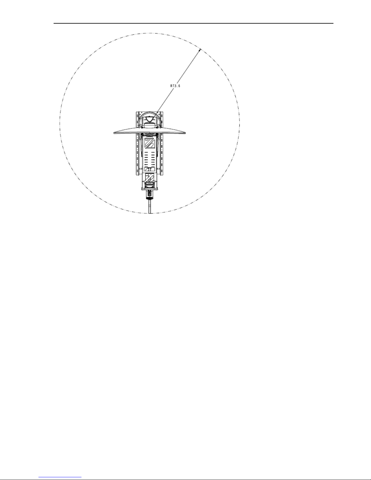
3.5.2 Clearance requirements for the iNetVu® 1800 C-Circular Band Platform
Fig. 3: Clearance requirements for the iNetVu® C-Circular Mobile Platform
iNetVu® Mobile Installation Manual Page 21 of 93
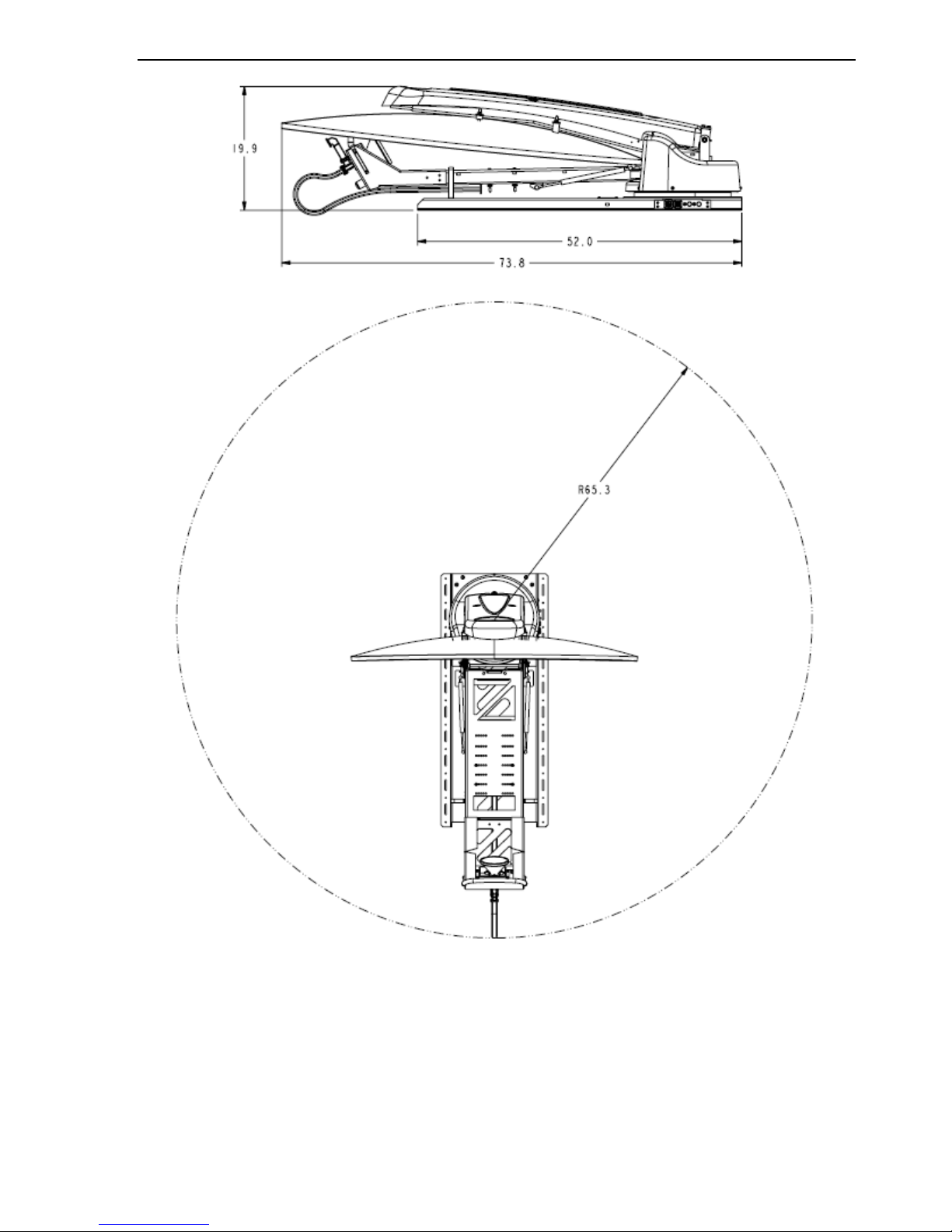
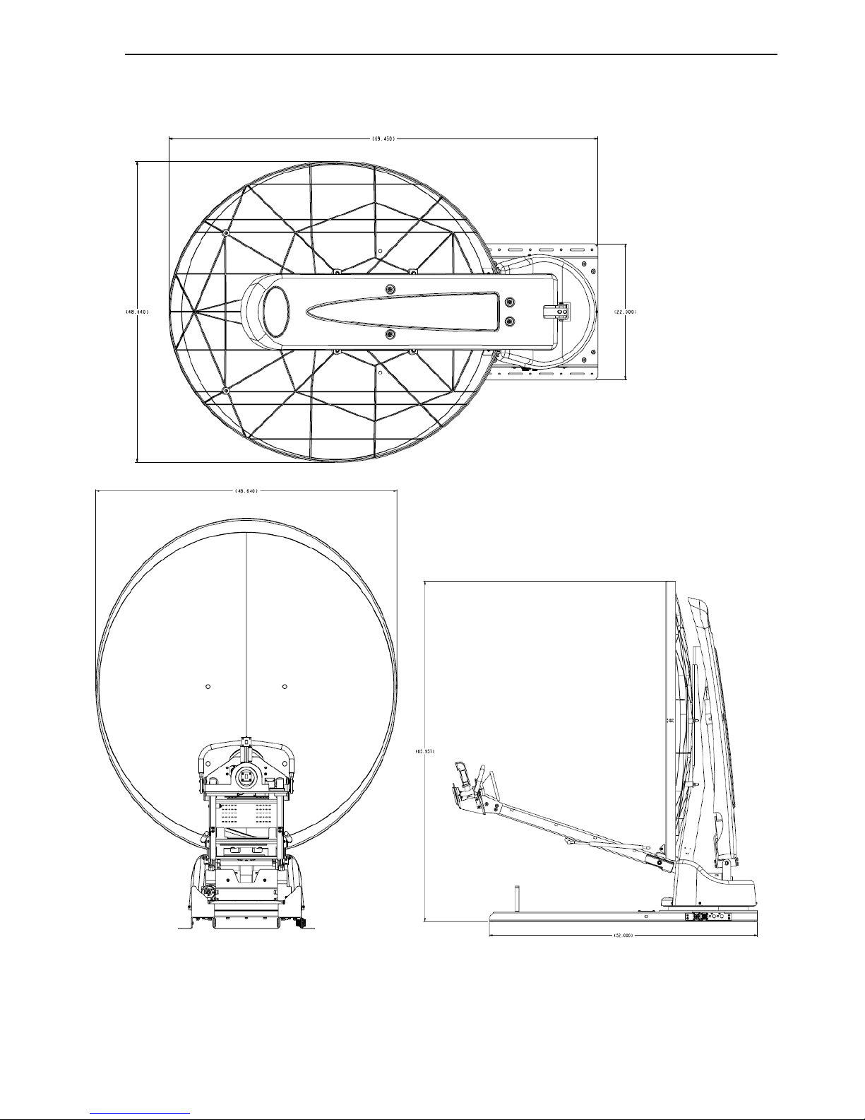
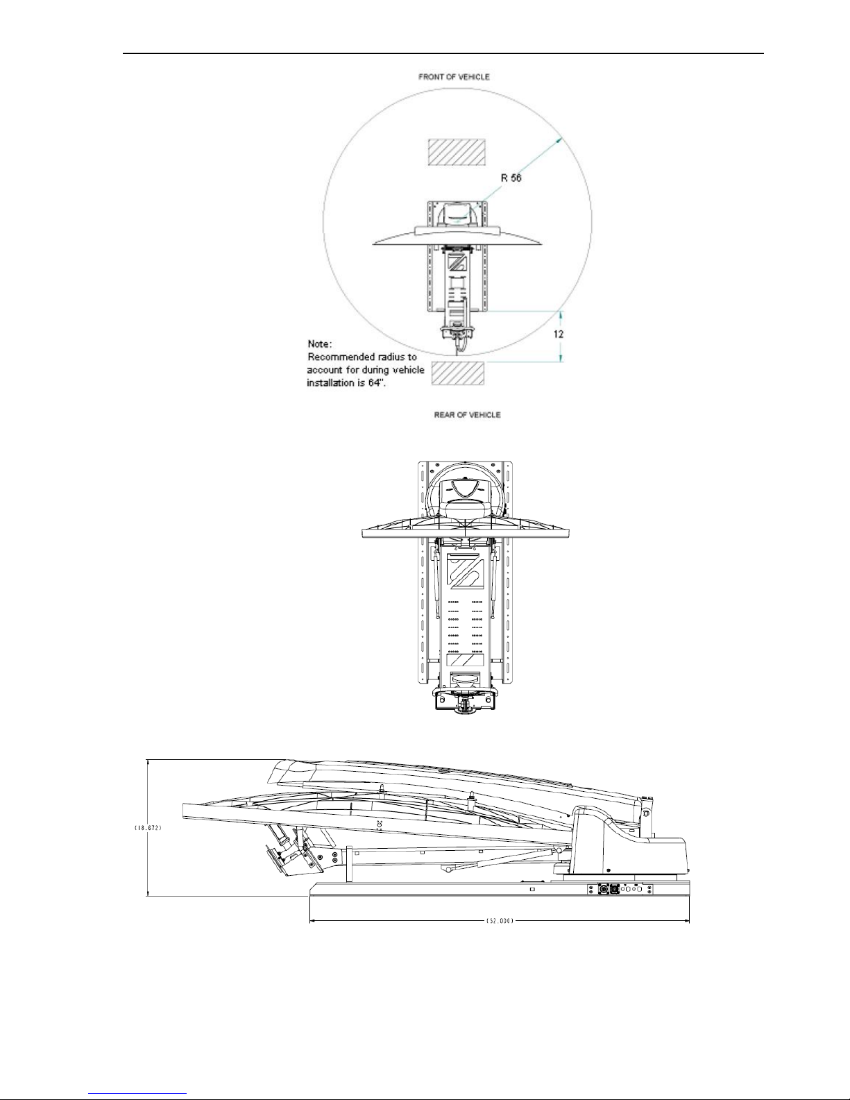
3.5.3 Clearance requirements for the iNetVu 1500 KU-Band Platform
iNetVu® Mobile Installation Manual Page 22 of 93
Fig. 4: Clearance requirements for the iNetVu® 1500 KU Band Mobile Platforms
iNetVu® Mobile Installation Manual Page 23 of 93
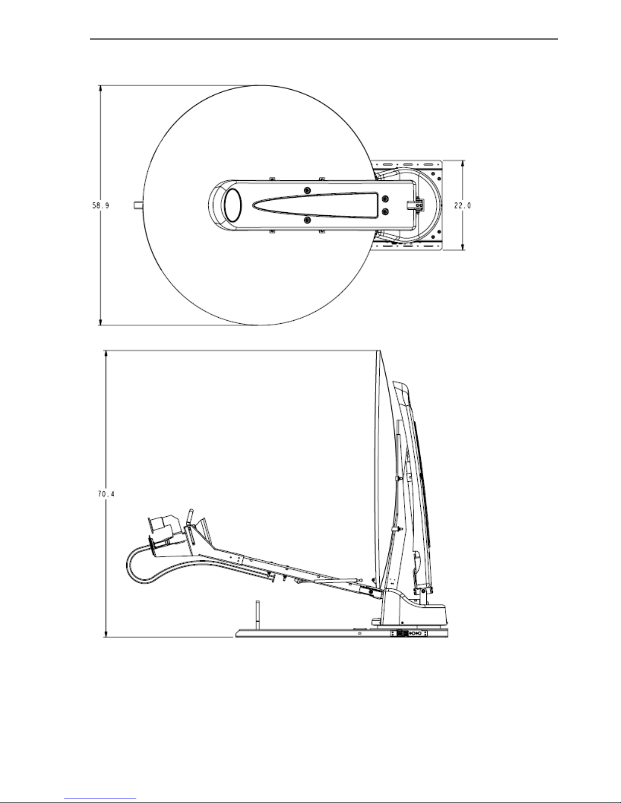
3.5.4 Clearance requirements for the iNetVu 1500 INSAT C-Band Platform
iNetVu® Mobile Installation Manual Page 24 of 93
Fig. 5: Clearance requirements for the iNetVu 1500 INSAT C-Band Platform
iNetVu® Mobile Installation Manual Page 25 of 93
3.5.5 Clearance Requirements for 1500 Standard C-Band Standard Linear Platform
iNetVu® Mobile Installation Manual Page 26 of 93
Fig. 6: Clearance requirements for the iNetVu 1500 C-Band Standard Linear Platform
iNetVu® Mobile Installation Manual Page 27 of 93
3.5.6 Clearance Requirements for the iNetVu 1200 Mobile Platform
Fig. 7: Clearance requirements for the iNetVu® 1200 Mobile Platforms
iNetVu® Mobile Installation Manual Page 28 of 93
Fig. 8: Clearance requirements for the iNetVu® 1200 Mobile Platforms
 Loading...