


iNetVu® 7000 Series Controller User Manual
With SW/FW 7.5.8.0
The iNetVu® brand and logo are registered trademarks of C-COM Satellite Systems, Inc.
© Copyright 2009 C-COM Satellite Systems, Inc.
1-877-iNetVu6
www.c-comsat.com
May 27, 2015
Revision 1.48

C-COM Satellite Systems Inc. Page 2 of 164
This page is intentionally left blank.
C-COM Satellite Systems Inc. Page 3 of 164
Copyright © 2009. All rights reserved. C-COM Satellite Systems Inc.
This document contains information, which is protected by copyright. All rights reserved.
Reproduction, adaptation, or translation without prior written permission is prohibited, except as
followed under the copyright laws.
Both the iNetVu® and C-COM names and logos are registered trademarks of C-COM Satellite
Systems Inc.
Intel® Pentium is a registered trademark of Intel Corporation. Microsoft, Windows, Windows NT
and MapPoint are registered trademarks of Microsoft Corporation.
All other product names mentioned in this manual may be trademarks or registered trademarks of
their respective companies and are the sole property of their respective manufacturers.

C-COM Satellite Systems Inc. Page 4 of 164
FCC and INDUSTRY CANADA INFORMATION TO THE USER:
The FCC and Industry Canada have imposed the following conditions when operating,
installing and deploying iNetVu® Mobile Earth Stations and is mandatory for all
installations made within the Continental United States and Canada as well as Hawaii,
Alaska, Puerto Rico, the U.S. Virgin Islands and other U.S. Territories. The FCC
requires that a certified installer perform the installation. It is also strongly recommended
that a qualified professional RV dealer/installer mount the system on your vehicle.
These conditions are also required by C-COM for all other installed locations.
All iNetVu® Mobile earth station installers must be C-COM Certified, and must have
specifically acknowledged the requirements for iNetVu® Mobile installations, which are
as follows:
1. “Installation” is the physical mounting and wiring of the Satellite provider’s earth
station on a vehicle or other stationary site in order to prepare for correct
operation. Only Certified C-COM iNetVu installers may perform the installation
and removal of an iNetVu® Mobile system.
2. “Deployment” means the raising, pointing and orienting of the earth station to the
communicating satellite, every time it is raised from a stowed position for use.
The deployment of an iNetVu® Mobile system must only be done by a trained
installer or by a consumer using the deployment software.
3. Installers shall install the iNetVu® systems only in locations that are not readily
accessible to children and in a manner that prevents human exposure to
potential radiation hazards.
4. For large vehicles with roof mounts, the height of the bottom lip of the earth
station when fully deployed must be at least six feet above the ground at all
times, or six feet above a surrounding surface which a person may easily access.
5. If a roof access ladder or any other means of access to the roof is installed on
the vehicle, then the ladder or access must be blocked by a suitable rope or
other barrier while the earth station is deployed or in operation. The installer
must provide this rope or barrier directly to the end user at the time of installation
and advise the user to use it at all times when the earth station is deployed or in
operation. Warning signs shall also be provided by the installer to the end user
to be posted on the improper installation or due to the failure to provide required
information to the end user.
6. Installers and end users will be deemed directly liable for any damages resulting
from either of their failure to comply with the above rules. These rules are meant
to ensure that extraordinary precautions and measures are used to prevent
satellite interference or exposure to harmful radiation. C-COM reserves the
rights to immediately suspend without liability or previous notice the
operation of the earth station upon detection of a deviation from its installation or
operational requirements until the deviation is corrected. In addition, C-COM
reserves the right to suspend or cancel the Installer Certificate of any installer
that has not fully complied with these installation requirements.

C-COM Satellite Systems Inc. Page 5 of 164
7. Further, the installer and end user may be directly liable for any damages
resulting from any change undertaken by either of them. Including but not limited
to, any modification of any part of the hardware, software, specific operational
frequencies, the authorized satellite, or the size or other characteristics of the
earth station supplied to them by C-COM or C-COM’s authorized
representatives. Warning signs shall be posted at prominent locations on the
earth station informing all persons of the danger of harmful radiation from the
earth station while it is deployed or while in operation.
8. The iNetVu® Mobile system may only be operated when the vehicle is stationary.
9. The installer must inform the end user that the vehicle must be stabilized during
the transmission, to prevent movement of the vehicle for any reason, including
movement of persons on or off the vehicle, or high winds. The installer shall
advise the end user how to appropriately stabilize their vehicle.
10. Installers shall be liable for all damages if they fail to comply with the above
mandatory conditions. This includes, but is not limited to damages caused by
improper installation or due to the failure to provide required information to the
end user.
Note 1:
This equipment has been tested and found to comply with the limits for a Class B digital
device, pursuant to Part 15 of FCC rules. These limits are designed to provide
reasonable protection against harmful interference when the equipment is operated in a
residential installation. This equipment generates, uses, and can radiate radio frequency
energy and, if not installed and used in accordance with this instruction manual, may
cause harmful interference with radio communications. However, there is no guarantee
that interference will not occur in a particular installation. If this equipment does cause
harmful interference to radio or television reception, which can be determined by turning
the equipment off and on, the user is encouraged to try to correct the interference by one
or more of the following measures:
Reorient or relocate the receiving antenna.
Increase the separation between the equipment and receiver.
Connect the equipment into an outlet on a circuit different from that to which the
receiver is connected.
Consult the dealer or an experienced radio / TV technician for help.
Note 2:
This Class B digital apparatus complies with Canadian ICES-003.

C-COM Satellite Systems Inc. Page 6 of 164
Table of Contents
1. Introduction ............................................................................................................ 9
2. Specifications ....................................................................................................... 10
3. Minimum Recommended PC Requirements....................................................... 10
4. Physical ................................................................................................................ 11
5. Typical Connection Configuration ...................................................................... 12
5.1. Typical Network Interface Connection ............................................................. 13
5.2. Typical USB Communication Interface ............................................................ 14
5.3. Typical Serial Communication Port Interface ................................................... 15
5.4. Typical Connection – PC Free......................................................................... 16
5.5. System Diagram with Splitter .......................................................................... 17
6. Installation ............................................................................................................ 18
6.1. Rack Installation .............................................................................................. 18
6.2. iNetVu® Software – Software and USB Driver Installation ............................... 18
6.3. iNetVu Setup Wizard ....................................................................................... 22
6.4. Setup .............................................................................................................. 24
6.5. Serial RS232 Setup ......................................................................................... 24
6.6. Existing iNetVu® Mobile Platform Installation ................................................... 25
7. iNetVu® Front Panel Operation ............................................................................ 27
7.1. LED Definition ................................................................................................. 27
7.2. Manual and Automatic Controls Button Operation ........................................... 28
7.3. LCD Screen and Navigator Keypad Operation ................................................ 29
7.4. Front Panel Menu Navigation Tree .................................................................. 30
7.5. Opening Screen .............................................................................................. 31
7.6. Main Menu ...................................................................................................... 31
7.6.1. MONITOR ................................................................................................ 32
7.6.1.1. MAIN ................................................................................................. 33
7.6.1.2. EL ..................................................................................................... 35
7.6.1.3. AZ ..................................................................................................... 36
7.6.1.4. PL ..................................................................................................... 37
7.6.1.5. GP .................................................................................................... 38
7.6.1.6. SM .................................................................................................... 38
7.6.1.7. S1 ..................................................................................................... 40
7.6.1.8. S2 ..................................................................................................... 41
7.6.1.9. MB .................................................................................................... 42
7.6.1.10. IP ...................................................................................................... 43
7.6.1.11. GW ................................................................................................... 43
7.6.2. OPERATION ............................................................................................ 44
7.6.3. CONF1 ..................................................................................................... 48
7.6.3.1. Password Protection ......................................................................... 48
7.6.3.2. Configuration Menu (CONF1) ........................................................... 48
7.6.3.3. S1 ..................................................................................................... 49
7.6.3.4. SM1 .................................................................................................. 51
7.6.3.5. SM2 .................................................................................................. 52
7.6.4. CONF2 ..................................................................................................... 52
7.6.4.1. Configuration Menu (CONF2) ........................................................... 53
7.6.4.2. S2 ..................................................................................................... 54
7.6.4.3. MB .................................................................................................... 56
7.6.4.4. EL ..................................................................................................... 57
7.6.4.5. AZ ..................................................................................................... 59
7.6.4.6. PL ..................................................................................................... 61

C-COM Satellite Systems Inc. Page 7 of 164
7.6.4.7. GP .................................................................................................... 62
7.6.4.8. C1 ..................................................................................................... 63
7.6.4.9. C2 ..................................................................................................... 66
7.6.4.10. C3 ..................................................................................................... 69
7.6.4.11. SG .................................................................................................... 70
7.6.4.12. IP ...................................................................................................... 70
7.6.4.13. SR ..................................................................................................... 71
7.6.5. TST .......................................................................................................... 72
7.6.5.1. E&A&P .............................................................................................. 73
7.6.5.2. DPY .................................................................................................. 74
7.6.5.3. DPYQ ............................................................................................... 75
7.6.5.4. DPY_C .............................................................................................. 75
7.6.5.5. CP ..................................................................................................... 76
7.6.5.6. A_ACP .............................................................................................. 77
7.6.5.7. M_ACP ............................................................................................. 77
7.6.5.8. S_ACP .............................................................................................. 77
7.6.6. INFO ........................................................................................................ 77
7.6.6.1. CC1 .................................................................................................. 78
7.6.6.2. CC2 .................................................................................................. 78
7.6.6.3. DVB_D .............................................................................................. 79
7.6.6.4. DVB_P .............................................................................................. 79
7.6.6.5. MOD ................................................................................................. 79
7.6.6.6. SYS1 ................................................................................................ 80
7.6.6.7. ERR .................................................................................................. 80
8. iNetVu® 7000 Series Software .............................................................................. 81
8.1. Setup Wizard .................................................................................................. 81
8.2. Navigating Menus ........................................................................................... 82
8.2.1. iNetVu Controls ........................................................................................ 82
8.2.2. Maintenance ............................................................................................ 94
8.2.2.1. Platform Parameters ......................................................................... 95
8.2.2.2. GPS and Compass ........................................................................... 96
8.2.2.3. Elevation Parameters ...................................................................... 100
8.2.2.4. Azimuth Parameters ........................................................................ 102
8.2.2.5. Polarization Parameters .................................................................. 104
8.2.2.6. PC Application ................................................................................ 106
8.2.2.7. Site Name and Controller Beep ....................................................... 106
8.2.2.8. Maintenance Menu Buttons ............................................................. 107
8.2.3. Configuration .......................................................................................... 109
8.2.3.1. Target Satellite Parameters ............................................................. 110
8.2.3.2. Reference Satellite Parameters ...................................................... 113
8.2.3.3. Modem Parameters......................................................................... 114
8.2.3.4. Beacon receiver .............................................................................. 117
8.2.3.5. Controller Parameters ..................................................................... 118
8.2.3.6. Search Parameters ......................................................................... 119
8.2.3.7. Controller Feature ........................................................................... 123
8.2.3.8. Advanced Search Configuration ...................................................... 125
8.2.3.9. LNB LO & 22KHz Tone ................................................................... 126
8.2.3.10. COM Port Interface ......................................................................... 127
8.2.3.11. Configuration Menu Buttons ............................................................ 127
8.2.3.12. Maintenance Test ........................................................................... 128
8.2.4. About ..................................................................................................... 130
8.2.5. Language ............................................................................................... 133

C-COM Satellite Systems Inc. Page 8 of 164
8.2.6. Exit ......................................................................................................... 133
9. iNetVu® 7000 Series Controller Web Interface.................................................. 134
9.1. Navigating Menus ......................................................................................... 134
9.2. Controls ........................................................................................................ 136
9.3. Configuration ................................................................................................. 137
9.4. System Test .................................................................................................. 138
9.5. About ............................................................................................................ 139
9.6. Firmware/Satellite Table Update ................................................................... 140
9.6.1. Firmware Update ................................................................................... 141
9.6.2. Satellite Table Update ............................................................................ 142
10. Controller Connectivity .................................................................................. 143
10.1. Network Configuration Example ................................................................ 144
10.2. How to Set Network Configurations on your PC ......................................... 145
11. Integrations and Compatibility Features ....................................................... 146
11.1. GLONASS Navigation System ................................................................... 146
11.2. Uplogix Remote Management ................................................................... 146
12. APPENDICES .................................................................................................. 147
12.1. Appendix 1: Default Limits and Configuration Data Tables ........................ 148
12.2. Appendix 2: Compass Direction and System Ref. AZ Table ...................... 151
12.3. Appendix 3: LCD Table Summary .............................................................. 152
12.4. Appendix 4: Router Configuration Example ............................................... 156
12.5. Appendix 5: Tooway Look-up Table ........................................................... 157
12.6. Appendix 6: DC Input Power Cable Connectivity ....................................... 161
12.7. Appendix 7: Declaration of Conformity ....................................................... 163
Proprietary Notice: This document contains information that is proprietary and
confidential to C-COM Satellite Systems, Inc., and is intended for internal and or
C-COM Satellite Systems Inc. authorized partners use only. No part of this
document may be copied or reproduced in any way, without prior written
permission of C-COM Satellite Systems, Inc.

C-COM Satellite Systems Inc. Page 9 of 164
1. Introduction
The iNetVu® 7000 Series Controller is a one-box, one-touch solution for satellite autoacquisition. Designed to interface with a number of Satellite Modems, iNetVu® VSATs,
and DVB-S/DVB-S2ACM Receivers, the iNetVu® 7000 Series Controller is an easily
configurable and operated antenna controller unit which now comes with the combined
GPS/GLONASS Satellite Navigation System.
Fig. 1: iNetVu® 7000 Series Controller
The iNetVu® 7000 Series Controllers are fully functional and configurable straight out of
the box solution. No PC or monitor required. An I/O GLONASS/GPS Module inside and
the capability to connect an external GLONASS/GPS device via serial port, a DVBS2ACM/CCM Tuner, an onboard LCD displaying real-time system status, and a Keypad
Navigator, makes using the iNetVu® 7000 Series Controller extremely simple.
The iNetVu® 7000 Series Controllers along with any iNetVu® platform can work as a
complete stand-alone unit. No modem or RF splitters are required for satellite
acquisition. The LNB can be powered straight from the controller.
Equipped with a 32-Bit Micro-Controller, the iNetVu® 7000 Series Controllers obtain
extremely precise readings from all axes resulting in quicker and more reliable satellite
acquisition time.
The 7000 Series Controllers are compatible with iNetVu® legacy systems in the field.
Existing users can easily upgrade to this new line of controllers.

C-COM Satellite Systems Inc. Page 10 of 164
2. Specifications
Dimensions: Width: 17.1” x Depth: 11.0” Height: 2.0”
Weight: 9.9 lbs. (4.5 kg)
Operating Temperature: -20°C to +50°C
Elevation Output: 12VDC, 15A (Max.)/24 VDC, 8A
Azimuth Output: 12VDC, 10A (Max.)/24 VDC, 6A
Polarization Output: 12VDC, 3A (Max.)/24 VDC, 2A
Power Consumption (Idle): 12VDC @ 1A /24 VDC @ 0.5A
Universal AC Input: 100 – 240 VAC, 2.2 – 1.1 A, 50/60 Hz
Motor Control Connector: 9 Position Circular AMP Connector
Signal Input: Female DB26 Connector
GPS Connector: SMA (Sub-Miniature Version A)
Rx Connector: Type F RG6
PC Interface: USB Interface
Network Interface
Serial Interface
Web Interface
Front Panel Interface: Automatic and Manual Control Keypad
LCD Screen and Keypad Navigator
Tuner Specifications
RF Input Range: 950MHz to 2150MHz
Input Signal Level: -65dBm to –25dBm
Input/Output Impedance: 75 Ω
Symbol Rate: ~1 to 45Msps
**NOTE** Controller specifications include/cover model 7000B, 7000C, 7024A,
7024B and 7024C
3. Minimum Recommended PC Requirements
Operating System Windows XP, Vista, W7 and W8
CPU 2.0 GHZ
Memory (RAM) 1.0GB
MSN.Net Framework 3.5 installed
GPS
GPS
Antenna
Interface
LCD Screen
Automatic
Control
Buttons
Manual Control
Buttons
Front Panel
LEDs
Keypad Navigator
Reset
Button
LAN
Network
Interface
SENSORS
26-pin
Interface
for Sensor
Cable
MOTOR
&
POWER
9-Position
Interface for
Motor Control
Cable
Power Input
90-264 VAC
Power Input
and Switch
USB
USB
Interface
RX OUT
Additional Receive
Signal output
RX IN
Receive Signal
from iNetVu
Mobile Platform
12/24 VDC
Power Input
External VDC
Power Input
Ground
protection
External
grounding
connection
Serial port
Serial Port
Interface
COOLING
FANS
Air Ventilation
C-COM Satellite Systems Inc. Page 11 of 164
4. Physical
Fig. 2: iNetVu® 7000 Series Front and Rear Panel
Note: VDC Power Input feature is available in the 7000C and 7024C Models Only.
See Appendix for VDC power input external cable connectivity wiring.

This situation or practice might result in property or
equipment damage. Ensure Sensor and Motor cables
are connected prior to powering on 7000 Series
Controller. Do not connect or disconnect cables once
controller has been powered on. It is recommended
that controller is properly grounded at all times
C-COM Satellite Systems Inc. Page 12 of 164
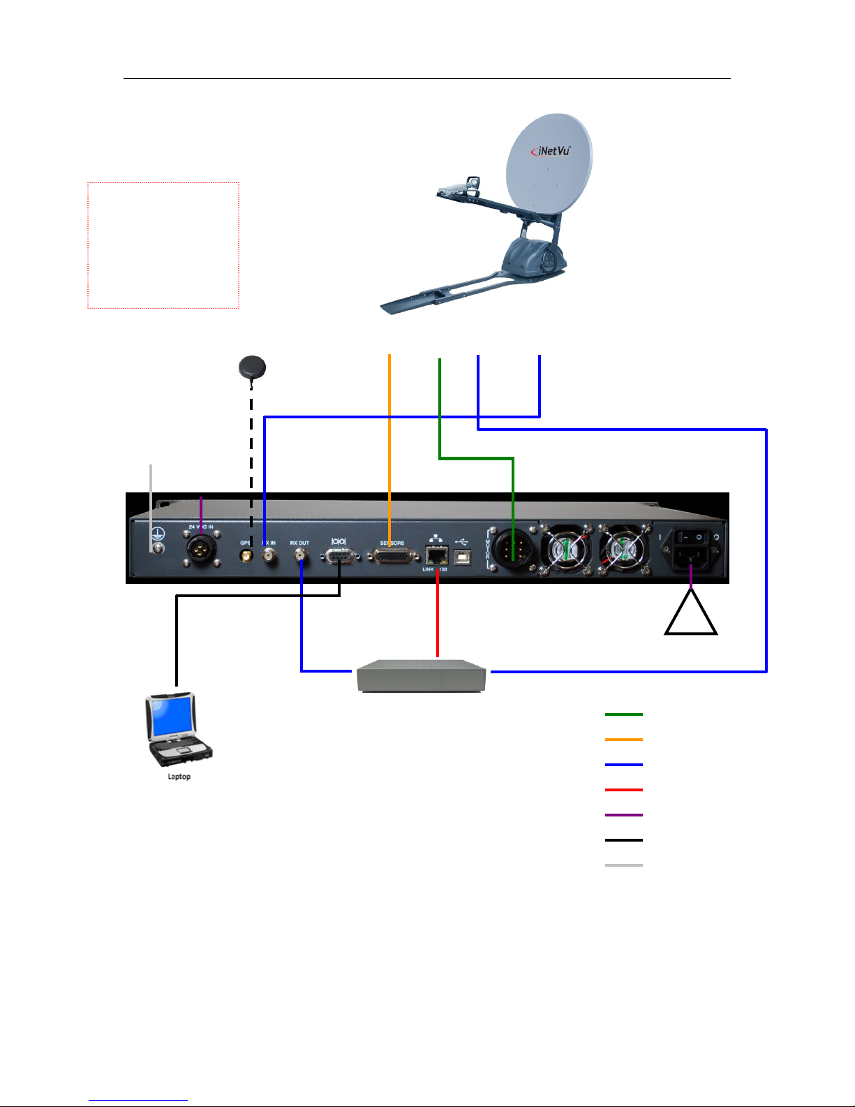
5. Typical Connection Configuration
The typical connection configuration for each service will be the same regardless of the
Satellite Modem / VSAT. However, the configuration parameters for Satellite Modem /
VSAT Communication will differ depending on service. See iNetVu® System Manual for
configuration procedures corresponding to the service used.
NOTE: The 7000C/7024C controllers must use the GLONASS/GPS antenna that
was shipped with the system for optimal GPS signal reception.
RX IN
GPS/Glonass
Antenna
1201 iNetVu™
Mobile Platform
MOTOR
CONTROL
TX
Satellite Modem / VSAT
!
100 - 260VAC
TX OUT
RX IN
SENSOR
CABLE
RX
RX OUT
* Ground Connection
RG6 Coaxial Cable
Network Cable
Power Cable
Sensor Cable
Motor Control Cable
* Ground Connection
*Ground
protection
External
grounding
connection
12/24 VDC
Power Input
7000C/7024C
must use the
GLONASS/GPS
antenna that was
shipped with the
controller.
C-COM Satellite Systems Inc. Page 13 of 164
5.1. Typical Network Interface Connection
Fig. 3: iNetVu® 7000 Controller Typical Connection Configuration
*Recommended for proper grounding of iNetVu® systems.
Note: VDC Power Input feature is available in the 7000C and 7024C Models Only. See Appendix for
VDC power input external cable wiring.
GPS
Antenna
MOTOR
CONTROL
TX
Satellite Modem / VSAT
TX OUT
RX IN
SENSOR
CABLE
100 – 260VAC
Network Cable
USB Cable
RX
RX
RX OUT
*Ground
protection
External
grounding
iNetVu™ Mobile
Platform
RG6 Coaxial Cable
Network Cable
Power Cable
Sensor Cable
Motor Control Cable
USB Cable
* Ground Connection
12/24 VDC
Power input
7000C/7024C
must use the
GLONASS/GPS
antenna that was
shipped with the
controller.
C-COM Satellite Systems Inc. Page 14 of 164
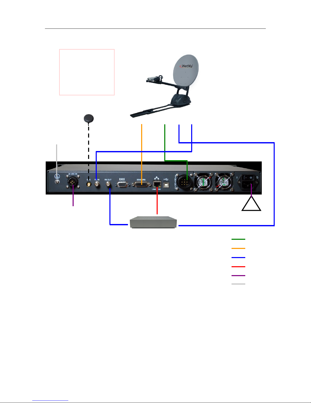
5.2. Typical USB Communication Interface
Fig. 4: USB Configuration Interface
*Recommended for proper grounding of iNetVu® systems.
Note: VDC Power Input feature is available in the 7000C and 7024C Models Only. See Appendix for
VDC power input external cable wiring.
Satellite Modem / VSAT
iNetVu™ Mobile
Platform
SENSOR
CABLE
MOTOR
CABLE
100 - 260VAC
RX
TX
RX IN
RX OUT
Serial Port
RS232
TX Out
RX IN
GPS/Glonass
Antenna
Network Cable
*Ground
protection
External
grounding
connection
RG6 Coaxial Cable
Network Cable
Power Cable
Sensor Cable
Motor Control Cable
Serial Cable
* Ground Connection
12/24 VDC
Power input
7000C/7024C
must use the
GLONASS/GPS
antenna that was
shipped with the
controller.
C-COM Satellite Systems Inc. Page 15 of 164
5.3. Typical Serial Communication Port Interface
Fig. 5: Serial RS232 Configuration Interface
*Recommended for proper grounding of iNetVu® systems.
Note: VDC Power Input feature is available in the 7000C and 7024C Models Only. See Appendix for
VDC power input external cable wiring.
100 - 260VAC
GPS/Glonass
Antenna
MOTOR
CONTROL
SENSOR
CABLE
Satellite Modem / VSAT
RX OUT
Network
Cable
RX IN
TX
RX
TX OUT
RX IN
*Ground
protection
External
grounding
connection
iNetVu™ Mobile
Platform
12/24 VDC
Power input
7000C/7024C
must use the
GLONASS/GPS
antenna that was
shipped with the
controller.
Motor Control Cable
RG6 Coaxial Cable
Network Cable
Power Cable
Sensor Cable
* Ground Connection
Motor Control Cable
C-COM Satellite Systems Inc. Page 16 of 164
5.4. Typical Connection – PC Free
Fig. 6: iNetVu® 7000 Series Controller PC Free Connection Configuration
*Recommended for proper grounding of iNetVu® systems.
Note: VDC Power Input feature is available in the 7000C and 7024C Models Only. See Appendix for
VDC power input external cable wiring.
RX
GPS /Glonass
Antenna
iNetVu™ Mobile
Platform
MOTOR
CONTROL
TX
Satellite Modem / VSAT
100 - 260VAC
TX OUT
RX
SENSOR
CABLE
**If the splitter option is
used, ensure the LNB
Power is disabled in the
7000 Series Controller.
(See section 8.1.3.1 – “LNB
Power” for more detail)
RX IN
*Ground
protection
External
grounding
connection
12/24 VDC
Power input
7000C/7024C
must use the
GLONASS/GPS
antenna that was
shipped with the
controller.
RG6 Coaxial Cable
Network Cable
Power Cable
Sensor Cable
Motor Control Cable
* Ground Connection
C-COM Satellite Systems Inc. Page 17 of 164
5.5. System Diagram with Splitter
**Please Note: Using a splitter is optional. If the user does not wish to power the LNB
from the Controller, a splitter must be used such that power is passed to the LNB from
the VSAT Modem (or alternate power source).
Fig. 7: iNetVu® 7000 Series Controller with Splitter Configuration
*Recommended for proper grounding of iNetVu® systems.
Note: VDC Power Input feature is available in the 7000C and 7024C Models Only. See Appendix for
VDC power input external cable wiring.

C-COM Satellite Systems Inc. Page 18 of 164
6. Installation
The iNetVu® 7000 Series Controllers are shipped pre-configured and calibrated with the
iNetVu® Mobile Platform and service which you plan to use. Only configuration of the
Satellite Modem / VSAT Communication parameters and the satellite you wish to find is
required.
***Note: controllers may have 4 or 5 digit serial number which is required to be entered
for correct default configuration values.
6.1. Rack Installation
The iNetVu® 7000 Series Controllers include attachable “ears” which make the iNetVu®
7000 Series Controllers configurable for rack-mounted installation.
If you are installing the iNetVu® 7000 Series Controller onto a rack, ensure that you use
supporting rails or a shelf to support the weight of the iNetVu® 7000 Series Controller,
and use the provided “ears/brackets” to fasten the unit to the rack face.
6.2. iNetVu
It is recommended that the previous software be uninstalled before installing latest
software version if upgrading. See minimum recommended pc requirements for most
favorable working system.
Note: The application will exit if controller communication is via USB and Modem
Configuration Type is set to HN_KA during any power recycle or loss of
communication (cable unplugged) without warning. This will NOT hold true if
controller is in Firmware update mode. More info under Maintenance Menu
Buttons section.
®
Software – Software and USB Driver Installation
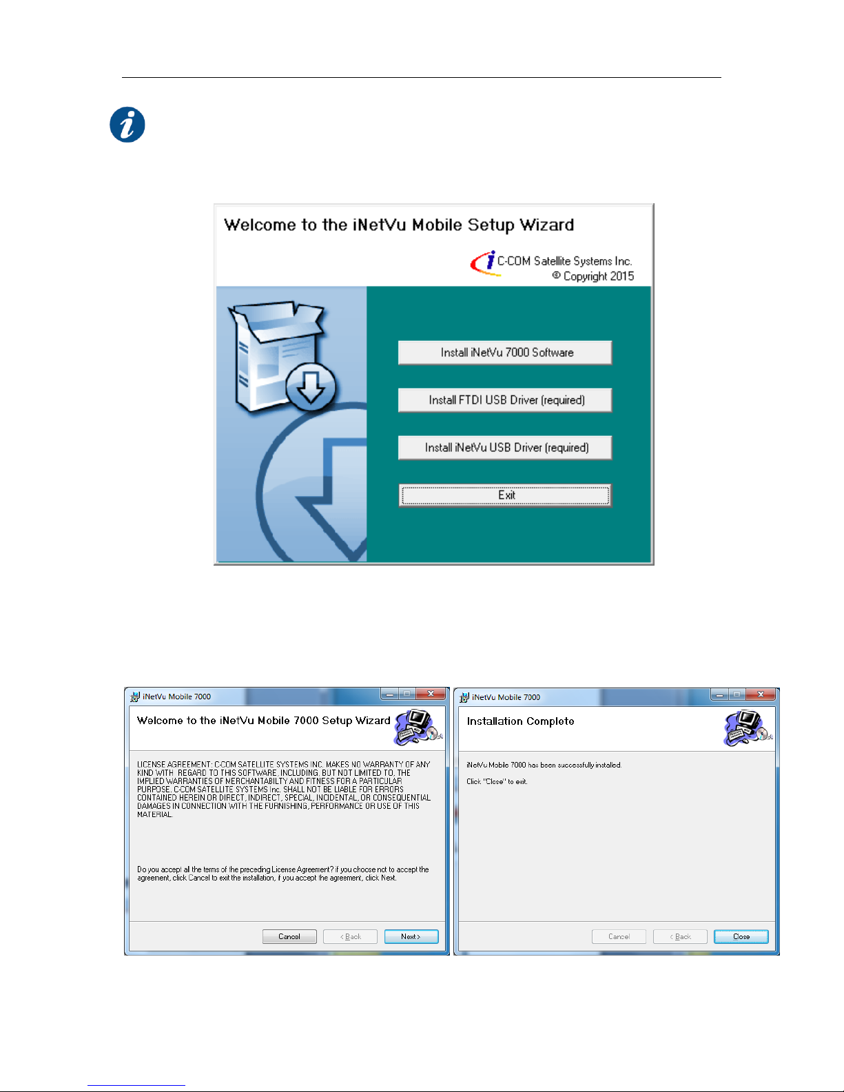
C-COM Satellite Systems Inc. Page 19 of 164
Please Note: Do not connect the Controller via USB until the drivers and software
have been installed
1. Install the software from the Memory Stick or from a downloaded file by double
clicking on iNetVuSetup.exe and follow the installation wizard.
Note: The Driver installation will be done in two stages. FTDI CDM Drivers and,
USB Drivers.
2. Install the iNetVu 7000 Software and close when complete.
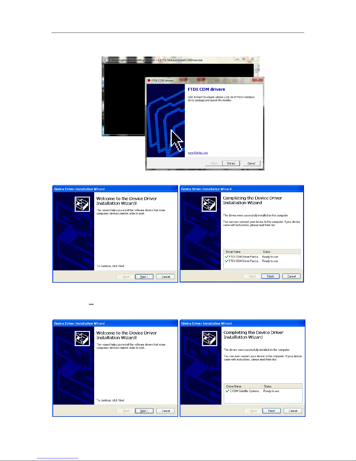
C-COM Satellite Systems Inc. Page 20 of 164
3. Install the FTDI USB Drivers and iNetVu USB Drivers. Both are required.
Click “Extract”
Click “Next” Click “Finish”
4. Click Next on “Device Driver installation Wizard” window. Two windows may
appear one for FTDI and one for Legacy click Next on both.
Click “Next” Click “Finish”
C-COM Satellite Systems Inc. Page 21 of 164
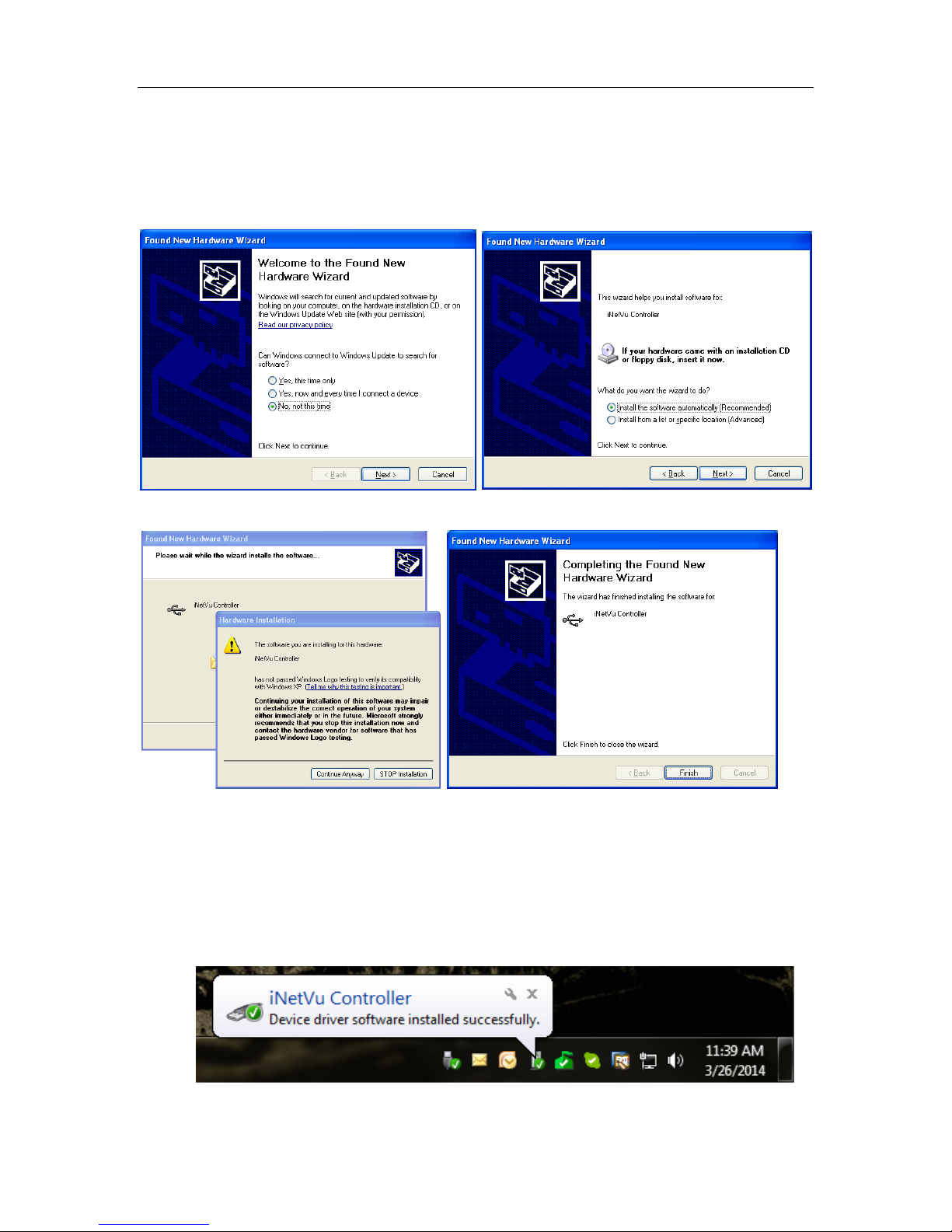
5. Now that the drivers and software package has been installed, connect the
iNetVu 7000 Controller via USB to your PC.
6. Windows XP users will have to follow the new hardware wizard and let windows
automatically install the drivers.
Select “No, not this time” Select “Install the software automatically”
Click “Continue Anyway” Click “Finish”
7. Now that the drivers and software package has been installed, connect the
iNetVu 7000 Controller via USB to your PC.
8. Windows Vista and 7 users, the drivers should install automatically without any
further user action when the controller is powered up.
C-COM Satellite Systems Inc. Page 22 of 164
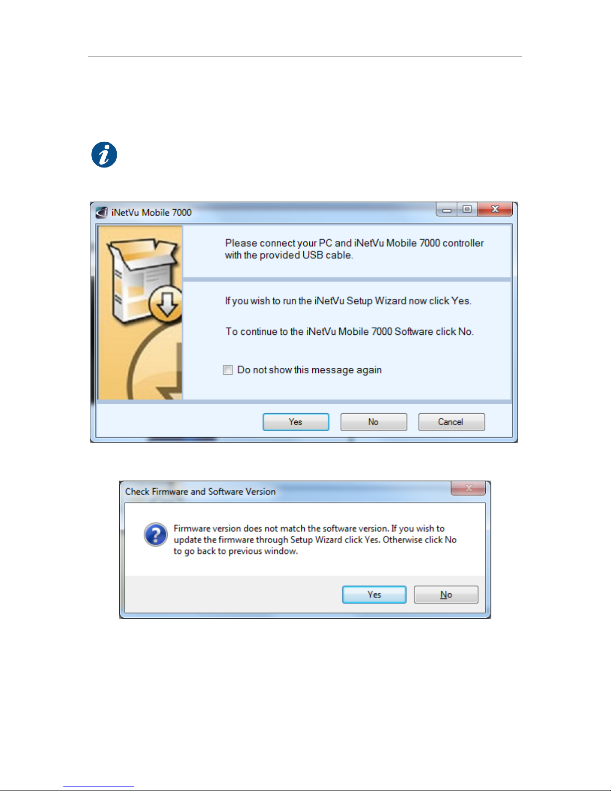
6.3. iNetVu Setup Wizard
1. The first screen you will see is the new iNetVu Setup Wizard. You can choose to
continue using the wizard or click NO to proceed to the iNetVu Mobile 7000 software.
NOTE: It is recommended that you continue to the iNetVu Setup Wizard and
confirm all required information is correct. Please select “Do not show this
message again” so this pop-up will not appear after you have completed the
initial Controller setup.
2. If the controller firmware does not match you will be prompted to update.
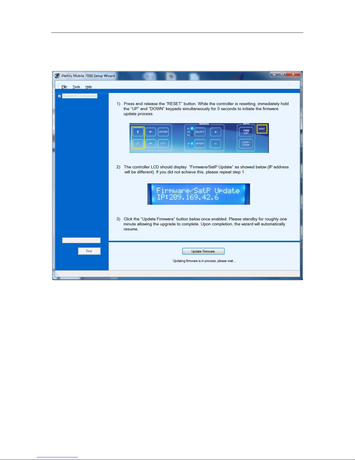
C-COM Satellite Systems Inc. Page 23 of 164
3. Follow the on screen instructions to update the controller firmware. Once
complete the wizard will resume.
4. You may wish to continue through the wizard to complete the controller configuration or
verify the settings. You can switch to the iNetVu software at any time by right clicking and
selecting Controls.

C: PC---9600 T__O: +0.0
N985A—2.X-12209
C-COM Satellite Systems Inc. Page 24 of 164
6.4. Setup
1. Connect all of the cables and components as depicted by the previous section
(setup Diagrams). Select connections that are best suited for your application.
2. Power on the iNetVu® 7000 Series Controller.
3. Set your external PC IP on the same subnet as the iNetVu® 7000 Series
Controller (Default controller IP Address of the 7000 is 192.168.0.2)
4. Refer to the appropriate User Manual for service based system configuration
5. Controller should be power cycled after each and every configuration change.
6.5. Serial RS232 Setup
1. Power ON the controller and connect the RS232 cable from the PC to the
Controller.
2. Refer to section 5.3 (RS232 setup diagram) before continuing with the RS232
serial port connection.
3. Set the C2 option in the controller to PC---9600, to do this advance to CONF2
option on the controller key pad and depress ENTER button; in the password
field enter the password, if this was changed from the default. If default password
has not been changed press up ↑ arrow followed by the ENTER button.
4. Navigate to the C2 menu option and press the ENTER button.
5. Using the up ↑ arrow button change the C: option to read C: PC---9600 press
ENTER.
Fig. 8: C2 Screen from Configuration for RS232 Communication
Press the EXIT button 2 times, you will receive a prompt to save the configuration
select Y for yes and press ENTER. The setting change has been completed on the
controller side which will automatically update within the software.
6. Launch the Application Software from your computer.
7. Advance to the Configuration window, browse down to the COM Port Interface
section and ensure that the Interface option is set to PC, the BAUD rate is set to
C-COM Satellite Systems Inc. Page 25 of 164
9600 and the COM Port is set to COM1 in PC Application section On the
Maintenance window.
Fig. 9: Configuration for controller RS232 serial options
8. The iNetVu® 7000 Series Controller is now set to communicate via RS232 serial
connection.
**Note: as a rule of thumb you should always be running the latest iNetVu Firmware
version (version 7.5.8.0+ or greater) to get full functionality of the features. In some
cases the latest boot loader (7.6.1.0 at time of document creation) is also required to
compliment the software features.
6.6. Existing iNetVu
®
Mobile Platform Installation
If you are replacing an existing iNetVu® Controller with Newer iNetVu® 7000 Series
Controller, you will need to perform an Azimuth and Polarization Calibration (PL
Calibration NOT required on platforms with Tilt Sensors 980/1200 version 3.0+ or 1800
version 2.0+ and all new generation platforms) and set the iNetVu® Mobile Platform
Serial Number prior to searching for satellite.
LCD Method
1. Advance to the Operations menu using the ‘←’ and ‘→’ arrows on the keypad.
2. Advance to “AZC” using the ‘←’ and ‘→’ arrows and press the “Enter” key on the
keypad. IMS will begin the Azimuth Calibration Function. Verify that there are no
obstructions that would impede a full Azimuth sweep.
3. After this is complete, go back to the Operations menu by pressing the “Exit”
button to navigate backwards.
4. Advance to “PLC” using the arrows and select the “Enter” key on the keypad.
IMS will begin the Polarization Calibration Function. Verify that there are no
obstructions that would impede a full Polarization sweep. “PLC” is not valid with
some iNetVu® Mobile Platform and thus may be skipped.
5. After this is complete, navigate to the “Conf2” menu from the keypad. The “Exit”
button on the keypad can be used to navigate back to the original menu, and the
“Enter” button will allow the user to enter into a menu. (default Conf1 menu
access password “password”)
C: PC---9600 T__O: +0.0
A12B—2.X-10351
C-COM Satellite Systems Inc. Page 26 of 164
6. Navigate to “C2” in the configuration menu and select the “Enter” button on the
keypad.
7. A screen containing Console Port, Platform Type, Platform Version and Serial
Number Data will appear. Navigate to the far bottom right section of the screen
where the platform description appears (i.e. A12B for 1.2 mobile unit), and click
on the ‘↑’ arrow once. This action will allow you to make modifications to that
section.
Fig. 10: C2 Screen from Configuration
8. Next to the dish size (i.e. A12B, etc.), there exists a platform hardware version
followed by 4/5-digit platform serial number as outlined in the figure above.
Change version number and the iNetVu® Platform Serial Numbers by using the
‘→’ to advance between digits, and the ‘↑’ or ‘↓’ to change the value of the digit.
The iNetVu® Mobile Platform Serial Number and Hardware Version will be found
on your iNetVu® Mobile Platform ONLY the LAST 5 DIGITS need be entered for
the Serial No. Older systems may have ONLY 4 DIGITS.
Note: When configuring iNetVu
®
system you must enter serial number first
then select platform type, not following this priority order may result in
inaccurate values.
9. Click the “Enter” button on the keypad once the serial number has been entered,
and exit the configuration menu by click the “Exit” button twice. One time to
return to the configuration screen and one more time to exit the configuration
screen.
10. Once prompted if you would like to save the configuration, press the ‘↑’ button
such that ‘Y’ is selected for “yes”, and press, “Enter”.
That’s it. You have successfully completed the installation and setup of the iNetVu®
7000 Series Controller and are ready to find satellite.

C-COM Satellite Systems Inc. Page 27 of 164
7. iNetVu® Front Panel Operation
7.1. LED Definition
Fig. 11: iNetVu® 7000 Series Controller Front Panel LED Panel
POWER
Solid light indicates power is ON.
MOTOR
Flashes when any of the three motors are instructed to move.
COMM / LOCK
Indicates Communication between Controller and Modem, it also indicates communication
between GPS and controller. NA must be selected when checking GPS communication status.
Slow blinking (2 sec. intervals) indicates no communication.
Slow blinking (1 sec. intervals) indicates idle communication.
TX EN
Solid Light indicates transmitter has been enabled.
STOW
Light indicates iNetVu® Mobile Platform Elevation Axis (EL) is in the stowed position.
C-COM Satellite Systems Inc. Page 28 of 164
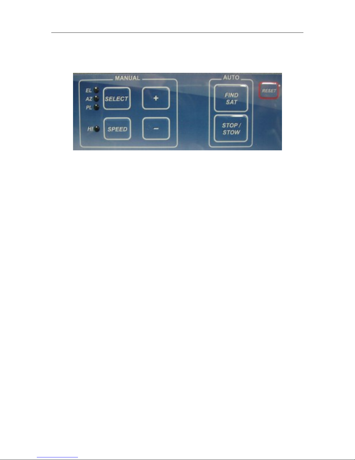
7.2. Manual and Automatic Controls Button Operation
Fig. 12: iNetVu® 7000 Series Controller Front Panel Buttons
How to Find Satellite
Press “FIND SAT” Button.
iNetVu® Mobile Platform will automatically attempt to locate, lock, peak and enable the system
onto the configured satellite or last satellite to lock/enable system. Pressing the FIND SAT button
for 1 second or less will initiate satellite searching routine (on SAT0, default) or last satellite
searched. Holding down the FIND SAT for 3 seconds or more will bring up the satellite menu and
display choice of 5 satellites or 4 Beam Colors to select from. Once in the satellite menu pressing
the FIND SAT will search on the selected Satellite, Beam or Beam Color. The LCD keypad can
also be used to maneuver to the required satellite, use the arrow keys (right or left) to move over
to the required selection and press FIND SAT will launch satellite search routine on that selection.
Search routine will ignore GPS and RF status until after compass heading has been read to
reduce search time. If GPS and RF conditions not met after 60 seconds the search will fail and a
message will be displayed.
How to Stow the Antenna
Press “STOP/STOW” Button, and hold for 2 seconds.
iNetVu® Mobile Platform will automatically re-center itself and lower into the stow position.
How to Stop
Press “STOP/STOW” Button (do not hold). Stops all ongoing operations such as motor
movements and automatic functions, like Find Satellite and Stow.
How to Manually Move the Mobile Platform
Press “SELECT” to select the axis of motion you wish to move. The LED corresponding to the
axes chosen will light up. Press “SPEED H/L” to select the speed (LED ON – HI, LED OFF -
LOW). Press and release “+” and “–“for short duration movement & angle readings. Press and
hold “+” and “–“for long duration movement. Warning: User must watch antenna limit sensors
(EL UP/ST, AZ ST, PL ST) when using manual controls. See LCD ‘Monitor’ section explanation
for more details.
← → ↑
↓
ENTER
EXIT
C-COM Satellite Systems Inc. Page 29 of 164
How to Turn ON/OFF the Controller
Turn off the AC power switch on the back panel of the iNetVu® 7000 Series Controller.
When using DC external power source, the DC input power ON/OFF is controlled by the external
source.
How to Reset the Controller
Press “RESET” Button
Power-cycles the iNetVu® Controller
DOES NOT reset default values
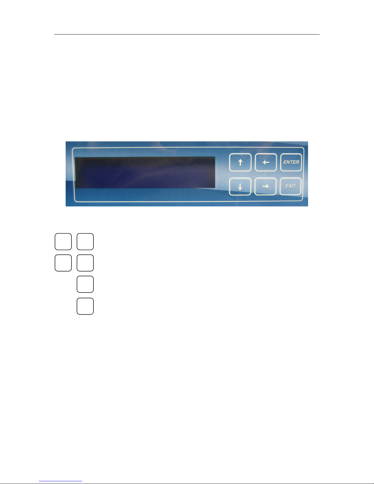
7.3. LCD Screen and Navigator Keypad Operation
Fig. 13: iNetVu® 7000 Series Controller LCD and Keypad Navigator
Used to move the cursor position.
Used to select a displayed function
Used back out of a selection and return the display to the previous selection

MONITOR
OPERATION
CONF2
TEST (TST)
INFO
iNetVu® 7000 Controller LCD Menu
MAIN
EL
AZ
PL
GP
SM
S1
S2
MB
IP
GW
*Common *Tooway *HN_KA
SS0 BLU BM
SS1 ORG ----
SS2 PRP ----
SS3 GRN -----
SS4 SS4 -----
TE TE TE
TD TD TD
AZ AZ AZ
PL PL PL
CM CM CM
CA CA CA
CR CR CR
S2
MB
EL
AZ
PL
GP
C1
C2
C3
SG
IP
SR
E&A&P
DPY
DPYQ
DPY_C
CP
A_ACP
M_ACP
S_ACP
CC1
CC2
DVB_D
DVB_P
MOD
SYS1
ERR
CONF1
S1
SM1
SM2
C-COM Satellite Systems Inc. Page 30 of 164
7.4. Front Panel Menu Navigation Tree
The following is a tree consisting of a list of the menu options available with the LCD
interface.
Fig. 14: iNetVu® 7000 Series Controller LCD Menu Options
*Note: These are not sub-menus and do not exist under the OPERATION menu.
They are merely used to identify the different sub menu options under the
OPERATION menu depending on the modem service that is configured.
Note: In order for the user to make changes to configuration data in a sub-
category of the “CONF1 or CONF2” menu, or apply changes to data in a subcategory of the “TEST” menu, the ‘↑’ button on the keypad must be pressed above
the data portion in the sub-category before changes can be made.
For example, if the user wishes to change the longitudinal value of the target
satellite position in the S1 subcategory of the “CONF1” menu. The steps involved
include:
1) Navigating to the ‘CONF1’ menu on the main screen using the ‘→’ button.
2) Press the “ENTER” button once the cursor is above the ‘CONF1’ menu.
3) At this point, the user should be in the ‘CONF1’ menu after entering password and
can select any of the sub-categories available. Press the “ENTER” button once the
cursor is above the ‘S1’ sub-category.
4) To change the longitudinal coordinate of the target satellite, navigate to the area of
where this information is located, and press the ‘↑’ button once to enable modification.
5) At this point, the user can change the character values of the longitudinal coordinate
by using the ‘↑’ and ‘↓’ buttons. The ‘→’ and the ‘←’ buttons can be used to navigate
between characters.
6) Press the “ENTER” button once complete.

MONITOR
This menu branch allows the user to monitor the status of the iNetVu
Mobile Platform, its components, and displays information
concerning the iNetVu 7000 Series Controller and the Satellite
Modem / VSAT.
OPERATION
This menu branch allows the user to perform miscellaneous
functions, such as enabling/disabling the transmitter, Find Satellite,
Stow, and perform axes calibrations, etc.
CONF1
This menu branch allows the user to configure and save the 5
Satellite parameters with 5 Beacon settings as well as other
configurable options for satellite searching.
CONF2
This menu branch allows the user to configure the iNetVu ® System,
including platform, modem parameters, and controller.
TST
This menu branch allows the user to run demo test on all three axes,
as well as check/test compass, deploy the antenna, and ACP
testing.
INFO
This menu branch allows the user to verify the 7000 Series controller
/ modem settings, such as software versions, hardware versions,
DVB module, and error codes.
iNetVu 7000 Control
BY C-COM
MONITOR OPERATION
CONF1 CONF2 TST INFO
C-COM Satellite Systems Inc. Page 31 of 164
7.5. Opening Screen
When powering the iNetVu® 7000 Series Controller, the LCD will display one of the
following during the initial boot-up sequence.
Fig. 15: LCD Opening Screen
7.6. Main Menu
The iNetVu® controller is ready for usage when the following is displayed on the LCD.
There are Six (6) Main Menu items to select from: MONITOR, OPERATION, CONF1,
CONF2, TST, and INFO.
Fig. 16: LCD Main Menu

MAIN
Displays real-time system status and receive signal.
EL
(Elevation) Displays real-time current drawn and speed settings for the
elevation motor, as well as real-time elevation angle and limits, offset,
window size, and Elevation adjustment gap.
AZ
(Azimuth) Displays real-time current drawn and speed settings for the
azimuth motor, as well as real-time azimuth angle and limits, window
size, and AZ zero.
PL
(Polarization) Displays real-time current drawn and speed settings for
the polarization motor, as well as real-time polarization angle and limits,
window size, and PL zero.
GP
Displays GPS Status and coordinates.
SM
(Search Mode) Displays compass status, Search Mode (RF status).
S1
(Satellite) Displays Target Satellite longitude and the antennas target
coordinates. This branch also contains the DVB Carrier programmed
and the LNB Power
S2
(Satellite) Displays Reference Satellite longitude and the DVB Carrier
programmed for the reference satellite along with the LNB Power
MB
(Modem and Beacon Receiver) Displays Modem status as well as the
Beacon Receiver frequency and signal (if a beacon receiver is used)
IP
Displays IP of iNetVu 7000 Series Ethernet Port, and the VSAT modem
IP.
GW
(Gateway) Displays Subnet, and Gateway IP.
MAIN EL AZ PL GP SM
S1 S2 MB IP GW
C-COM Satellite Systems Inc. Page 32 of 164
7.6.1. MONITOR
This section describes briefly what each item and menu represents. For a more detailed
explanation of each menu, see the configuration section of this manual. (Section 7.6.4)
Fig. 17: Monitor Menu

E-90.0 U D S A -45.7 S VV ST
P-34.6 S 30N M140D 0U
1
3
5 6 4
7
2
8
C-COM Satellite Systems Inc. Page 33 of 164
7.6.1.1. MAIN
This branch menu displays the real-time Elevation, Azimuth, Polarization Angles, their
respective limits (Up, Down, Stow), the RF Receive Signal, Signal Strength, and the
System Status.
Fig. 18: “MAIN” (Main) Display
1 – Elevation Angle and Limit Indicators
740/750/950/980 Mobile Platform Range: -90 to 65+
981/985/755 Drive-away Platform Range: -90 to 93+
1200/1500/1800 Mobile Platform Range: -90 to 76+
Flyaway Antenna (1200Q) 5 to 78+
Airline Checkable (1210A) 9 to 99+
1201 Drive-away -90 to 93+
Elevation Angle will be –90.0 when the Elevation Stow Indicator is ON for mobile/drive-away units
U Elevation up Limit has been reached.
Typically set above 75 for 1200/1500/1800 Mobile Platforms, above 65 for 740/950/980
Mobile Platforms, and above 90 for the 1201/985/755 Drive-away Platforms. The Flyaway
is set above 78.
D Elevation down Limit has been reached.
Typically set between 5 and 10 for 1200/1500/1800 Mobile Platforms and between 0
and 10 for 740/950/980 Mobile Platforms.
S Elevation Stow Limit has been reached.
2 – Azimuth Angle and Stow Limit Indicator
Range: -200 to +200
Flyaway Range: -180 to +180
Airline Checkable: -195 to +195
S Azimuth Stow Limit has been reached.
Mobile Platform should be physically centered on the Azimuth axis.

C-COM Satellite Systems Inc. Page 34 of 164
3 – Polarization Angle and Stow Limit Indicator
740/950/980 Mobile Platform Range: -70 to 70
1500/1800 Mobile/Flyaway Platform Range: -90 to 90
1200 Mobile Platform Range -90 to 90(ST at +65˚)
981/1201 Drive-away Platform Range: -90 to 90 (ST at +/-50˚ for 981)
Ka75/ka98 1800 Circular Band Signals will have the Polarization Angle disabled, and will display
“DDD” Stow Limit will also be disabled and display “STF”.
S Polarization Stow Limit has been reached.
Mobile Platform should be physically centered on the Polarization axis.
The New Gen 981 and 1201 platforms will stow at angle +/-50 (981) and angle +/-90
(1201) based on last PL target angle.
4 – GPS Status Flag and Compass Status Flag
The first letter represents the GPS status, and the second letter represents the Compass status
(i.e. VV, FF, OO, FO, OF, OV, VO).
V GPS/Compass Status is Valid/Normal
F GPS/Compass Status has failed
O GPS/Compass Coordinates have been overridden
5 – System Status (status meanings explained in the software section of this report)
AC Azimuth Calibration
AT ACP Testing
CC Compass Calibration
DT Dish Testing
II Idle
MM Manual Movement
PC Polarization Calibration
PK Peaking (PA/PE)
PS Positioning
SR Searching
ST Stowed
6 – Receive RF/DVB Signal
Receive RF Signal as measured from the LNB. The letter ‘N’ next to the RF Value indicates the
LNB is not being powered properly and there is an issue with the RF connection, whereas no letter
next to the RF value indicates the LNB is powered properly. When the system is not in RF search
Mode, and is searching via DVB carrier, the value represents the DVB signal, and the letter “L” next
to the value indicates a DVB signal LOCK.
7 – Modem Status
Displays the receive strength of the satellite, and the Modem/Transmitter Status.
D Transmitter Disabled
E Transmitter Enabled
U Unknown (Communication with Satellite Modem / VSAT has failed)
(E.g. M140D represents modem signal strength of 140, and transmitter is disabled)

E0.0 D U S I/S: 0-6 U D
S: 5 AD: 3 C:32 O: 31
1
2
3
5 4 6
C-COM Satellite Systems Inc. Page 35 of 164
8 – Beacon Receiver Signal
This section represents the strength of the Beacon Receiver Signal (if used). The letter ‘U’ next to
the Beacon Signal indicates an unlocked status, whereas the letter ‘L’ next to the Beacon Signal
indicates a Locked on satellite status.
7.6.1.2. EL
Displays real-time current drawn and speed settings for the elevation motor, as well as
real-time elevation angle and limits, offset, window size, and Elevation adjustment gap.
Fig. 19: “EL” (Elevation) Display
1 – Real-Time Elevation Angle
E (Elevation) The number value after the “E” represents the real time elevation angle.
D The letter “D” will appear to indicate Down Limit has been reached on the elevation axis
U The letter “U” will appear to indicate UP Limit has been reached on the elevation axis
S The letter S will appear to indicate the Elevation angle has reached the stow position
(Antenna Stowed).
The inclinometer used to read the elevation angle will compensate for an incline up to +/-
15º. For example if a user is on a 10º slope and the system is searching along the
azimuth, if the elevation reading changes due to a horizontal incline, the elevation will
adjust to maintain the correct elevation angle while searching along the azimuth.
2 – Current and Speed Settings
I/S Real-Time current of the elevation motor is to the left of the dash, and speed constant of
the elevation movement is to the right of the dash (i.e. 0-6 represents current of 0 at a set
speed of 6).
U The letter “U” will appear if there is an up movement on the elevation axis.
D The letter “D” will appear if there is a down movement on the elevation axis.
3 - Search Window Elevation Limit
This value represents the amount of degrees the antenna will point above and below the calculated
target elevation coordinate when searching for satellite. (S: 5 – implies elevation search window is
5º)

A0.0 S I/S:0-6 L R
W: 60 Z: 346.1
1
2
3
4
C-COM Satellite Systems Inc. Page 36 of 164
4 – Advanced Search Elevation Gap (El Adjustment)
When parked on an incline, azimuth movement can affect the Elevation angle. This happens
because the azimuth is on a fixed plane parallel to the roof of the vehicle and the Elevation angle is
relative to gravity. For example, at a very high incline, moving 20 degrees of azimuth could
gradually drop (or raise) the elevation 3 degrees from the calculated target. Since this could cause
you to miss the satellite, we stop the azimuth movement, re-position the Elevation to the target,
then continue the azimuth sweep. The default value is 3 degrees of elevation change allowed
before adjustment. Since these adjustments will increase the amount of time it takes to find the
satellite, we recommend to park the vehicle on the most level surface available.
5 - Elevation Offset
The number of degrees at which the iNetVu® Mobile Software will offset the reading from the
Inclinometer in order to produce an accurate (+/- 2°) Elevation Angle (e.g. O: 31 implies elevation
offset of 31). These values initially default, and are set after target calibration is performed.
6 – Elevation of Compass Reading Status
Number of degrees that the Antenna requires to be elevated to ensure that the compass is level
and is able to acquire an accurate compass reading (see Appendix 1 for default values).
7.6.1.3. AZ
Displays real-time current drawn and speed settings for the azimuth motor, as well as
real-time azimuth angle and limits, search window size, and AZ zero.
Fig. 20: “EL” (Elevation) Display
1 – Real-Time Azimuth Angle
A (Azimuth) – Real time Azimuth angle reading, down to the tenth of a decimal.
S The letter “S” will appear to indicate the stow Limit has been reached on the azimuth axis
2 – Current and Speed Settings
I/S Real-Time current of the azimuth motor is to the left of the dash, and speed constant of
the azimuth movement is to the right of the dash (i.e. 0-6 represents current of 0 at a set
speed of 6).
L The letter “L” will appear if there is a ‘left’ movement on the azimuth axis.
R The letter “R” will appear if there is a ‘right’ movement on the azimuth axis.
(See Appendix for detail on default speed and current settings)

P0.0 S I/S:0.0-7 L R
O:0.0 Z: 90
1 2 3
4
C-COM Satellite Systems Inc. Page 37 of 164
3 - Search Window Azimuth Limit
This value represents the amount of degrees the antenna will search for satellite along the azimuth
axis to the left and right of the calculated target antenna azimuth coordinate when searching for
satellite. (I.e. W: 60 implies 60º search to the left and right of the target antenna azimuth angle,
totally 120º)
Note: system may overshoot by 10º from the set window limits and thus the
displayed value will be off 10º on either side of the target angle.
4 – Z (AZ Zero)
AZ Zero is an A/D value from the potentiometer which physically determines where the iNetVu®
Mobile Software places Azimuth Angle 0°. The AZ Zero may vary approximately +/-15% from the
Default values (see Appendix).
AZ Zero is calculated during the Azimuth Calibration process.
7.6.1.4. PL
Displays real-time current drawn and speed settings for the polarization motor, as well
as real-time polarization angle and limits, offset, and PL zero.
Fig. 21: “PL” (Polarization) Display
1 – Real-Time Polarization Angle
P (Polarization) – Indicates the real time polarization angle of the iNetVu® Antenna.
S The letter “S” will appear to indicate the stow Limit has been reached on the polarization
axis
2 – Current and Speed Settings
I/S Real-Time current of the polarization motor is to the left of the dash, and speed constant
of the polarization movement is to the right of the dash (i.e. 0.0-7 represents real-time
current of 0.0 and a set speed of 7).
L The letter “L” will appear if there is a ‘left’ movement on the polarization axis.
R The letter “R” will appear if there is a ‘right’ movement on the polarization axis.
See Appendix 1 for default speed and current values.
3 - Polarization Offset
This value represents the offset in the polarization angle.

GPS: V V0
LA: 45.4N LG: 75.6W
1 1 2
2
3
RF :N-N-55-30N
CP:V-000 AZ_W :60
4
C-COM Satellite Systems Inc. Page 38 of 164
4 – Z (PL Zero)
PL Zero is a converted A/D value from the potentiometer and or a software
generated fixed value from inclinometer that physically determines where the
iNetVu® Mobile Software places Polarization Angle 0°. The PL Zero may vary
approximately +15% from the default values for the potentiometer (see Appendix
1) while the inclinometer will provide a more accurate reading with minimal
variances. The PL Zero is used to convert the A/D calculated value during the
polarization calibration process. Polarization calibration is not valid for platforms
(980 and 1200 version 3.0+) and all platforms equipped with the inclinometer tilt
sensor. PL Zero value is set to 90° ± 2 for all tilt sensor equipped units.
7.6.1.5. GP
Displays GPS Status and current GPS Heading.
Fig. 22: “GP” GPS Display
1 – GPS Status
V V GPS Status is Valid, second V is for Velocity Status
F GPS Status has failed
O GPS Coordinates have been overridden
2 – GPS Coordinates
LA Current Latitude Coordinate rounded to one decimal place in degree format.
LG Current Longitude Coordinate rounded to one decimal place in degree format.
7.6.1.6. SM
Displays Search Modes Status, Compass Status, Compass Heading and AZ Window.
Fig. 23: “SM” Search Mode and Compass Display
(See Compass Configuration section under CONF1----SM1 (CP))

C-COM Satellite Systems Inc. Page 39 of 164
1 – RF Search Mode Status
N RF Mode is disabled; Y will be displayed when enabled.
N RF override mode is disabled; O will be displayed when enabled.
RF Threshold (55) Value will be displayed here, this value is configurable.
RF/DVB signal value (30N) – If in RF search mode this will represent RF signal value, if in DVB
Mode it will display DVB carrier signal. The letter ‘N’ next to the
RF Value indicates the LNB is not being powered properly.
The letter “L” next to the value indicates a DVB signal LOCK.
2 – CP (Compass) Status
V Valid – The compass reading is functioning properly
O Override – the compass has been overridden, and direction entered manually
considered
FS Full Search – searches a full 360º search window.
3 – Compass Heading/ Calibrate/Check Compass Routine
Displays Compass Heading after Compass has been read.
Approximate Headings: North 354
East 87
South 176
West 265
Antenna will rotate 90° to each of the following positions and read the compass
at each: 0°, 90°, 180°, -90°, 0° and display the compass headings. Vehicle front
end (windshield window) must be pointed North during these routines to achieve
proper compass headings and a software pop-up will be displayed on the pc
screen to ensure this Platform is properly orientated.
4 - AZ Search Window Status
The Search Window is the area of the sky which the iNetVu® Mobile System will
search for the desired Satellite. It uses a rectangular window and searches for
the Satellite using smaller concentric windows until the desired Satellite is found.

3 63W E0 A0 P0
3 0990 30000 DB-7 18
1
5
7
3
6
4
8
2
C-COM Satellite Systems Inc. Page 40 of 164
7.6.1.7. S1
This menu displays the Target Satellite Number and Longitude, Target Antenna
Coordinates, DVB Transponder (Frequency, Symbol Rate, and Code Rate) and LNB
Power.
Fig. 24: “S1” (Target Satellite) Display
1 - Target satellite number
2 - Target Satellite Longitude and Hemisphere
3 - Target Satellite Antenna Elevation, Azimuth (within reference to true north), and
Polarization coordinates respectively.
4 - Transponder Number
There are usually six (6) transponders for each satellite stored into the controller
memory, 0 – 2 are horizontal receive, and 3-5 are vertical receive, the user may
overwrite the transponder data with his/her own (see configuration section).
5 - DVB Transponder Frequency (MHz)
6 – Transponder Symbol Rate (Ksps)
7 –Transponder Code Rate.
DB-1 = 1/2
DB-2 = 2/3
DB-3 = 3/4
DB-5 = 5/6
DB-7 = 7/8
AUTO (DVB-S2 ACM SELECTION)
8 – Power Supplied to LNB from the 7000 Series Controller for the Target Satellite

E 63W E0 A0 P0
0 0990 30000 DB-7 DD
1
4
6 2 5
3
7
C-COM Satellite Systems Inc. Page 41 of 164
7.6.1.8. S2
This menu displays the Reference Satellite Status, Longitude, Target Antenna
Coordinates, DVB Transponder (Frequency, Symbol Rate, and Code Rate) and LNB
Power. The reference satellite is another search option that could be utilized by the user.
If this option is disabled, you may disregard all this information.
Fig. 25: “S2” (Reference Satellite) Display
1 – Reference Satellite Longitude, Hemisphere, and Status
Status “D”: implies the reference satellite option is disabled
Status “E”: implies the target satellite option is enabled
2 – Reference Satellite Antenna Elevation, Azimuth, and Polarization coordinates
respectively.
3 - Transponder Number (for reference satellite)
There are six (6) transponders for each satellite stored into the controller
memory) 0 – 2 are horizontal receive, and 3-5 are vertical receive. The user may
overwrite the transponder data.
4 – Reference Satellite DVB Transponder Frequency (MHz)
5 – Reference Satellite Transponder Symbol Rate (Ksps)
6 – Reference Satellite Transponder Code Rate. (DVBS1 requirement)
DB-1 = 1/2
DB-2 = 2/3
DB-3 = 3/4
DB-5 = 5/6
DB-7 = 7/8
7 – Power Supplied to LNB from the 7000 Series Controller for the Reference Satellite

MODEM : INIT
BR :1448.05 0/0dB
1
2
SQ : 15 TC :24 RC :6 A :D
BR :1448.05 0/0dB
3 1 2
5
4
C-COM Satellite Systems Inc. Page 42 of 164
7.6.1.9. MB
This menu displays the modem status, beacon frequency and signal strength.
Fig. 26: Modem and Beacon Receiver
1 – Modem Communication Status
INIT will appear if still initializing communication.
NA will appear if no modem selected.
SQ: with value will appear if modem is communicating with controller.
2 – Beacon Receiver Frequency and Signal Strength
The Beacon Receiver is an optional unit that could be used to acquire satellite with the
7000 Series Controller. See “iNetVu User Manual – Beacon Receiver” (7000 Controller
section) for details
7.6.1.9.1 Hughes Modem Status (Only)
1 – Modem Communication Status.
INIT will appear if still initializing or no communication
NA will appear if no modem selected.
SQ will appear with after modem communication is establish (Modem TX Disabled).
2 – Displays the status of the (TX) satellite receiver transmit state.
3 – Displays the status of the (RX) Satellite receiver receive state.
4 – ACP status enables or disables the ACP routine after locking on signal.
D Disables the ACP after locking on signal

C_IP : 70.232.247.50
M_IP: 70.232.247.49
1
2
S_IP : 255.255.255.0
G_IP: 70.232.247.49
1
2
C-COM Satellite Systems Inc. Page 43 of 164
E enables the ACP after locking on signal in which an isolation value is displayed after successfully
passing the 2 tests.
A_ST ACP has started
A_SP ACP has passed
5 – Beacon Receiver Frequency and Signal Strength
The Beacon Receiver is an optional unit that could be used to acquire satellite with the
7000 Series Controller. See “iNetVu User Manual – Beacon Receiver” (7000 Controller
section) for details
7.6.1.10. IP
This menu displays the IP address of the user configured iNetVu® 7000 Series Controller
and Modem. (Ensure the IP address of the modem configured is the actual IP address of
the modem, and that the 7000 Controller is operating on the same network as the
modem)
Fig. 27: “IP” (Controller and Modem IP) Display
1 – C_IP: iNetVu® 7000 Series Controller’s IP Address – Default 192.168.0.2
2 – M_IP: The Modem IP configured in the 7000 Series Controller.
7.6.1.11. GW
1 – S_IP (iNetVu® 7000 Series Controller’s Subnet Mask IP Address – Default
255.255.255.0)
1. Gateway IP Address (Default: 192.168.0.32 or 192.168.100.1 depends on Modem
Type/Service)

SS0
(Find Satellite 0) Performs automatic satellite acquisition for configured
satellite 0.
(Find Satellite BLU) Performs automatic satellite acquisition on the Blue
Beam.
(Find Satellite BEAM ID) Performs automatic satellite acquisition on the
Beam ID selected.
BLU
BM01
SS1
(Find Satellite 1) Performs automatic satellite acquisition for configured
satellite 1.
(Find Satellite ORG) Performs automatic satellite acquisition on the
Orange Beam.
ORG
SS2
(Find Satellite 2) Performs automatic satellite acquisition for configured
satellite 2.
(Find Satellite PRP) Performs automatic satellite acquisition on the
Purple Beam.
PRP
SS3
(Find Satellite 3) Performs automatic satellite acquisition for configured
satellite 3.
SS0 SS1 SS2 SS3 SS4
TE TD AZ PL CM CA CR
1
3
4 2 5
7
6
BLU ORG PRP GRN SS4
TE TD AZ PL CM CA CR
1
BM01
TE TD AZ PL CM CA CR
1
8
C-COM Satellite Systems Inc. Page 44 of 164
7.6.2. OPERATION
Fig. 28: Default Operation Menu
Note: The OPERATION sub menu items may differ for Ka services. The satellite
numbers (SS0, SS2, etc...) will be replaced with GPS location Beam Colors for
Tooway or Beam ID for HN_KA.
Fig. 29: Operation Menu, Tooway service on left and HN_KA service on right

GRN
(Find Satellite GRN) Performs automatic satellite acquisition on the
Green Beam.
SS4
(Find Satellite 4) Performs automatic satellite acquisition for configured
satellite 4.
TE
(Transmitter Enable) Enables the transmitter after locking onto the
designated satellite.
TD
(Transmitter Disable) Disables the transmitter after locking onto the
designated satellite.
AZ
(Azimuth Calibration) Performs a complete Azimuth Calibration.
PL
(Polarization Calibration) Performs a complete Polarization Calibration.
CM
Allows Manual Compass Calibration at specified angles.
CA
Performs automatic compass calibration.
CR
Restores Compass to factory calibrated defaults.
C-COM Satellite Systems Inc. Page 45 of 164
1 – Find Satellite
Automatically finds and locks onto the satellite signal by communicating with the
Satellite Modem and using the GPS coordinates, the compass heading and
internal parameters of the Satellite Modem. Typically, it takes approximately 3-5
minutes to find satellite. The “Service Type” must be selected and “Update Beam
Table” button applied for the correct Beam ID information to propagate when
using HN_KA Modem Type.
If the Antenna is already pointed on the satellite, clicking Find Satellite will re-
peak or re-deploy the Antenna onto the last satellite signal found. There are 5
configurable satellites in the 7000 Series Controller (S0-S4) and each is now
capable of having 5 configurable beacon settings. Press “Enter” onto the
corresponding satellite, Beam Color or Beam ID to begin search.
Note: The Tooway service will display Beam Colors while the HN_KA and iDirect
Dual Beam Ka service will display Beam ID number.
2–Transmitter Enable (TE)
Enables the Transmitter once locked onto satellite.
3 –Transmitter Disable (TD)
Disables the Transmitter once locked onto satellite.

C-COM Satellite Systems Inc. Page 46 of 164
4 –Azimuth Calibration (AZ)
This feature will only be available on Legacy mounts. All new generation platforms (i.e.
Ka-75V, 98H/98G/98V, 1201 etc...) will have this option disabled by default.
Performs a complete Azimuth Calibration.
Antenna will move CW to a set point.
Antenna will move back in the opposite direction to locate Stow switch.
Antenna will attempt to locate the cut-off edges of the Azimuth Stow Switch and center itself.
After detecting at which angles the ST Switch turns OFF, the Azimuth zero position is
calculated and the AZ Zero(Pot) is set at the zeroed A/D value.
5 – Polarization Calibration (PL)
Performs a complete polarization calibration. On platforms with tilt sensors the
system will complete a PL Zero point calibration and set the Zero point value. Tilt
sensor must be levelled prior to running the Calibrate PL routine on system with
Polarization tilt sensors.
Antenna will completely rotate counter-clockwise to the physical limit and temporarily record
the A/D value from the Potentiometer.
Antenna will completely rotate clockwise to the physical limit and temporarily record the A/D
value from the Potentiometer.
Based on the A/D values of the two (2) physical limits and the maximum range of motion for
the Mobile Platform, the center angle is determined.
Antenna will center itself and attempt to locate the cut-off edges of the Polarization Stow
Switch.
After detecting at which angles the ST Switch turns OFF, the Polarization zero position is
calculated and the PL Zero is set at the zeroed A/D value.
6 – Manual Compass Calibration (CM)
Ensure platform is oriented to point North (see Fig 30. below) this compass
calibration is performed manually. It is intended to calibrate the compass by
moving to three angle positions (0, 90, and 180). The compass is manually
calibrated at each angle and then followed by a compass check to validate the
angle readings. Manual Calibration procedure may require to be performed
multiple times before angle readings are acceptable.
7 – Automatic Compass Calibration (CA)
Ensure that there are no metallic objects that could interfere with the Compass,
and that the Mobile Platform is on level surroundings.
Orient the Mobile Platform as depicted in the following figure. If Platform is
vehicle mounted ensure front end (windshield window) is pointed north. It is

This end faces North
(Front of Vehicle)
This end faces South
North - 354 N
West - 265
South - 176
East - 87 W E
S
This end faces North
(Front of Vehicle)
This end faces South
C-COM Satellite Systems Inc. Page 47 of 164
recommended that you use an external compass to be as accurate as possible
with the orientation.
Note: The New Generation Platforms (these include and not limited to ka-
75V, 98H/98G/98V and 1201A) are equipped with newer versions of the
compasses which are factory calibrated and do not require calibration in
the field unless performed by C-COM support authorization only. Restore
CP replaces the compass calibration on systems equipped with the newer
compass version, these systems are identified by platform version. Please
consult with C-COM Technical support before running the compass
calibration.
Fig. 30: Compass Orientation and Approximate Values
Software will display a pop-up on the pc screen asking end user to verify correct
orientation of platform after Compass Calibration is selected within software.
The Antenna will now rotate in 90 intervals and attempt to calibrate the
compass. The LCD Screen will indicate that the Compass Calibration has been
completed successfully or not.

S1 SM1 SM2
PWD:: ********
RST :: *********
C-COM Satellite Systems Inc. Page 48 of 164
8 – Compass Restore (CR)
Restores the compass to the factory calibrated default state as was shipped from
the manufacturer. Use this button only after consulting with C-COM Support.
7.6.3. CONF1
This Menu will allow the user to configure and save all 5 Satellites with 5 beacon settings
as well as other configurable Search Modes of the iNetVu® System. A description of
each menu and their purpose is outlined below. This section explains the different submenus of the configuration (CONF1) menu, and what each field parameter means.
7.6.3.1. Password Protection
The LCD Configuration Interface is password protected.
Fig. 31: Password screen
The default password is “password” (case sensitive).Use the “↑” or “↓” button to
select the characters, and the “←” or “→” to navigate through the character fields. Press
on the “ENTER” button of the front panel when the password has been completely
entered.
If the password has been changed, and the user does not know the password, entering
a specific reset ID in the bottom row will reset the password to the default (“password”).
The Reset ID (RST) is “123456789”
7.6.3.2. Configuration Menu (CONF1)
Fig. 32: CONF1 (Configuration) Menu

S1
Allows the user to configure and save the Orbital slot / Longitude of the
desired Target Satellite (0-4 satellites), along with the corresponding
DVB Transponder and LNB Power Requirement. 5 satellites can be
configured and saved with different search parameters
SM1
Allows the user to configure and save the search mode (RF Search or
DVB mode), Compass, RF Threshold and AZ search window.
SM2
Allows Modem Beam ID configuration and Beacon configuration for each
Satellite. 5 configurable Beacon settings can be configured to work with
5 satellites. Beam ID for Dual or Multiple Beam search can also be set.
0 093.0W S11/S2A O: 090.0
0 0999 09999 DB-7 18
1
4
5
3
2
C-COM Satellite Systems Inc. Page 49 of 164
7.6.3.3. S1
This menu allows for the configuration of the target satellite(s) (5 satellites maybe
configured and saved) and the satellite polarization offset. If the user is using DVB as a
search option, the transponder information must be entered along with the LNB power
requirements.
Fig. 33: “S1” (Target Satellite) Configuration Display
1 – Target Satellite
Satellite Number and Orbital slot / Longitude of the desired Satellite. The Find
Satellite command will use this value when attempting to find and lock onto a
satellite signal. The user can configure and save up to 5 satellites (0 to 4).
2 – DVB Configuration
The user can configure the type of carrier to search for either DVB-S1 or DVB-
S2ACM. The DVB-S2 ACM carrier requires controller model 7000B Rev 1.0 or
greater.
3 – Satellite Transmit Polarization Offset (range: -180 to +180)
In North America and not limited to the rest of the world
1201/1200/1800/1500/1.2 Flyaway –Horizontal Receive (Offset = 0, with
feed/OMT position standing up),
Vertical Receive (Offset = 90, with feed/OMT position flat). Polarization is based
on the Receive (RX) Polarity.
Vertical RX and Horizontal TX (VH) requires Pol Offset be set to 90.
Horizontal RX and Vertical TX (HV) requires Pol Offset be set to 0.
Therefore: VV requires Offset to be set to 90 and HH to 0.

C-COM Satellite Systems Inc. Page 50 of 164
Eutelsat configuration will automatically propagate the offset value after entering
0 or 90.
980/740 – Offset = 0 (considering OMT is adjusted manually).
4 – DVB Transponder Information.
0 – Transponder Number (0-2 are for Horizontal Receive, 3-5 are for Vertical Receive)
0999 – Transponder Frequency (MHz)
09999 – Transponder Symbol Rate (Ksps)
DB-7 – Transponder Code Rate (DVBS1 requirement)
DB-1 = 1/2
DB-2 = 2/3
DB-3 = 3/4
DB-5 = 5/6
DB-7 = 7/8
5 – LNB Power (Target Satellite)
In cases where the LNB requires more power than the modem can provide, or if
the user would like to power LNB from the controller, or if the user would like to
find satellite without the use of a modem, this option allows for power from the
controller to be supplied to the LNB through the RX IN cable from the controller
to the platform itself.
DD – will disable this option, and provide power to the LNB straight from the
modem. In this case, a splitter must be used for the RF connection as depicted in
the figure below.
Fig. 34: RF Cable Setup for DIS selection
7000 Series Controller Power Output Range Option Capabilities: 13, 14, 18, 19,
V @ 500mA (max). If the user chooses to power the LNB from the controller,
he/she should verify the power/voltage range requirements of the LNB in use,
and configure the iNetVu® 7000 Series Controller according to those
power/voltage requirements.

RF:N-O- 50
CP :N- 000 AZ_W :060
1
2
4
3
C-COM Satellite Systems Inc. Page 51 of 164
7.6.3.4. SM1
This menu allows for the configuration and saving of the Satellite Search Modes with a
total of 5 different configurable satellites, each can be configured with different RF
Search Mode parameters.
Fig. 35: “SM1” Search Mode Configuration Display
1 – RF Search Mode
N RF Mode is disabled; Y will be displayed when enabled.
N RF override mode (second digit) is disabled; O will be displayed when enabled.
RF Threshold (50) Value will be displayed here, this value is configurable.
2 – CP (Compass)
V Valid – The compass reading is functioning properly
N Normal – Full Search NOT selected, (nor is compass overridden).
O Override – the compass has been overridden, and direction entered manually considered
F Full Search – searches a full 360º search window, Fly-away systems (70 º), Full search
also overrides compass.
3 – Compass Heading
Compass Heading after Compass has been read.
Approximate Headings: North 354
East 87
South 176
West 265
Calibrate/Check Compass Routine see CPC under OPERATION or CP under
TST.
4 - AZ Search Window
The Search Window is the area of the sky which the iNetVu® Mobile System will
search for the desired Satellite. It uses a rectangular window and searches for
the Satellite using smaller concentric windows until the desired Satellite is found.
The window value represents the amount of degrees the antenna will search for

MID:0008
B :0952.00/22.0
1
2
C-COM Satellite Systems Inc. Page 52 of 164
satellite along the azimuth axis. Window will be expanded from 60 to 90 degrees
if satellite not found during the first run.
Note: system may overshoot by 10º from the set window size limits.
7.6.3.5. SM2
This Menu allows the user to set the modem Beam ID (dual or multi beam modems) for
the desired Satellite search as well as set the Beacon and ACQ Attenuation with
different values for 5 Configurable Satellites. 5 different Beacon settings can be
configured and saved.
Fig. 36: “SM2” Modem Beam ID and Beacon Configuration Display
1 – Modem Beam ID
Modem Beam ID number can be entered from the front panel. Used with
modems that support dual or multi beam search ( iDirect and HN). Beam
switching will depend on the currently set Beam ID in the modem and the
required ID for existing location, switching occurs and modem reboots if different
beam ID is required from the current one set in the modem. Modem will remain
on the last active Beam ID that locked on signal. The Multi-Sat Search option
must be enabled and the different Sat No. configured with the proper Beam ID for
the beam switching to toggle to the next Beam in the list.
2 – BR (Beacon Receiver Frequency and Power Level – Optional)
If the Optional Beacon Receiver is used to acquire satellite, the user may enter
the beacon frequency of the satellite that he/she wishes to lock onto, also the
Power level for peaking on the Beacon Signal. See “iNetVu User Manual –
Beacon Receiver” (7000 Series Controller section) for details
7.6.4. CONF2
This menu will allow the user to select and set the configuration of the iNetVu® System
as well as the Reference satellite option. The target satellite(s) S1 is configured in the
CONF1 menu. A description of each menu and their purpose is outlined below. This
section explains the different options of the configuration menu, and what each
component means. A step-by-step procedure of how to configure the system is
explained in the corresponding Service Provider Based Quick Start User Manuals.
Please refer to the manual based on the service you are using with the 7000 Series
Controller.

S2
(Reference Satellite Option Use Only) Allows the user to configure the
Orbital slot / Longitude of a reference satellite, along with the
corresponding DVB Transponder and LNB Power Requirement.
MB
Allows the user to configure the Modem parameters such as transmit
and receive polarization, as well as frequency and symbol rate (if
required). New Beacon Reference search added.
EL
(Elevation) Allows configuration of the elevation current, limits, slow
speed, window size, and adjustment gap.
AZ
(Azimuth) Allows configuration of the azimuth zero, stow limit, speed,
search window size, and current limits.
PL
(Polarization) Allows configuration of the polarization zero, skew
adjustment, stow limit, polarization offset, speed, and current limits.
GP
(GPS and Compass) Configuration of GPS coordinates and Compass
parameters.
C1
Contains Multi-Sat Search option, controller configuration feature
information such, Motion Protection, ES/NO, Inclined Orbit etc...
C2
Contains configuration of the platform type, serial number, and the
controller console port.
C3
Contains the password information. The user may change the password
in this screen.
SG
(Gateway and Subnet) Allows for the configuration of the controller
subnet IP address, as well as the controller gateway IP address.
IP
Configuration screen of the controller IP address, and the VSAT
modem’s IP address.
SR
The user may configure the service type, as well as the interface used to
establish communication between the controller and modem (telnet,
console, etc.) Ka services (HN_KA) will have the ability to change Beam
ID.
S2 MB EL AZ PL GP
C1 C2 C3 SG IP SR
C-COM Satellite Systems Inc. Page 53 of 164
7.6.4.1. Configuration Menu (CONF2)
Password must be entered before accessing CONF2 menu and submenu.
Fig. 37: CONFIG2 (Configuration) Menu

E 093.0W S11/S2A O: +90
0 0999 09999 DB-7 18
1
4
5
3
2
C-COM Satellite Systems Inc. Page 54 of 164
7.6.4.2. S2
This menu allows for the configuration of the reference satellite parameters. If the user is
using the Reference Satellite Search option, the transponder information must be
entered along with the LNB power requirements of the reference satellite used. The
controller will lock onto the Reference satellite DVB carrier, and will pivot to the target
satellite position to peak on the modem signal. Users acquiring Satellite signal using RF
Search or direct DVB search with the Target satellite DO NOT require this option, and
should ensure that this method is disabled (as will be explained below) . Reference
Satellite Search option will only work with DVB search method. The Max ES/NO is
automatically disabled and reverted back to default value of 255 when Ref Sat is
enabled.
Fig. 38: “S2” (Reference Satellite) Configuration Display
1 – Reference Satellite
Orbital slot / Longitude of the Reference Satellite. If the reference satellite option
is enabled, the Find Satellite command will use this value when attempting to
find and lock onto the reference satellite signal then pivot to the target satellite
position. Only works with DVB search mode.
“D” – The user should select “D” if he/she does not wish to use this option.
“E” – If the user wishes to use the reference satellite, “E” should be selected.
2- DVB Configuration
The user can configure the type of carrier to search for either DVB-S1 or DVB-
S2A. The DVB-S2 ACM carrier requires controller model 7000B Rev 1.0+ or
greater. DVBS2 carriers are recommended.
3 – Satellite Transmit Polarization Offset (range: -180 to +180)
In North America and not limited to the rest of the world
981/1201/1200/1800/1500/1.2 Flyaway – Horizontal Receive (Offset = 0) with
feed/OMT standing up.
Vertical Receive (Offset = 90) with feed/OMT position flat.
980/740 – Offset = 0 (considering OMT is adjusted manually)
Only RX Polarity is referenced for the Pol Offset field allowing both Cross-Pol and
Co-Pol to work with setting the Pol Offset to 90 or 0 depending on the Receive
Polarity required. Rx = V = 90 (feed/OMT position flat) and Rx = H = 0
(feed/OMT position standing up) for Cross-Pol and Co-Pol.

C-COM Satellite Systems Inc. Page 55 of 164
4 – DVB Transponder Information for the reference satellite.
0 – Transponder Number (0-2 are for Horizontal Receive and 3-5 are for Vertical Receive)
0999 – Transponder Frequency (MHz)
09999 – Transponder Symbol Rate (Ksps)
DB-7 – Transponder Code Rate (DVBS1 requirement)
DB-1 = 1/2
DB-2 = 2/3
DB-3 = 3/4
DB-5 = 5/6
DB-7 = 7/8
5 – LNB Power (Reference Satellite)
In cases where the LNB requires more power than the modem can provide, or if
the user would like to power LNB from the controller, or if the user would like to
find satellite without the use of a modem, this option allows for power from the
controller to be supplied to the LNB through the RX IN cable from the controller
to the platform itself.
DD – will disable this option, and provide power to the LNB straight from the
modem. In this case, a splitter must be used for the RF connection as depicted in
the figure below.
Fig. 39: RF Cable Setup for DIS selection
7000 Series Controller Power Output Range Option Capabilities: 13, 14, 18, 19,
V @ 500mA (max)
If the user chooses to power the LNB from the controller, he/she should verify the
power/voltage range requirements of the LNB in use, and configure the iNetVu®
7000 Series controller according to those power/voltage requirements.

0990.0 30000000 HV W/E
Y N BRR :1210.99/22.0
1
4
2
3
5
6
7
C-COM Satellite Systems Inc. Page 56 of 164
7.6.4.3. MB
Fig. 40: “S2” (Reference Satellite) Configuration Display
1 – Configured Satellite Modem Receive Frequency in MHz with no decimals. (HNS
Only)
2 – Configured Satellite Modem Symbol Rate in sps. (HNS Only)
1Msps = 1000 Ksps = 1 000 000 sps
3 – Receive and Transmit Polarization.
HH – Horizontal Receive, Horizontal Transmit
HV – Horizontal Receive, Vertical Transmit
VH – Vertical Receive, Horizontal Transmit
VV – Vertical Receive, Vertical Transmit
Receive polarity is represented by the first character, while Transmit polarity is
represented by the second character
4 – Hemisphere of location of modem.
This is typically used for the HNS modem; other service providers may not need
this requirement.
E – East
W – West
Modems operating in the eastern hemisphere require E to be selected, while
modems operating in the western hemisphere require W to be selected.
5 – Auto Transmit Disable
N: If “N” is selected, the controller will leave the modem status as is if a reset is pushed to the
modem from the NOC or for any other reasons after communication between controller and modem
is re-established.
Y: If “Y” is selected, the controller will automatically disable the modem transmit if a reset occurs
once communication is re-established between the controller and the modem.
6 – ACP Enable / Disable
N: If “N” is selected, ACP will be enabled and the controller will try to perform ACP for HNS
integrated modems after peaking on satellite and before enabling the transmitter.

O: 31 A: 03 L: EEE
W: 05 C:32 S: 6 I:07.0
2
1
5
6
3
4
7
C-COM Satellite Systems Inc. Page 57 of 164
Y: If “Y” is selected, ACP will be disabled and the controller will not perform ACP for HNS
integrated modems after peaking on satellite, and will try to enable transmitter.
7 – Beacon Reference Search
This new feature allows operator to use the Beacon as a reference for satellite search.
7.6.4.4. EL
The EL menu allows for the Configuration of the elevation axis. Options include
configuring the elevation offset, the satellite search window, the elevation adjustment
gap, the mechanical elevation limits, the slow speed, and the current limits.
Fig. 41: “EL” (Elevation Configuration) Display
1 – Elevation Offset
The Elevation Offset is specific to each type of platform. See Appendix 1 for a list
of all the elevation offset default values. It is the number of degrees at which the
iNetVu® Mobile Software will offset the reading from the Inclinometer in order to
produce an accurate (+/- 2°) Elevation Angle. The user may set the offset with
the range of 15º-55º, although altering this number from its default value may
give an inaccurate offset reading. This should not be tampered with without first
consulting a C-COM Technical Support Representative.
2 –Speed Setting
S The user may configure the slow speed of the elevation movement. The slow speed is a
basis for the satellite searching procedure.
3 - Advanced Search Elevation Gap (EL Adjustment)
With a configurable range of (2º-20º) this parameter is used to determine the
small incremental adjustments required for a more accurate satellite search.
Decreasing this value will add accuracy to the Search Window, but will increase
the search time. This value is used while searching on an inclined surface. For
instance A: 03 means the elevation angle will adjust if 3º gap from the calculated
angle. This value is set by default for optimum performance.

C-COM Satellite Systems Inc. Page 58 of 164
4 – Limit Switches (L: EEE)
Allows the enabling and disabling of the UP, DOWN, and STOW limits
respectively.
The first character (EEE) represents the UP limit. The second character (EEE)
represents the DOWN limit and the third character (EEE) represents the STOW
limit. The user my change the limit configuration between:
D - Disable Limit
This option disables UP, DN, and ST limits for testing and troubleshooting (i.e. DEE – represents
disabled up limit, and enabled down and stow limit).
E – Enable Limit
Once enabled, the up, down and stow limits will be activated whenever the up, down, and stow
sensors have been triggered on the iNetVu® Mobile platform.
5 – Elevation Search Window
The Search Window is the area of the sky which the iNetVu® Mobile System will
search for the desired Satellite. It uses a rectangular window and searches for
the Satellite using smaller concentric windows until the desired Satellite is found.
The Search Window range is pre-set by default for optimum performance;
however this offset may be manually changed in the range of 2º-20º.
The default Elevation (Vertical) range is 3° on each side of the Target Point.
Increasing the size of the Search Window will increase the ability to find the
desired Satellite, although increasing the Search Window will lengthen the
search time. The search window will expand from 3 to 5 if first search run fails to
lock on satellite.
6 – Current Settings
A software controlled current protection for the Mobile Platform’s elevation
motors. When any of the Mobile Platform’s motors are moving at the associated
speed, the current drawn to move the motor is monitored and should it exceed
the Current Limit, an error message will appear. For Motor Speeds that are not
listed (Speed 1, 2, 4, 5, 7, 8), the Current Limit for those speeds is calculated
using a percentage of the Current Limit above it. See Appendix 1 for the default
current limits for all iNetVu® Mobile Platforms.
• Current Limit 8 – 90% of Current Limit 9
Fig. 42: Elevation Coverage of search window

Z: 346.9 CP_O:+00 E
S: 6 I: 07.0
1 4 5
3
2
C-COM Satellite Systems Inc. Page 59 of 164
• Current Limit 7 – 80% of Current Limit 9
• Current Limit 5 – 90% of Current Limit 6
• Current Limit 4 – 80% of Current Limit 6
• Current Limit 2 – 90% of Current Limit 3
• Current Limit 1 – 80% of Current Limit 3
I - Configurable Current Limit for Slow Speed (6) which is displayed by the S: field (#2 speed
setting) movement is set to 7.0.
(i.e. I:07.0 and S: 6 Represents Current Limit of 7 A @ speed 6.
7 – Elevation of Compass Reading
Number of degrees that the Antenna requires to be elevated to ensure that the
compass is level and is able to acquire an accurate compass reading for finding
satellite (see Appendix 1 for default values).
7.6.4.5. AZ
The AZ menu allows configuration of the Azimuth axis, including AZ zero and stow limit,
azimuth search window size, slow speed movements, and current limits at high and slow
speeds.
Fig. 43: “AZ” (Azimuth) Display
1 – Configurable AZ Zero (Pot)
AZ Zero is an A/D value from the potentiometer calculated upon azimuth
calibration which physically determines where the iNetVu® Mobile Software
places Azimuth Angle 0°. The AZ Zero may vary approximately +15% from the
Default values (see Appendix 1). The user may edit these values through this
window; however any changes may result in failure to recognize the correct 0°
angle. This parameter has a configurable range of (150-700).
2 – Compass Offset
A fixed offset could be used to adjust the compass heading. This value would be
added to the calculated compass heading to compensate for any consistent
inaccuracy of the compass reading.

C-COM Satellite Systems Inc. Page 60 of 164
3 - Stow Limit
Enabling this function allows for the iNetVu® system to trigger the stow limit when
the mechanical stow range of the azimuth is reached. Disabling this limit, may
result in failure to initiate the automatic stow command.
E – Enable Stow Limit
D – Disable Stow Limit
4 –Speed Setting
S The user may configure the slow speed of the azimuth movement. The
slow speed is a basis for the satellite searching procedure.
5 – Current Settings
A software controlled current protection for the Mobile Platform’s azimuth motors.
When any of the Mobile Platform’s motors are moving at the associated speed,
the current drawn to move the motor is monitored and should it exceed the
Current Limit, an error message will appear. For Motor Speeds that are not listed
(Speed 1, 2, 4, 5, 7, 8), the Current Limit for those speeds is calculated using a
percentage of the Current Limit above it. See Appendix 1 for the default current
limits for all iNetVu® Mobile Platforms.
• Current Limit 8 – 90% of Current Limit 9
• Current Limit 7 – 80% of Current Limit 9
• Current Limit 5 – 90% of Current Limit 6
• Current Limit 4 – 80% of Current Limit 6
• Current Limit 2 – 90% of Current Limit 3
• Current Limit 1 – 80% of Current Limit 3
I - Configurable Current Limit for Slow Speed (6) movement is displayed under the I: while
the speed under S:
(i.e. I: 07.0 Represents Current Limit of 7 A @ speed 6)

Z: 090.0 DE
O: +0 S: 6 I: 1.5
1 3 5
2
4
C-COM Satellite Systems Inc. Page 61 of 164
7.6.4.6. PL
The PL menu allows for the configuration of the polarization axis. Options include the
setting of the PL zero, as well as the skew adjustment and stow limit functionality, the
polarization offset, slow speed, and current limits for fast and slow speeds.
Fig. 44: “PL (Polarization ) Configuration
1 – PL Zero
PL Zero is used to convert the A/D value from the potentiometer that physically
determines where the iNetVu® Mobile Software places Polarization Angle 0. The
potentiometer PL Zero may vary approximately +15% from the default values
(see Appendix 1). The PL Zero is calculated during the Polarization Calibration
process. All New Generation platforms (981, 1201, 1200 Fly-Away and 1210 AC)
and some legacy units are equipped with Tilt Sensors. PL Zero point calibration
calculates and sets the Zero value for all platforms. The user may edit these
values through this window, however any changes may result in failure to
recognize the correct 0° angle. This parameter has a configurable range of (50-
500).
2 – Skew Adjustment and Stow Limit Function
Allows the enabling and disabling of the skew adjustment and polarization stow
limit respectively.
The first character (EE) represents the skew adjustment. The second character
(EE) represents the Polarization ST limit. The user my change the limit
configuration between:
EE – Enable Skew Adjustment, Enable Polarization Stow limit
DE – Disable Skew Adjustment, Enable Polarization Stow limit
ED – Enable Skew Adjustment, Disable Polarization Stow limit
DD – Disable Skew Adjustment, Disable Polarization Stow limit
For an iNetVu® 1200/1500/1800 Ku Mobile Platforms, the Polarization Stow Limit
is constantly ON. The Skew Adjustment will rotate the antenna on the azimuth
axis 90° on each side of the peaked signal and then re-position on signal with an
adjustment to the polarization for any inclined surface.
For 2 axial (movement on El and AZ) Ka Mobile Platforms DD the Skew and the
Polarization Stow limit will always be disabled.

G :O 45.41N 75.62W
1
2
3
C-COM Satellite Systems Inc. Page 62 of 164
3 - Polarization Offset
By default this polarization-offset value is set to +0°. If there happens to be a
requirement for a polarization offset in the satellite position, the user may
manually enter this value in this area. This area is also updated automatically if
the skew adjustment procedure recognizes inaccuracy in the target polarization
angle. Misconfiguring this field will result in undesirable results.
4 –Speed Setting
S The user may configure the slow speed of the polarization movement. The slow speed is a
basis for the satellite searching procedure. See Appendix 1 for details.
5 – Current Settings
A software controlled current protection for the Mobile Platform’s polarization
motors. When any of the Mobile Platform’s motors are moving at the associated
speed, the current drawn to move the motor is monitored and should it exceed
the Current Limit, an error message will appear. For Motor Speeds that are not
listed (Speed 1, 2, 4, 5, 7, 8), the Current Limit for those speeds is calculated
using a percentage of the Current Limit above it. See Appendix 1 for the default
current limits for all iNetVu® Mobile Platforms.
• Current Limit 8 – 90% of Current Limit 9
• Current Limit 7 – 80% of Current Limit 9
• Current Limit 5 – 90% of Current Limit 6
• Current Limit 4 – 80% of Current Limit 6
• Current Limit 2 – 90% of Current Limit 3
• Current Limit 1 – 80% of Current Limit 3
I - Configurable Current Limit for Slow Speed (6) movement is displayed under the I:
while the speed under S:
(i.e. I: 1.5 Represents Current Limit of 1.5 A @ speed 6)
7.6.4.7. GP
Allows for the Configuration of the GPS parameters and settings,
Fig. 45: “GP (GPS ) Configuration

Indicates a situation or practice that might result in
property or equipment damage.
B :D E S: 130 MS : E DH : D
UN : D IN : D MP : E BP : L
1
4 6 5
3
7
2
8
C-COM Satellite Systems Inc. Page 63 of 164
1 – GPS Status Configuration
N Use Coordinates from GPS Antenna
O Override GPS and use the coordinates entered (2) and (3). Enables the GPS coordinates
to be manually overridden. This should only be enabled in the event that the GPS Antenna
is malfunctioning and the user has a reliable, alternate source for coordinates.
Note 1: If you have overridden the GPS coordinates, they will have to be updated if the
Mobile Platform has moved to a new location since the overridden values will no longer be
accurate.
Note 2: Overriding the GPS will affect movement protection on all mobile platforms
preventing them from automatically stowing if vehicle movement and/or severe motion are
detected. If the vehicle drives off with the platform deployed, it will not stow as it should
because the GPS is overridden. Moving vehicle GPS speed and location must reach min
5km/h and or Elevation angle changes by 2 or more degrees in order for the movement
protection feature to trigger.
2 – GPS Latitude Coordinate
3 – GPS Longitude Coordinate
7.6.4.8. C1
This menu allows for the configuration of the controller input settings as well as the
platform type.
Fig. 46: “C1” Controller Display Screen 1
1 – B (iDirect TX Broadcast)
The 7000 Series Controllers can be configured to broadcast with iDirect service.
This allows iDirect users with broadcast configured modems, to lock onto a DVB
carrier, and enable the transmitter in the iDirect modem automatically after
peaking through the 7000 Series Controller.
D – Disabled
E – Enabled

C-COM Satellite Systems Inc. Page 64 of 164
2 – ES
The Maximum energy to noise of a modem or SNR signal that can be configured to save
time during the satellite peaking routine. If Maximum ES/NO value reached the system
will stop the peaking routine otherwise routine continues with the complete peaking
process. Modifying this parameter may inhibit satellite searching sequence and stop the
peaking before the highest possible receiving signal is reached. Only change this value if
the highest Maximum ES/NO value is known otherwise leave at default value of 255 to
achieve highest MAX ES/NO signal. This option will be disabled when Ref Sat is
enabled.
3 – Multiple Satellite Search
The multiple satellite search when enabled will search on the selected satellite when the
“FIND SAT” (SAT0/1/2), command is triggered, if the search fails to lock on the first
selected satellite, the search continues on the next and eventually onto the last; if the
search fails on all three satellites a failed status will be displayed. All 3 satellite settings
will default to the first configured satellite in the list, each satellite has to be manually set
in the order that the operator prefers the search to begin on.
D – Disabled
E – Enabled
4 - Unattended Operation
This option is used for remote operations where system is left unattended as the
name indicates, mainly for unmanned sites. This feature must not be used when the
iNetVu system is being moved around or in transport mode. In this case, the system
should be powered off completely. Otherwise, there is a risk of the antenna attempting to
deploy while vehicle is moving. Please ensure this feature is turned off when vehicle is in
transit from one location to another.
The user may disable, or set the unattended re-deploy delay time to 5, 10, or 15
minutes. If the system detects motion it will wait 1min, if dish still on signal the system
will re-acquire satellite, otherwise the dish will stow due to motion or movement, the
system will automatically re-acquire satellite depending on the user entered delay time
after stow. Initial stow will only wait 30 seconds no matter what the selected delay time is
set to before re-acquiring satellite.
For example, if the user selects 5 minutes from the drop down menu, and the system
stows due to motion or movement while operational, on first stow it will only wait 30
seconds before re-acquiring satellite.
The second stow, system waits Five (5) minutes + 30 seconds before
automatically re-acquire the satellite signal. The routine uses the following formula:
Waiting Time for re-acquire == 30S+ (retry times*selected delay time) default retry time
at first stow is 0, second stow is 1, etc… until one (1) hour (3600 seconds) reached. If
after (1) hour system does not find satellite it will continue to try on every hour thereafter.
The retry time will be reset 0 after each time the system locks on satellite.
DIS: Disabled
1: Re-acquire Satellite in 5 minutes
2: Re- acquire Satellite in 10 minutes

C-COM Satellite Systems Inc. Page 65 of 164
3: Re- acquire Satellite in 15 minutes
DANGER: The system may try to deploy if this option is selected and vehicle
becomes in motion. Unattended option must be disabled when vehicle is moving
and system is NOT powered off.
5 – Inclined Orbit (Sat_Inc)
Enabling this option will allow the system to maintain signal with an inclined
orbital satellite. The user may select the time difference between each re-peak
on the inclined orbital satellite without disabling the transmitter and maximizing
on the signal strength. If signal strength drops before the re-peaking time is due,
the system will automatically re-peak to maintain signal strength. Feature
enhanced and will be used with regular Ka services to maintain strong signal
when platform shifts. This option will not work properly if Motion Protection is
enabled at the same time, disable Motion Protection when inclined option is
enabled.
DIS: Disabled
1: Re-peak every 10 minutes
2: Re-peak every 30 minutes
3: Re-peak every 1 hours
4: Re-peak every 2 hours
5: Re-peak every 3 hours
6: Re-peak every 4 hours
7: Re-peak every 6 hours
8: Re-peak every 8 hours
9: Re-peak every 12 hours
6 – Motion Protection
iNetVu
®
Platform will automatically stow if the antenna detects extreme motion,
such as severe shaking caused by poor weather conditions. If the shaking/shift is
in small increments the system will not stow assuming signal is not lost. If the
small motion/movement count (12 small movements in 30 seconds) logged in a
specific time window exceeds the set threshold the system will re-peak if signal
exists or stow if signal lost. System will redeploy if stowed due to environment
condition and “unattended Operation” is enabled, system will try to redeploy
according to configured unattended time.
D - Disabled
E - Enabled
7 – DHCP Status
The 7000 Series Controllers can be programmed to obtain an IP address from a
DHCP Server (i.e. modem, router, etc.)
D – DHCP Disabled (IP must be entered statically)
E – DHCP Enabled (Controller will dynamically obtain an IP address from the DHCP Server)

C :MDM--9600 TO :+0.0
A98A—2.X--3103
1
3 2 4
5
C-COM Satellite Systems Inc. Page 66 of 164
8 – Beep
This option allows for enabling and disabling the Beeping sound when navigating the LCD screen
through the front panel keypad.
D – Beep Disabled, the sound will be completely removed.
L – Beep Enabled, a beeping sound will occur every 2 seconds.
M – Beep Enabled, a beeping sound will occur every 1 seconds.
H – Beep Enabled, a beeping sound will occur every 500 milliseconds.
7.6.4.9. C2
Fig. 47: Controller Configuration (Screen 2)
1 – Console Port Configuration
Used for the configuration of the console port of the 7000 Series Controllers. The
Console port could be used for the following:
1) MDM (Modem Communication)
If the COM port is used to establish communication between the
Controller and the VSAT Modem (i.e. iDirect, Viasat, etc.), then MDM
must be selected in this field, along with the Baud Rate the Modem
operates on, prior to configuring the Service, and Communication
Interface.
MDM--4800
MDM--9600
MDM--38400
2) B_R (Beacon Receiver)
The Beacon Receiver is a satellite acquisition lock controller that could be
used alongside the 7000 Series Controller as an option. The Beacon
Receiver will lock on the Beacon Frequency of a satellite based on the
power density of the signal. If the optional Beacon Receiver is used, B_R
must be selected for the console. The default baud rate is 2400.

C-COM Satellite Systems Inc. Page 67 of 164
3) DBUG-19200 (internal use only)
4) GLOS (GLONASS GPS)
This option allows for external GLONASS GPS communication between
the Controller and the external GPS device via COM Port. The default
baud rate is 9600.
5) PC
If COM port communication is desired between the 7000 Series Controller
and the IMS software application. The default baud rate is 9600, and
COM1 through COM9 can be selected.
6) GPS
This option allows the user to communicate and output GPS
readings/values from the 7000 series Controller via COM Port (RS232)
connection. The default baud rate is 9600.
2- Platform Type
The user is capable of configuring the platform type using iNetVu LCD panel, as
well as entering the serial number of the platform located next to the connector
plate or on the elevation arm on the platform itself (only the last four or five digits
need be entered). Location of serial number will differ between Legacy and New
Generation platforms. Note the displayed names on the LCD will differ slightly
from the names displayed in the software application.
A75A - iNetVu® A750 Mobile Platform (Ku – Band)
N755A - iNetVu® 75cm New Gen Drive-away Platform (Ka - Band Circular)
A98A - iNetVu® .98cm Mobile Platform (Ku – Band)
N981A - iNetVu® .98cm New Gen Drive-away Platform (Ku – Band)
N985A - iNetVu® .98cm New Gen Drive-away Platform (2 Axis Ka – Band Circular)
Ka-98G (Skyware Global Feed boom)
Ka-98H (HNS Feed boom)
Ka-98V (Viasat Feed boom)
N985B - iNetVu® .98cm New Gen Drive-away Platform (3 Axis Ka – Band Circular)
Ka-98G (Skyware Global Feed boom)
Ka-98H (Spaceway Transceiver)
N987A - iNetVu® .98cm New Gen Drive-away Platform with SMC reflector ((2 Axis Ka – Band Circular)
A12B - iNetVu® 1.2m Mobile Platform (Ku – Band)
A12P - iNetVu® 1.2m Flyaway Platform (Ku – Band)
A12Q - iNetVu® 1.2m Flyaway Platform (Ku – Band)
N121A - iNetVu
Q12A - iNetVu
A15A - iNetVu® 1.5m Mobile Platform (Ku – Band)
A15B/E - iNetVu
A15C - iNetVu® 1.5m Mobile Platform (C – Band Circular)
A18A - iNetVu® 1.8m Mobile Platform (Ku – Band)
A18C - iNetVu® 1.8m Mobile Platform (C – Band Circular)
A18B/E - iNetVu® 1.8m Mobile Platform (C – Band Standard Linear/INSAT)
P18A - iNetVu® 1.8m Flyaway (KU - Band)
P18B/E - iNetVu® 1.8m Flyaway (C – Band Standard Linear/INSAT)
P18C - iNetVu® 1.8m Flyaway (C – Band Circular)
M18A - iNetVu® 1.8m Fixed Motorized (Ku – Band)
M18B/E - iNetVu® 1.8m Fixed Motorized (C – Band Standard Linear/INSAT)
®
1.2m New Gen Drive-away Platform (Ku – Band)
®
1.2m Airline Checkable Platform (Ku – Band)
®
1.5m Mobile Platform (C – Band Standard Linear/INSAT)

C-COM Satellite Systems Inc. Page 68 of 164
M18C - iNetVu® 1.8m Fixed Motorized (C – Band circular)
M18D - iNetVu® 1.8m Fixed Motorized (X – Band circular)
M12A - iNetVu® 1.2m Fixed Motorized (Ku – Band)
M121A - iNetVu® 1.2m Fixed Motorized C-COM version (Ku – Band)
M125A - iNetVu® 1.2m Fixed Motorized C-COM version (Ka – Band)
N18A - iNetVu® 1.8m Drive-away Platform (Ku– Band)
N18B/E - iNetVu® 1.8m Drive-away (C – Band Standard Linear/INSAT)
N18C - iNetVu® 1.8m Drive-away (C – Band Circular)
3 - TO (Mechanical Offset in Polarization Assembly)
This field allows the user to place a fixed offset for the target polarization angle.
This value could make up for any noticeable mechanical offsets in the
polarization assembly of the iNetVu platform between -5º to +5º.
e.g. 1) Calculated Target Polarization Angle = 10º
TX_O = +3º
The iNetVu system will position @ 7º when pointing
e.g. 2) Calculated Target Polarization Angle = 10º
TX_O = -3º
The iNetVu system will position @ 13º when pointing
4 - Platform Serial Number
The user must enter the last four or five-digits of the platform serial number
located next to the connector plate on the iNetVu® Mobile Platform. If platform
and controller were purchased as a set, the number has been preconfigured for
you.
Fig. 48: iNetVu® Platform Identification Tag
5 – Platform Version Number
The user must select the platform version type to ensure the correct configuration
parameters and settings are referenced when operating the system. The platform
version when selected will differentiate the sensor and other hardware configuration on
New Generation platforms which may affect the operation.

PWD :: password
LO :0—10.75 D 9999
1 2 3
4
C-COM Satellite Systems Inc. Page 69 of 164
7.6.4.10. C3
Fig. 49: Controller C3 Configuration
1- Current LCD and Web Interface Password
The user may change this password by using the “↓” and “↑” buttons on the front panel
of the 7000 Series controller and the “→” and “←” buttons to navigate through the
character fields. This password must be remembered in order for the user to re-enter
the LCD screen configuration interface, or the web interface.
2- LO – (LNB)
Configurable to allow satellite accusation when frequency changes, values range from
10.75, 9.75, 10.00, 10.60 and 11.30.
The default value should be set to 10.75, the user is not required to change this value
unless necessary, otherwise select the carrier from the table or enter one if not listed.
3- 22 KHz Tone (Enable/Disable)
This feature allows users to enable/disable the 22 KHz tone for supporting LNB’s.
E – Enabled
D – Disabled
4- DISABLE STOW
The system can be configured to disable the STOW by changing the ID.
8755 – Disables the STOW
8955 – Enables the STOW

S_IP : 255.255.255.0
G_IP: 192.168.0.1
1
2
C_IP : 192.168.0.3
M_IP: 192.168.0.1
1
2
C-COM Satellite Systems Inc. Page 70 of 164
7.6.4.11. SG
This menu will allow the user to configure the subnet mask IP address and the Gateway
IP address of the iNetVu® 7000 Series Controller.
Fig. 50: “GW” (Gateway) Configuration
1 – S_IP (iNetVu® 7000 Series Controller’s Subnet Mask IP Address – Default is
(255.255.255.0)
2 – Gateway IP Address (Default: 192.168.0.1) this can be
changed to support the network you are on.
7.6.4.12. IP
This menu will allow the user to configure the controller IP address, as well as the
Modem IP address.
Fig. 51: “IP” Configuration
1 – iNetVu® 7000 Series Controller’s IP Address
2 – Modem IP Address

ID_TL - 0
PWD :
1
4
2
3
C-COM Satellite Systems Inc. Page 71 of 164
7.6.4.13. SR
This menu will allow the user to configure the controller to the service used (select
modem type) for 2-way satellite communication.
Fig. 52: “SR” (Service) Configuration
1 – Two-Way Mobile Service Selection
Before communication is established with the modem, the user must define the
service in use. The iNetVu® 7000 Series Controller supports several services,
including:
ID – iDirect Service
IS – iPSTAR Service
VA – ViaSat Service
VA – TW – Viasat Tooway Ka Service
V_SBS2 – Viasat SurfBeam2
CT – Comtech Service
RD – Radyne Service
SF – Surfbeam Service
GL – Gilat Service
TY – Tachyon Service
ST – STM Service
PD – Paradise Service
HN – Hughes Service
HN_95 – Hughes Services HN9500 Modem
HN_KA – Hughes Ka Service
ET – Romantis/Eastar Service
AV – EMS/Advent
NT – Newtec
NA - Stand Alone service - Used to locate and lock onto a manually configured satellite using the
DVB receiver unit inside of the controller independent of the modem. The manual configuration
requires:
Orbital Slot of Satellite
Receive Polarization
DVB Type
L-Band or Ku-Band Rx Frequency (kHz)
Symbol Rate (ksps)
FEC Code Rate
2 – Modem Communication Interface
TL - Telnet Interface
CM - Console Port Interface
TP – TCP Interface

E&A&P
Will allow for Demo Testing on all axes (elevation, azimuth, and
polarization) for a user specified angle range.
DPY
Deploys the antenna to a user specified azimuth, elevation, and
polarization position.
DPY_C
Will read the compass heading at a user specified elevation, azimuth,
and polarization target point.
DPYQ
Deploys the antenna to a user specified azimuth, elevation, and
polarization position without moving EL to 30˚ first, and without the extra
steps that exist in DPY.
CP
Tests the compass’ heading and accuracy by rotating the antenna at
90° intervals and comparing the compass readings with the actual
antenna’s movement.
A_ACP
Performs an automatic ACP test for Hughes service.
E&A&P DPY DPYQ DPY_C
CP A_ACP M_ACP S_ACP
C-COM Satellite Systems Inc. Page 72 of 164
HT - HTTP Interface
SN – SNMP Interface
UD – UDP Interface
NA - No modem interface applicable, this option is generally selected with the stand-alone service.
Locking and peaking onto satellite is based on the DVB Signal and not on the modem SNR value.
3 – Modem Delay Time
This allows users to delay Controller communication to allow slower modems to
catch up. The default setting is 0 – 1s user has option for a 10s delay.
4 – Modem Password/CD-KEY
If necessary, the user must enter the modem password into this area for
communication to be properly established. The default password is “P@55w0rd!”
which is based on most iDirect modem requirements. If no password is required,
this area should be left blank.
CD – Key must be entered instead of the password if iPSTAR Service is
selected.
7.6.5. TST
Fig. 53: Test Menu

M_ACP
Performs a manual ACP test for Hughes service.
S_ACP
This operation will stop the ACP test from continuing.
E +20:70:7 P-60: 60:7
A-180: 180:7 DD: D TST
1
2
3
4
5
C-COM Satellite Systems Inc. Page 73 of 164
7.6.5.1. E&A&P
Fig. 54: Test/Demo EL,AZ, PL Configuration
1 – Elevation Range
Allows the user to set the start and stop angle of the elevation axis, as well as set
the specific speed for elevation movement. (E +20:70:7 –implies from angle 20 to
70 at speed 7)
2 – Polarization Range
Allows the user to set the start and stop angle of the polarization axis, as well as
set the specific speed for polarization movement. (P -60:60:7 –implies from angle
-60 to 60 at speed 7)
3 – Azimuth Range
Allows the user to set the start and stop angle of the azimuth axis, as well as set
the specific speed for azimuth movement. (A -180:180:7 –implies from angle 180 to 180 at speed 7)
4 – Axis Selection and looping option
The first two characters refer to the axis selection (i.e. DD: D).
DD Disable Test for all axes
EL Perform test on the Elevation axis only
AZ Perform test on the Azimuth axis only
PL Perform test on the Polarization axis only
AA Perform tests on all the axes.
The third character refers to the looping intervals between tests (i.e. DD: D).
D Disables looping, test will only be performed once.
1 Infinitely loops with 3-seconds interval between tests.
2 Infinitely loops with 6-seconds interval between tests.
3 Infinitely loops with 9-seconds interval between tests.
4 Infinitely loops with 12-seconds interval between tests.

E: +20 P+60
A +180 DPLY
1 2 3
4
C-COM Satellite Systems Inc. Page 74 of 164
5 Infinitely loops with 15-seconds interval between tests.
6 Infinitely loops with 18-seconds interval between tests.
7 Infinitely loops with 21-seconds interval between tests.
8 Infinitely loops with 24-seconds interval between tests.
9 Infinitely loops with 27-seconds interval between tests.
5 – Test Selection
Initiates the test on the specified axes according to the specified ranges, and
speeds.
7.6.5.2. DPY
Deploy antenna to the specified angles.
Fig. 55: Deploy Configuration
1 – Elevation Movement
User-defined elevation angle of deploy.
2 – Polarization Movement
User-defined polarization angle of deploy.
3 – Azimuth Movement
User-defined azimuth angle of deploy.
4 – Deploy
Automatically moves antenna to the manually entered Elevation, Azimuth and
Polarization angles.

E: +20 P+60
A +180 CP_T
1 2 3
4
E: +20 P+60
A +180 DPLY
2 1 3
4
C-COM Satellite Systems Inc. Page 75 of 164
7.6.5.3. DPYQ
DPYQ deploys to the set angles excluding the fine tuning and pre-condition movement
of EL to 30˚ as a first step.
Note: See DPY for parameter functions and meanings as they are identical.
Fig. 56: Quick Deploy Configuration
7.6.5.4. DPY_C
This is the compass test feature. A compass check is performed at the set angles.
1 – Elevation Movement
User-defined target elevation angle offset for compass reading.
2 – Polarization Movement
User-defined target polarization angle for compass reading.
3 – Azimuth Movement
User-defined target azimuth angle for compass reading.
4 – Check Compass at specified target point.
Tests the compass’ heading and accuracy at the user defined Elevation,
Polarization, and Azimuth angles, by rotating the antenna at 90 intervals and
comparing the compass readings with the actual antenna’s movement. This
function is mainly used for testing purposes. Ensure proper orientation (front of
vehicle is point north). Popup (see below) displayed in Software application.

1
2
3
RF :N-N-55-30N
CP:V-0 AZ_W :60
4
C-COM Satellite Systems Inc. Page 76 of 164
Antenna will move to the target Elevation, Polarization, and Azimuth for reading
the compass heading such that the user can determine if the compass reading is
accurate at that point.
7.6.5.5. CP
1 – RF Search Mode Status (values displayed but not used for CP tests/calibrations)
N RF Mode is disabled; Y will be displayed when enabled.
N RF override mode is disabled; O will be displayed when enabled.
RF Threshold (55) Value will be displayed here, this value is configurable.
RF/DVB signal value (30N) – If in RF search mode this will represent RF signal value, if in DVB
Mode it will display DVB carrier signal. The letter ‘N’ next to the
RF Value indicates the LNB is not being powered properly.
The letter “L” next to the value indicates a DVB signal LOCK.
2 – Compass Status
V – Valid
O – Override
F - Failed
3 – Compass Heading
Compass Heading after Compass has been read.
Approximate Headings: North 354
East 87
South 176
West 265
Compass Accuracy Readings
Tests the compass’ heading and accuracy by rotating the antenna at 90
intervals and comparing the compass readings with the actual antenna’s
movement.

CC1
CC2
Contains information pertaining to the iNetVu ® 7000 Controller hardware
version, Controller ID, firmware version, boot loader version, Signal
Threshold, MAC address and configuration ID.
DVB_D
Contains information pertaining to the type of DVB Module in use.
DVB_P
Contains information pertaining to the DVB lock status, as well as the
real-time DVB data such as type, modulation, frequency, code rate, and
symbol rate.
CC1 CC2 DVB_D DVB_P
MOD SYS1 ERR
C-COM Satellite Systems Inc. Page 77 of 164
i. Antenna will center itself; move to the proper Elevation for reading the compass, then read
the compass heading.
ii. Antenna will rotate 90 to each of the following positions and read the compass at each: 0,
90, 180, -90, and 0.
iii. iNetVu® Mobile Software will compare the compass heading values read at each position,
and determine if they differ by approximately 90.
iv. The Compass Check will display a message regarding the accuracy of the compass with a
“PASS” or “FAIL”.
4 - AZ Search Window Status (value displayed but not used)
The Search Window is the area of the sky which the iNetVu® Mobile System will
search for the desired Satellite. It uses a rectangular window and searches for
the Satellite using smaller concentric windows until the desired Satellite is found.
7.6.5.6. A_ACP
Initiates an automatic cross-pol test.
7.6.5.7. M_ACP
Initiates a Manual cross-pol test.
7.6.5.8. S_ACP
Stops the cross-pol testing instantly.
7.6.6. INFO
Displays information regarding the iNetVu® 7000 Series Controller’s firmware and
software versions installed, the Mobile Platform it is configured to, and also any Error
Codes detected.
Fig. 57: “INFO” (Information) Display

MOD
Contains information pertaining to the modem ID, serial number, and
version.
SYS1
Contains information pertaining to the Platform Type, Serial Number.
ERR
Contains information pertaining to the error code if an error occurs.
ID: 2014 SQ_T: 31 H:0
FBV: 7.5.8.0—7.6.1.0
1
3 4
MA:00-40-05-56-3F-C8
CONF_ID:75
1
2
2
C-COM Satellite Systems Inc. Page 78 of 164
7.6.6.1. CC1
This branch menu displays the controller ID (serial number), Hardware Version,
Firmware, and Boot loader Version
Fig. 58: “CC1” (Controller Info 1) Display
1 – Controller ID Number
The iNetVu® Controller Serial Number is located on the base of the controller.
The ID displays the last 4 or 5 digits of the Serial Number.
2 – Signal Quality Threshold
Minimum SNR Value required for the iNetVu® 7000 Series Controller to validate
signal.
3 – 7000 Series Controller Board Hardware Type Version
4 – 7000 Series Controller Firmware and Boot loader version
The firmware version is to the left of the dash (i.e. 7.5.8.0 - 7.6.1.0), and the boot loader version is
to the right of the dash (i.e. 7.5.8.0 - 7.6.1.0).
7.6.6.2. CC2
This branch menu displays the controller MAC address and Configuration ID.
Fig. 59: “CC2” (Controller Info) Display

DVB-S2 (EA) – 0X3C
1
SN: 3863 S: 2 A:D
V: 6.0.9.0
1
2 3 4
C-COM Satellite Systems Inc. Page 79 of 164
1 – iNetVu® 7000 Series Controller MAC address
2 – iNetVu® 7000 Series Controller Configuration ID (for internal use).
7.6.6.3. DVB_D
This branch menu displays the controller DVB Module Type and ID.
Fig. 60: “DVB” (DVB Module) Display
1 – The DVB Module (Tuner) and ID currently embedded into the iNetVu® 7000 Series
Controller.
7.6.6.4. DVB_P
This menu displays the real time DVB module information. If there is no lock on DVB, it
will simply indicate “No Lock”, otherwise it will display real time DVB information such as
DVB type, modulation, code rate (if applicable), symbol rate, and frequency.
7.6.6.5. MOD
This branch menu displays the VSAT Modems ID, Serial Number, and software version
number if proper controller/modem communication is established.
Fig. 61: “MOD” (Modem) Display
1 – VSAT Modem Serial number
2 – Modem Status
1 - Modem Initializing Status
2 - Modem Normal Status
16 - ACP in progress
3 – Satellite Modem’s Model and Firmware Version

Error INFO
1
A12B--1234
R:15754
1
2
C-COM Satellite Systems Inc. Page 80 of 164
4 – Auto ACP Status (Hughes modems only)
7.6.6.6. SYS1
1 – Indicates platform type and serial number.
2 – Data recording information(C-COM internal use)
7.6.6.7. ERR
This branch menu displays the error code if an error occurs. The top line represents the
latest error; the bottom line will represent any previous errors.
Fig. 62: “ERR” (ERROR) Display
1 – iNetVu® Error code display

C-COM Satellite Systems Inc. Page 81 of 164
8. iNetVu® 7000 Series Software
The iNetVu® Mobile Software plays an integral role in connecting you and iNetVu®
Mobile System. The new addition of the iNetVu Setup Wizard will guide first time users
and users that are already familiar with the software application to configure the system
upon first launch. This new feature allows the user to configure the system upon
launching the application with guided information and tips. The iNetVu software has the
ability to communicate with the satellite modem and iNetVu controller automatically
finding and locking onto a satellite; stowing the antenna when use of system is
completed. The user has the option to search for satellite using the following methods,
DVB search; RF search and Beacon receiver with the highest precision. Existing
features such as the ability to configure and save 5 satellites with 5 different Beacon
settings. The user can also monitor real-time system parameters such as Signal
Strength, GPS Coordinates, motor currents, as well as allowing the user the capability of
manually moving the antenna and performing any maintenance tests and calibration
tasks. The user has a choice of languages, currently English, Simplified Chinese &
Traditional Chinese, Russian, Spanish and newly added Swedish to select from on the
fly. Application windows can be resized on your screen or run in full screen mode given
the user the optimized viewing.
8.1. Setup Wizard
The Setup Wizard has been implemented to aid first time users in configuring their
system after the software has been installed. A Pop-up window will show at first launch
allowing the user to use the Setup Wizard (select Yes) or to bypass it (select No) and
use it at a later time. Selecting “Cancel” will exit the Setup Wizard. This window will show
every time the iNetVuMobile7000 software is executed, select “Do not show this
message again” to allow software to go straight to the Controls Window when the
software is launched. The Wizard can be launched at any time as it will be added as a
menu option. See appendix for complete instructional steps on using the Setup Wizard.

Improper use of iNetVu Controls menu can render
the iNetVu® Mobile System inoperable and may be
in violation of FCC regulations. The user can halt
any operation at any time by clicking STOP button
located in the Automatic Controls or on the
Controller front panel.
C-COM Satellite Systems Inc. Page 82 of 164
The Wizard will check Firmware and Software versions if “Yes” is selected to validate the
versions are the same and prompt the user to update the Firmware if they are different.
The wizard will automatically resume after the Firmware update has completed, follow
onscreen prompts. The wizard will not continue and go back to the previous window if
“No” is selected.
8.2. Navigating Menus
To navigate the iNetVu® Mobile Software, right-click the iNetVu® swirl icon located in
the System Tray.
There are 7 options available:
Controls
Maintenance
Configuration
About
Setup Wizard
Language
Exit
8.2.1. iNetVu Controls
The Controls menu allows users to monitor system parameters and manually move the
antenna, as well as conduct automatic processes and functions.

C-COM Satellite Systems Inc. Page 83 of 164
Fig. 63: Controls Window
Signal Strength
A real-time Signal Quality Factor (SQF). A value obtained from the Satellite Modem
when locked onto a signal. Using a red/yellow/green color-coated system, it denotes the
strength of the received signal from the current satellite.
Should the Signal Strength be lower than 29 when locked on satellite, click Find
Satellite again to re-acquire the signal.
Fig. 64: Signal Strength Display

Select Satellite Find Satellite Stow Antenna Stop Operation
C-COM Satellite Systems Inc. Page 84 of 164
Isolation Value
Denotes isolation to the current satellite transponder. This value is not an indication of
signal strength when transmitting a signal.
The Isolation Value will correspond to the transmit quality of an HNS system. Otherwise,
this field is not applicable.
Fig. 65: Isolation Value Display
Date/Time
Current date and time as received from the GPS Antenna. Should the GPS experience
any problems, the alternate source is your PC internal date and time.
Fig. 66: Date/Time Display
Automatic Control
Select Satellite
Choice of 5 Satellites that user can select from by simply clicking on the drop
down arrow. Satellites 0 to 4 can be preconfigured and saved to allow user to
search for desired satellite. Sat 0 is default satellite and will be the one searched
on if no other is selected from the drop down list. Selected Beams will be
displayed in the drop down list for some services.
Find Satellite
Automatically finds and locks onto the satellite signal by communicating with the
Satellite Modem and using the GPS coordinates, the compass heading, and
internal parameters of the Satellite Modem. Typically, it takes approximately 3-5
minutes to find satellite. If the Antenna is already pointed on the satellite, clicking
Find Satellite will re-peak the Antenna onto the signal.
Search routine will ignore GPS and RF status until after compass heading has
been read to reduce search time. If GPS and RF conditions not met after 60
seconds the search will fail and a message will be displayed.
Stow Antenna
Re-centers the antenna and lowers it into the stowed position.
Note: The stow command for the Fly-Away(s) moves the Platform to a home
Fig. 67: Automatic Control Buttons

Elevation UP Limit Indicator
Elevation DOWN Limit Indicator
Elevation STOW Limit Indicator
Azimuth STOW (Left/Right) Limit
Indicator
Polarization STOW Limit Indicator
Elevation Angle
Azimuth Angle
Polarization Angle
C-COM Satellite Systems Inc. Page 85 of 164
position.
Stop Operation
Halts all motor movements and disrupts all communication between iNetVu®
Mobile System components.
Orbital Slot Location of Configured Satellites
The target and Reference satellites section displays the satellite longitude for each
configured satellite. If no satellites are configured, the default is SAT0. The Beam and or
Carrier will be displayed after the SAT 4 field.
Angle and Limit Switch Indicators
Displays real-time angles and Limit Switch status
Fig. 68: Angle and Limit Switch Indicators

C-COM Satellite Systems Inc. Page 86 of 164
When the Elevation STOW Limit Indicator is ON, the Elevation Angle will change
to “–90”, to denote that the iNetVu® Mobile Platform is now stowed. It will remain
“-90” until the indicator turns OFF.
For iNetVu® 1200/1500/1800 KU Mobile Platforms, the Polarization Stow
Indicator will ALWAYS be ON.
981 and 1201 Ku systems will stow the Polarizer on the same side that the PL
target angle was last positioned at. 981 will stow at ±50 degrees from the center.
1201 will stow at ±90 from the center.
The ACFLY-1200 (Airline Checkable) will display L for AZ Left limit, R for AZ
Right limit and ST for AZ Stow.
The 981 and 1201 KU Drive-away Platforms will display “AW” at the +/-180˚ ±5
degree limits.
A YELLOW colour “STF” will appear if a Limit Switch has been disabled in the
Maintenance Menu (Ka-75V, Ka-98H, Ka-98G and Ka-98V Ka platforms).
LHCP or RHCP will display in the PL Angle field for 3rd axis polarization to
indicate right hand or left polarizer position (Ka-98G third axis).
If the Polarization is disabled (for circular signal frequency bands such as Ka-
Band or X-Band) the Polarization Stow Switch must be closed and may display
“DDD”.
Manual Movement
Elevation Up / Elevation Down
Azimuth Left/ Azimuth Right
Polarization Counter-Clockwise / Polarization Clockwise
Using the Duration and Speed parameters, the Manual Movement Buttons allow you to
move the antenna in six (6) directions. For the correct point of reference for the
directional movements, you must be facing the Mobile Platform’s Reflector.

Face Reflector this
direction for correct
Azimuth and Polarization
Orientation
C-COM Satellite Systems Inc. Page 87 of 164
Fig. 69: Orientation Reference for Azimuth and Polarization
Enable/Disable Transmitter
Automatically Enables or Disables the Transmission process. Background will
turn grey when transmitter is disabled and green when the transmitter is
enabled.
Enable/Disable ACP
Enables or Disables the ACP (Automatic Cross-Pol Testing), and Manual
Cross-Pol Testing.
Fig. 70: ACP Option Selection
To Enable ACP, select “AUTO” or “MANUAL” from the ACP drop down list and
click on the ‘Enable/Disable ACP’ Button to initiate.
To Stop ACP testing, select “STOP” from the ACP drop down list, and click on
the Enable/Disable ACP Button to initiate.
Deploy Antenna
Automatically moves antenna to the manually entered Elevation, Azimuth and
Polarization angles.

C-COM Satellite Systems Inc. Page 88 of 164
Fig. 71: Deploy Antenna Input Values
Quick Deploy
Automatically moves antenna to the manually entered Elevation, Azimuth
and Polarization angles without first moving to 30˚ on Elevation. This process
moves to the set angles without the extra angle tuning that occurs with the
Deploy Antenna button.
Duration
Length of time of Manual Movement using increments of 30ms
Speed
Motor Speed of Manual Movement
3 = Slowest, 9 = Highest
Fig. 72: Duration and Speed Input for Manual Movements
DVB Signal (0-255)
DVB Signal received from the DVB Tuner. A “U” next to the value indicates an
“unlocked” status. An “L” next to the DVB value indicates locked signal.
Beacon Signal (0-100)
If the optional beacon receiver is used, the Beacon Signal will
appear in this area along with the power density received from
the satellite. This will only appear when a lock status occurs
which is indicated by an “L” next to the beacon signal value.
RF Signal (30-120)
Displays the real time RF Signal throughout the acquisition
process. A value of 30 that is flashing Red and or Yellow
indicates the LNB is not being powered sufficiently, or there is
an issue with the coax cable connection. Some Ka services will
display 70 if threshold is overridden (i.e. Tooway &
SurfBeam2).
RF Threshold (30-75)
Used in RF mode search for determining proper satellite frequency. This can be

Target Elevation Angle
Target Antenna Azimuth Angle
Target Real Azimuth Angle
Target Polarization Angle
C-COM Satellite Systems Inc. Page 89 of 164
configured and viewed on the Configuration screen.
Antenna Latitude/Longitude
GPS Coordinates acquired from the GPS Antenna or manually overridden values.
EL Motor Current
Current drawn for Elevation Motor (in Milliamps mA)
AZ Motor Current
Current drawn for Azimuth Motor (in Milliamps mA)
PL Motor Current
Current drawn for Polarization Motor (in Milliamps mA)
Target Satellite parameters
Fig. 73: Satellite Target Angles
Target Elevation (Target EL)
Calculated Elevation Angle that the Antenna must point in order to locate the desired
Satellite.
Target Real Azimuth (Target AZ)
Calculated Azimuth Angle that the Antenna must point in order to locate the desired
Satellite in reference to True North.
Target Antenna Azimuth (System Ref. AZ)
Calculated Azimuth Angle that the Antenna must point in order to locate the desired
Satellite in reference to the Mobile Platform’s center position.

This end faces South
This end is the reference for Vehicle
Orientation, this end faces North
This end faces South
North - 354 N
West - 265
South - 176
East - 87 W E
S
This end faces North
(Front of Vehicle)
C-COM Satellite Systems Inc. Page 90 of 164
Target Polarization (Target PL)
Calculated Polarization Angle that the Antenna must be in order to find the desired
Satellite.
Compass Heading
Orientation of the Mobile Platform.
This value is only read during the Find Satellite, Check Compass, and Calibrate
Compass processes.
Fig. 74: Compass Orientation and Approximate Values

System Status Satellite Modem Status GPS Status
Controller Status Motor Status Antenna Sensor Status
C-COM Satellite Systems Inc. Page 91 of 164
Message Panel
Displays real-time status updates, system messages, and error codes.
Fig. 75: Message Panel
Status Panel
The Status Panel describes system operations that are either imminent, taking place, or
the current status of that component. The Status Panel is located at the bottom of the
Basic Controls and Advanced Controls menus, and has a set of four and six message
blocks, respectively.
Fig. 76: Advanced Controls - Status Panel
The indicators notify the user of any actions taking place with a combination of colorcoded messages.
Solid “GREEN” messages indicate a stable and normal condition for that
component.
Flashing or solid “LIGHT BLUE” messages indicate a change in status occurring
that the user should be aware of.
Flashing “RED” and “YELLOW” messages indicates a problem with that
component.
Should the entire Status Panel flash “RED” and or “YELLOW”, a communication failure
between the PC and the iNetVu® Controller has occurred. Ensure that the Controller is
powered, and that all USB drivers and cables (USB, LAN or Serial) are installed
properly.
System Status
Displays current system environment
System Idle
No operations are currently being performed.
ACP Testing
ACP Testing is being performed.

C-COM Satellite Systems Inc. Page 92 of 164
Skew Adjusting
Polarization adjustment to adjust the polarization axis for any vehicle inclination.
The Azimuth Axis will rotate 90º on both sides of the peaked azimuth angle, then
return to the satellite position, and adjust the polarization axes to compensate for
any recognized mount inclination.
Manual Operation
Manually controlled movement via Controls menu has been detected.
Mount Testing
System test or demo being performed via System Test and Demo menu.
Peaking on Satellite
System makes minor adjustments in positioning in order to receive optimal Signal
Strength.
AZ Calibration
Azimuth Calibration is being performed.
PL Calibration
Polarization Calibration is being performed.
CP Calibration
Compass Calibration is being performed.
Positioning
An automatic movement command has been initiated (i.e. Find Satellite or
Deploy Antenna) and the antenna is moving into the designated position.
Searching Satellite
Antenna is performing a search pattern to locate the satellite.
Stowing Antenna
Antenna is being stowed.
Unknown Status
Satellite Modem Communication Status
Indicates the Transmitter status and displays any issues in communication with the
Satellite Modem
Modem TX Enabled
Indicates that the transmitter has been enabled.
Modem TX Disabled
Indicates that the transmitter has not been enabled.
No Modem Communication
The controller is trying to establish communication with the modem and or
No power is applied to the modem.
GPS Status
Displays condition of the GPS signal
GPS Normal
GPS signal is being received from the GPS Antenna.
GPS Failed
GPS signal is not being received from the GPS Antenna.
GPS Override
GPS coordinates have been manually overridden from the Maintenance menu.

C-COM Satellite Systems Inc. Page 93 of 164
Controller Status
Displays communication status between the PC and the iNetVu® Controller
Controller Normal
Indicates normal communication status between the Controller and the PC
Controller Failed
A failure in communication between the Controller and the PC has been
detected.
Motor Status
Displays the movement of the 3-axis motors: Elevation, Azimuth, and Polarization
EL Moving UP / DN
Elevation Motor is moving in the respective direction
(UP = Up, DN = Down)
AZ Moving Left / Right
Azimuth Motor is moving in the respective direction
PL Moving CCW / CW
Polarization Motor is moving in the respective direction
(CCW = Counter Clock-Wise, CW = Clock-Wise)
Motor Unknown
Motor Status cannot be detected.
Antenna Status
Displays any relevant information regarding the Limit Switches, Potentiometers and/or
Inclinometers.
Antenna Normal
Limit Switches are ON/OFF in the correct relation to the Elevation, Azimuth and
Polarization Angles.
Sensor Error
This status is an indication of problem with cabling or hardware and/or controller
setup. Stop and troubleshoot before proceeding.
Antenna Unknown
Mobile Platform cannot be found. Ensure that the iNetVu® Controller is
functioning and that all cables are connected should this indicator appear.

C-COM Satellite Systems Inc. Page 94 of 164
8.2.2. Maintenance
The Maintenance menu has been re-organized to allow the configurable parameters to
exist together on the same window. The Maintenance allows users to configure the
communication between the controller and platform type, as well as various system
parameters for optimal performance. Separate tabs have been added to isolate the 3
axis as well as GPS and Compass for easier configuration.
The Maintenance menu allows users to conduct maintenance tests/processes, override
parameters, and troubleshoot.
Note: It is recommended to power cycle the controller after firmware upgrades or
configuration changes have been saved. Recycling Controller power will confirm
and validate settings to ensure correct values are propagated and displayed on all
screens, this is important especially for Ka platforms.
Click SAVE ALL when any modifications are made, and before power recycling the
controller to ensure data will be saved on controller side.
Fig. 77: iNetVu® 7000 Maintenance Window

C-COM Satellite Systems Inc. Page 95 of 164
8.2.2.1. Platform Parameters
Fig. 78: Maintenance Platform Parameters
Type
The user is capable of configuring the platform in use.
A0750A - iNetVu® A750A (.75m) Mobile Platform (Ku Band)
A0755A - iNetVu® A0755A - New Gen Drive-Away (Ka Band circular)
A0980A - iNetVu® A980A (.98m) Mobile Platform (Ku Band)
A0981A - iNetVu® A981A (.98m) New Gen Drive-Away Platform (Ku Band)
A0985A - iNetVu® .98m New Gen Drive-Away (2 Axis Ka Band circular)
Ka-98G (Skyware Global Feed boom)
Ka-98H (HNS Feed boom)
Ka-98V (Viasat Feed boom)
A0985B - iNetVu® .98m New Gen Drive-Away (3 Axis Ka Band circular)
Ka-98G (Skyware Global Feed boom)
Ka-98H (Spaceway Transceiver)
A0987A - iNetVu® .98m New Gen Drive-Away w/SMC Reflector (2 Axis Ka Band)
A1200B/C - iNetVu® A1200B/C (1.2m) Mobile Platform (Ku Band)
A1200P - iNetVu® A1200P (1.2m) Flyaway Platform (Ku Band)
A1200Q - iNetVu® A1200Q (1.2m) Flyaway Platform (Ku Band)
A1201A - iNetVu® A1201A (1.2m) New Gen Drive-Away Platform (Ku Band)
A1210A - iNetVu
A0120A - iNetVu
A0121A - iNetVu
A0125A - iNetVu
A1500A - iNetVu® A1500A Mobile Platform (Ku Band)
A1500B/E - iNetVu® A1500B Mobile Platform (Standard C Band Linear/INSAT)
A1500C - iNetVu® A1500C Mobile Platform (C Band Circular)
A1800A - iNetVu® A1800A Mobile Platform (Ku Band)
A1800B/E - iNetVu® A1800B Mobile Platform (C Band Standard Linear/INSAT)
A1800C - iNetVu® A1800C Mobile Platform (C Band Circular)
A0180A - iNetVu® A0180A - 1.8 Fixed Motorized (Ku Band)
A0180B/E - iNetVu® A0180B/E - 1.8 Fixed Motorized (Standard C Linear/INSAT)
A0180C - iNetVu
A0180D - iNetVu
A1801A - iNetVu
A1801B/E - iNetVu
A1801C - iNetVu
A1810A - iNetVu
A1810B/E - iNetVu
A1810C - iNetVu
®
A1210A Airline Checkable Carbon Fibre Reflector (Ku Band)
®
A0120A – 1.2 Fixed Motorized (Ku Band)
®
A0121A – 1.2 New Gen Fixed Motorized (Ku Band)
®
A0125A – 1.2 New Gen Fixed Motorized (Ka Band)
®
A0180C - 1.8 Fixed Motorized (C Band Circular)
®
A0180D - 1.8 Fixed Motorized (X Band Circular)
®
A1801A - 1.8 Drive-Away (Ku Band)
®
A1801B - 1.8 Drive-Away (C Band Standard Linear/INSAT)
®
A1801C - 1.8 Drive-Away (C Band Circular)
®
A1810A - 1.8 Flyaway (Ku Band)
®
A1810B/E - 1.8 Flyaway (C Band Standard Linear/INSAT)
®
A1810C - 1.8 Flyaway (C Band Circular)

C-COM Satellite Systems Inc. Page 96 of 164
Platform Serial Number
The user will be required to enter the last four or five-digits of the platform serial
number located next to the connector plate on the iNetVu® Mobile Platform.
Fig. 79: Platform Identification
Platform Hardware Version
This field identifies hardware changes in the New Generation platform types.
PL (Skew) Offset for OMT
This field allows the user to place a fixed offset for the target polarization angle.
This value could make up for any noticeable mechanical offsets in the
polarization assembly of the iNetVu platform between -5º to +5º.
e.g. 1) Calculated Target Polarization Angle = 10º
TX_O = +3º
The iNetVu system will position @ 7º when pointing
e.g. 2) Calculated Target Polarization Angle = 10º
TX_O = -3º
The iNetVu system will position @ 13º when pointing
8.2.2.2. GPS and Compass
Fig. 80: Maintenance – GPS Parameters

C-COM Satellite Systems Inc. Page 97 of 164
GPS Override Checkbox
Enables the GPS coordinates to be manually overridden. This should only be enabled in
the event that the GPS Antenna is malfunctioning and the user has a reliable, alternate
source for coordinates. If this box is checked, the GPS coordinates should be manually
entered in the ‘GPS Latitude’, and the ‘GPS Longitude’ fields described.
**Note: If you have overridden the GPS coordinates, they will have to be updated if
the Mobile Platform has moved to a new location since the overridden values will
no longer be accurate.
Warning: Overriding the GPS prevents the movement protection feature from
working properly, and will not stow the antenna if vehicle drives off, as neither
speed nor GPS relocation can be detected. Moving vehicle speed must reach min
5km/h plus Elevation angle change of 2 degrees or more with GPS coordinates
change in order for the movement protection feature to trigger.
GPS Latitude
This field represents the Latitudinal GPS coordinates of the iNetVu® system.
GPS Longitude
This field represents the Longitudinal GPS coordinates of the iNetVu® system.
Fig. 81: Maintenance – Compass Parameters
Compass Reading Elevation Angle
Number of degrees that the Antenna requires to be elevated to ensure that the compass
is level and is able to acquire an accurate compass reading.

C-COM Satellite Systems Inc. Page 98 of 164
Disable Auto Calibrate Compass Offset
If this option is unchecked the following will take place. Auto Calibration on compass
occurs when the angle difference of 20 degrees or more is detected between AZ angle
and System AZ Ref when the system finishes the satellite search routine and locks on
signal. A compass offset value is than automatically entered and is used the next time a
Find Satellite command is triggered. When this option is checked, it will NOT Auto
Calibrate the compass offset.
Tips and Recommendations
Compass Issues?
If you are in an area where there is magnetic interference or the compass readings are
incorrect, it is recommended to run “Calibrate Compass or Restore CP” function.
The routines may require to be run multiple times to achieve acceptable angle readings.
Contact C-COM SUPPORT for more information.
Manual Compass Calibration
Performs a three point calibration. This is a manual calibration process,
where the platform will be moved to 0, 90 and 180 degrees. The Manual
CP Cal button will be depressed at each angle before moving to the next
position.
Restore Compass
Restores the compass to its factory calibrated state.
Calibrate Compass
Automatically calibrates compass.
i. The mount and or mobile platform vehicle must be pointed North
(vehicle front windshield). The software will present a pop-up to
confirm this orientation prior to proceeding with the calibration.
Refer to Fig.86 for orientation.
ii. Ensure that there are no metallic objects that could interfere with
the Compass, and that the Mobile Platform is on level
surroundings.

C-COM Satellite Systems Inc. Page 99 of 164
iii. Orient the Mobile Platform as depicted in any of the orientation
figures within this manual. It is recommended that you use an
external compass to be as accurate with the orientation as
possible.
iv. The Antenna will now rotate in 90 intervals and attempt to
calibrate the compass.
v. A message prompt will appear to notify you whether the Compass
Calibration has been completed successfully or not.
Check CP
Tests the compass’ heading and accuracy by rotating the antenna at 90
intervals and comparing the compass readings with the actual
antenna’s movement.
i. The mount and or Mobile Platform Vehicle must be pointed North
(Vehicle front windshield). The software will have a pop-up to
confirm this orientation prior to proceeding with the calibration.
Refer to Fig.85 for orientation.
ii. Antenna will center itself; move to the proper Elevation for reading
the compass, then read the compass heading.
iii. Antenna will rotate 90 to each of the following positions and read
the compass at each: 0, 90, 180, -90, 0
iv. iNetVu® Mobile Software will compare the compass heading
values read at each position, and determine if they differ by
approximately 90.
v. The Compass Check will display a message regarding the
accuracy of the compass.

C-COM Satellite Systems Inc. Page 100 of 164
8.2.2.3. Elevation Parameters
The Elevation menu allows for the configuration of the elevation axis. Options include
the elevation offset, as well as the axis limit functionality, slow speed setting and current
limits for slow speeds. The re-organization of the search parameters prompted some
fields to be moved under the axis tabs.
Fig. 82: Maintenance - Elevation Parameters
The inclinometer used to read the elevation angle will compensate for an incline up to +/15º. For example if a user is on a 10º slope and the system is searching along the
azimuth, if the elevation reading changes due to a horizontal incline, the elevation will
adjust to maintain the correct elevation angle while searching along the azimuth Offset.
The Elevation Offset is specific to each type of platform. It is the number of degrees at
which the iNetVu® Mobile Software will offset the reading from the Inclinometer in order
to produce an accurate (+/- 2°) Elevation Angle.
Slow Speed
The iNetVu® software basis the default elevation motor slow speed on the platform size
and type. See Appendix 1 for details. The user may change this value, however
changing such value could result in difficulty accessing satellite acquisition.
 Loading...