

iNetVu 1210, ACFLY-1200 User Manual

iNetVu® 1210 Airline Checkable User Manual
The iNetVu® brand and logo are registered trademarks of C-COM Satellite Systems, Inc.
© Copyright 2006 C-COM Satellite Systems, Inc.
1-877-iNetVu6
www.c-comsat.com
Revision 009
March 24, 2017

C-COM Satellite Systems Inc. Page 2 of 50
iNetVu® Airline Checkable User Manual
This page is intentionally left blank.
C-COM Satellite Systems Inc. Page 3 of 50
iNetVu® Airline Checkable User Manual
Copyright © 2008. All rights reserved. C-COM Satellite Systems Inc.
This document contains information, which is protected by copyright. All rights reserved.
Reproduction, adaptation, or translation without prior written permission is prohibited, except as
followed under the copyright laws.
Both the iNetVu® and C-COM names and logos are registered trademarks of C-COM Satellite
Systems Inc.
Intel® Pentium is a registered trademark of Intel Corporation. Microsoft, Windows, Windows NT
and MapPoint are registered trademarks of Microsoft Corporation.
All other product names mentioned in this manual may be trademarks or registered trademarks of
their respective companies and are the sole property of their respective manufacturers.

C-COM Satellite Systems Inc. Page 4 of 50
iNetVu® Airline Checkable User Manual
Table of Contents
1. Introduction .............................................................................................................. 5
1.1. About This Manual .............................................................................................. 5
1.2. System Overview ................................................................................................ 5
1.3. General ............................................................................................................... 6
1.4. Power Consumption ............................................................................................ 6
2. Physical Outline ....................................................................................................... 7
3. Clearance Requirements ......................................................................................... 8
4. Assembly and Disassembly .................................................................................... 9
4.1. Assembly Procedure ........................................................................................... 9
4.2. Disassembly Procedure ................................ .................................................... 20
5. Packaging ............................................................................................................... 27
6. System Connectivity .............................................................................................. 31
6.1. Typical Connection – PC Free ........................................................................... 31
6.2. Network/Web Interface Connection ................................................................... 32
6.3. Typical USB Communication Interface .............................................................. 33
6.4. System Diagram with Splitter ............................................................................ 34
6.5. Router Configuration Example .......................................................................... 35
6.6. Modem Independent Setup (Stand Alone)......................................................... 36
6.7. Using Modem COM PORT ................................................................................ 37
7. iNetVu® 7000 Series Controller Configuration ...................................................... 38
7.1. Software Initial Configuration and Verification ................................................... 38
8. Appendix ................................................................................................................. 43
8.1. Appendix 1: Default Limits and Configuration Data Tables ................................ 44
8.2. Appendix 2: Installing BUC Using Universal Mounting Kit ................................. 45
8.3. Appendix 3: Declaration of Conformity .............................................................. 50
Proprietary Notice: This document contains information that is proprietary and
confidential to C-COM Satellite Systems, Inc., and is intended for internal and or
C-COM Satellite Systems Inc. partners use only. No part of this document may be
copied or reproduced in any way, without prior written permission of C-COM
Satellite Systems, Inc.
C-COM Satellite Systems Inc. Page 5 of 50
iNetVu® Airline Checkable User Manual
1. Introduction
1.1. About This Manual
This manual explains the iNetVu® Airline Checkable System Installation and Operation. An
electronic version of this manual is included on the iNetVu® Flash drive stick that came
with your system.
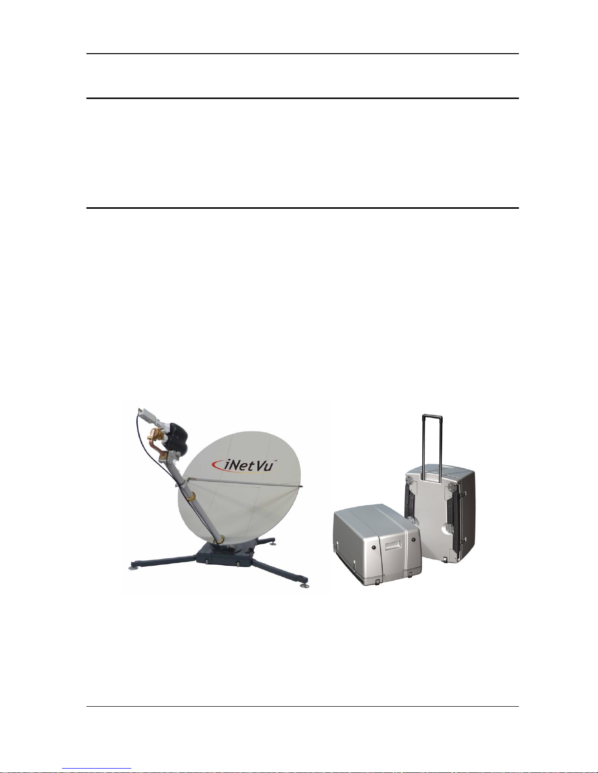
1.2. System Overview
Equipped to work with the iNetVu® 7000 Series Controller, the iNetVu® Airline Checkable
antenna is an easily assembled, highly portable unit and reliable product for automatic
satellite acquisition. This lightweight antenna is a rapidly deployable unit that is ideal for
applications that require satellite communication over Ku-Band. The Airline Checkable
empowers users with the ability to setup anywhere there exists satellite coverage and
access Internet at broadband speeds.
The Airline Checkable System comes with two (2) protective cases that have been
designed to be airline checkable just as the name implies. Without the use of any tools,
the Checkable system could be field assembled and operational in less than 10 minutes
by one person.
Fig. 1: iNetVu® 1210 (ACFLY-1200) Airline Checkable

C-COM Satellite Systems Inc. Page 6 of 50
iNetVu® Airline Checkable User Manual
1.3. General
All iNetVu® Airline Checkable Systems (ACFLY-1200) have been fully tested with the
iNetVu ® Controller prior to shipment. All position feedback; limit sensing, limit switches
and motor speeds have been calibrated and preset prior to shipping. The wave-guide, the
boom mounted Radio Transmitter cables and the Transmission/Receive coaxial cables
have all pre-wired. There is no need to re-calibrate the ACFLY-1200 Platform unless
directed by a C-Com Support Technician.
It is critical that the iNetVu® Controller stay together with the Flyaway Platform it shipped
with. You may refer to the iNetVu® Shipping Checklist to confirm this
The iNetVu® Airline Checkable system offers the following additional capabilities and
features:
• 3-Axes DC motor drive system.
• Highly reliable controls system.
• Satellite acquisition within 5 minutes (under normal operating conditions).
• Compatible with any configured satellite over the Ku Band.
• Fully automatic, software controlled satellite acquisition.
• Supports manual control when required.
• Optimized signal reception and transmission.
• Self-calibrating after satellite acquisition.
• Stand Alone – Satellite Acquisition via DVB (modem independent).
• Integrated with some of the leading satellite service providers available.
• Easily assembled, Airline Checkable light-weight carry gear.
1.4. Power Consumption
Minimum Power Consumption: 13W (when system is idle incl. internal drive
modules);
Maximum Power Consumption: 24@4.5A = 108W
Controller Voltage Range: 100 ~ 240VAC; Frequency Range: 50 ~ 60Hz
C-COM Satellite Systems Inc. Page 7 of 50
iNetVu® Airline Checkable User Manual
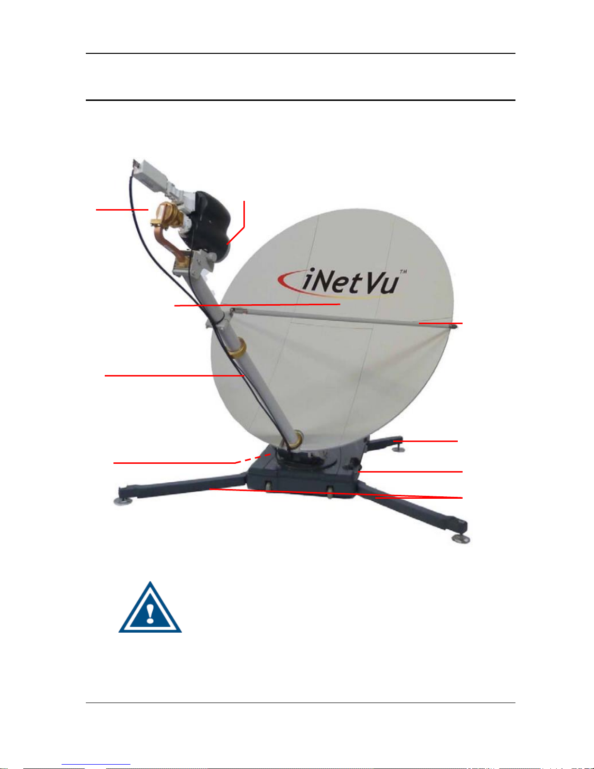
2. Physical Outline
WARNING!!!
Prior to operation you must use ballasts or anchors to
weigh down the fly-away at all times, failing to do so
may result in property or equipment damage.
6-piece detachable carbon
Fiber reflector
Front Stabilizing
Legs (2)
Polarization
Assembly & Motor
Feed Horn
Azimuth/ Elevation
Motor & Gear
Connection
Feed Arm Struts (2)
Polarization Motor
Connection
Back Stabilizing
Legs (2)
C-COM Satellite Systems Inc. Page 8 of 50
iNetVu® Airline Checkable User Manual
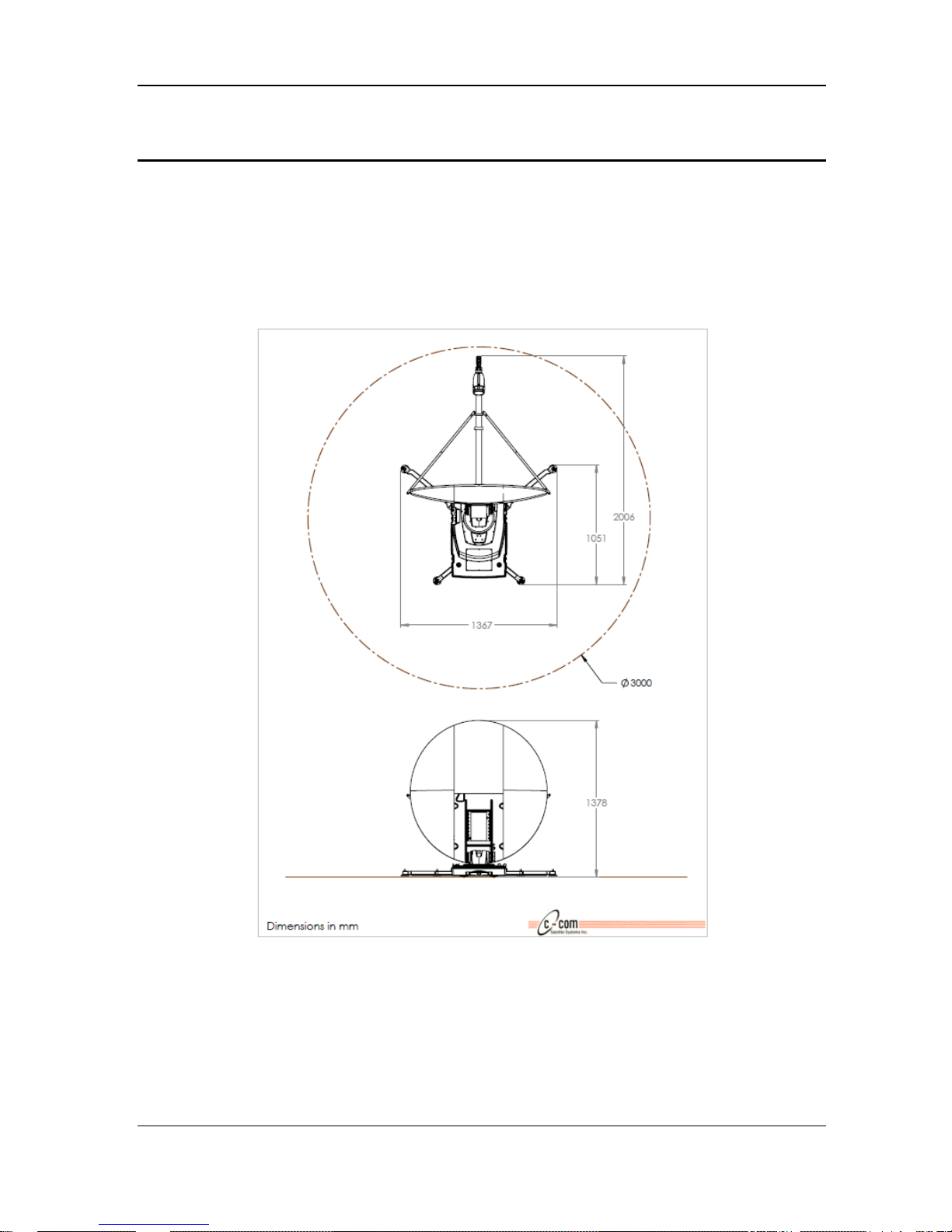
3. Clearance Requirements
All iNetVu® systems require a specific unobstructed clearance from any other equipment
or large obstacles that may hinder or prevent the system from acquiring satellite
communication.
A clear unobstructed view of the southern sky is required for reliable satellite
communication for users in the Northern Hemisphere. Vice versa for those in the Southern
Hemisphere
Fig. 2: iNetVu® 1210 Air Line Checkable Clearance dimensions
C-COM Satellite Systems Inc. Page 9 of 50
iNetVu® Airline Checkable User Manual
4. Assembly and Disassembly
4.1. Assembly Procedure
Base Support Stand Assembly
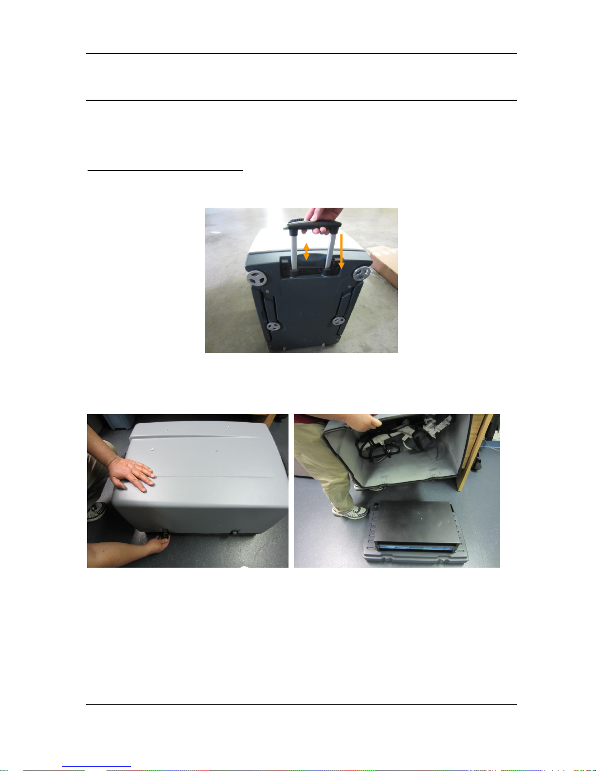
1) Fold and or slide the Airline Checkable pull handles back into holding place.
2) Setup Controller that is housed in the black case. Loosen clamps (2) by rotating latch
CCW (counter clockwise) and remove cover.
3) Place top section of case carefully aside as there are parts packed in it that will be
used later on.
4) Connect power to controller but do not turn it on at this point.
C-COM Satellite Systems Inc. Page 10 of 50
iNetVu® Airline Checkable User Manual
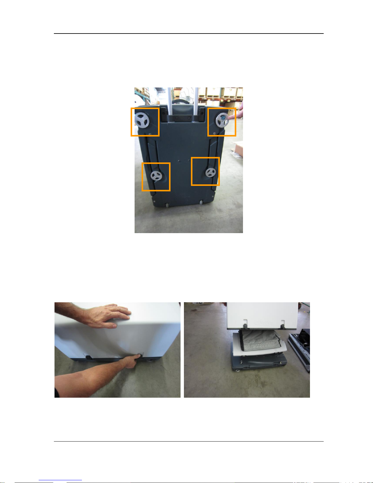
5) With antenna case sitting upright with the pull handle at the top, loosen the four (4)
legs so they can move in and out freely but do not pull or extend them out of place at
this stage.
6) Set Antenna case down on a flat surface using the pull handle as your reference to the
desired pointing direction the dish will face. The handle faces the back of the dish, so
roll the case into the preferred direction, tuck the handle in and set the case flat down.
7) Release the locking clips (4) to remove the top cover. Ensure top and bottom of the
clips release before attempting to remove cover.
C-COM Satellite Systems Inc. Page 11 of 50
iNetVu® Airline Checkable User Manual
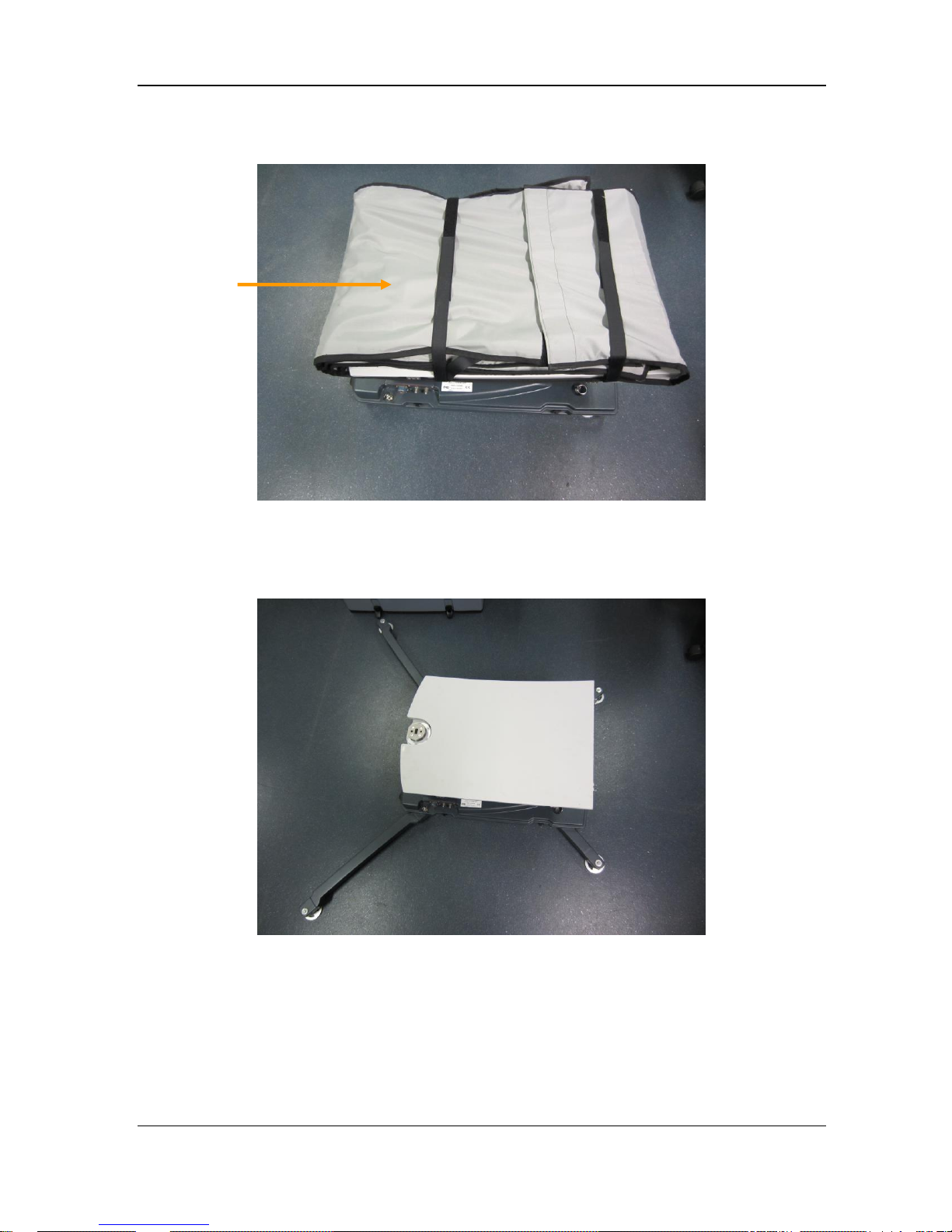
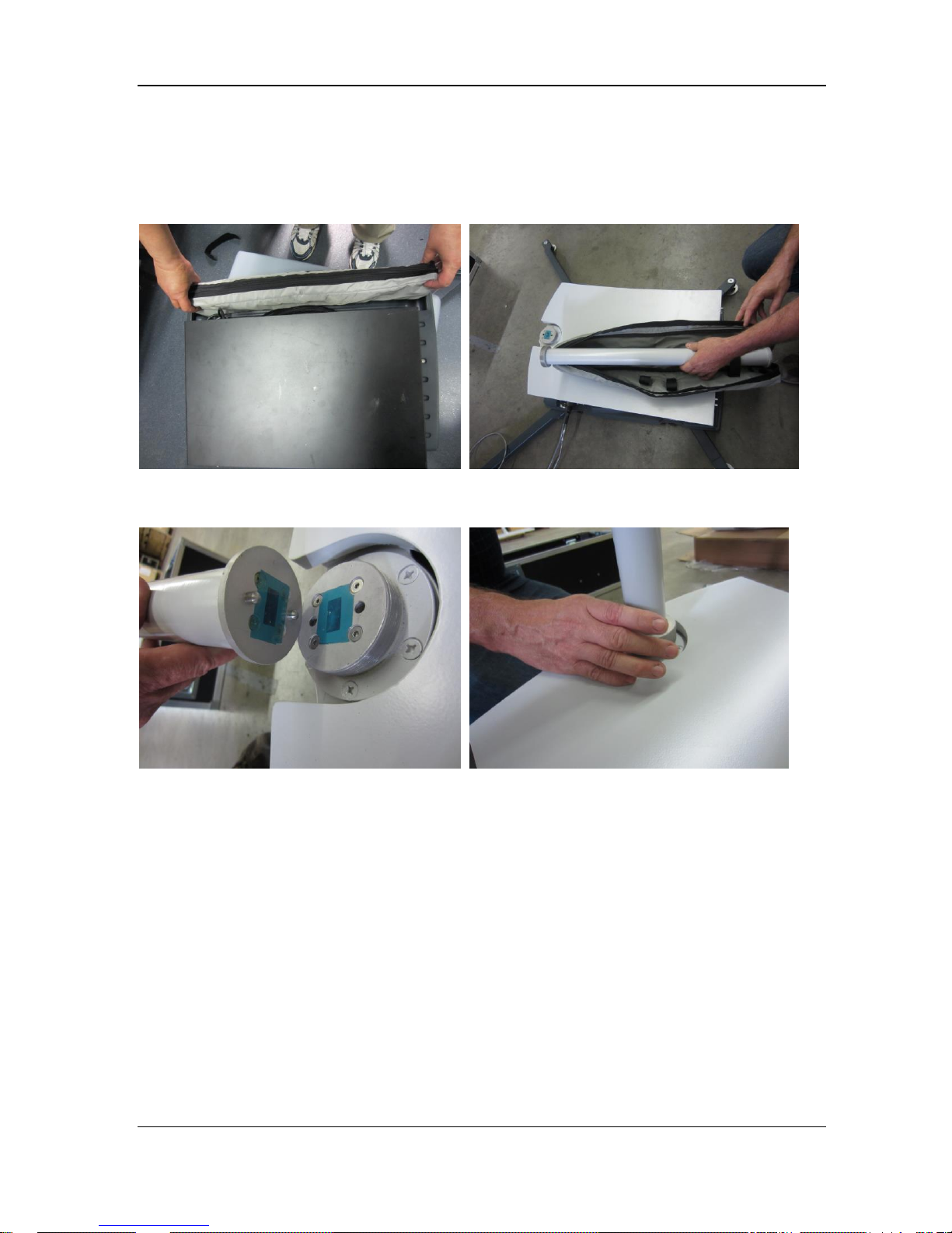
8) Remove reflector bag and set aside.
9) Pull out the (4) balancing legs; extend out until they click into place. The two (2)
shorter legs represent the back and the two (2) longer legs the front.
10) Remove rolled up cables from controller box.
Reflector
Bag
C-COM Satellite Systems Inc. Page 12 of 50
iNetVu® Airline Checkable User Manual
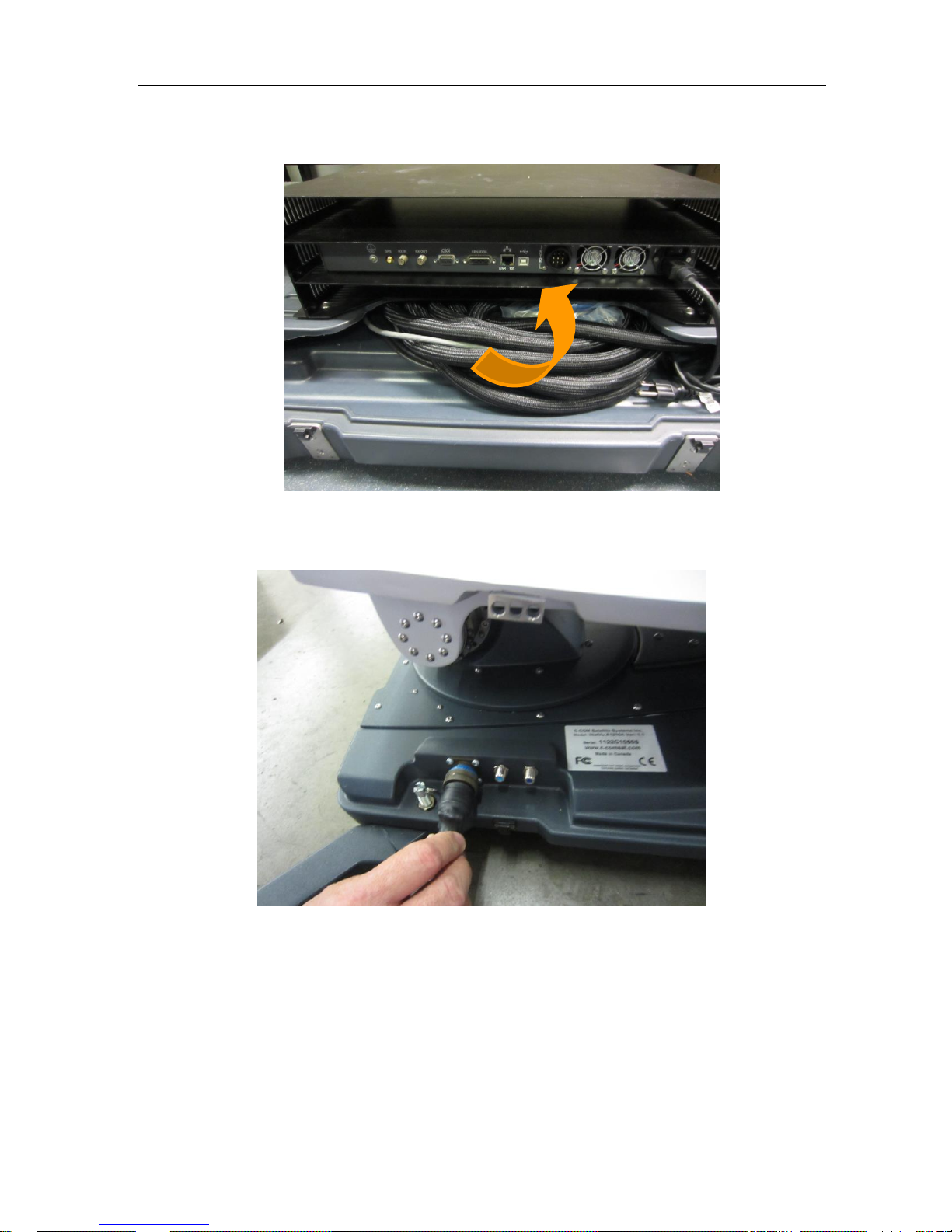
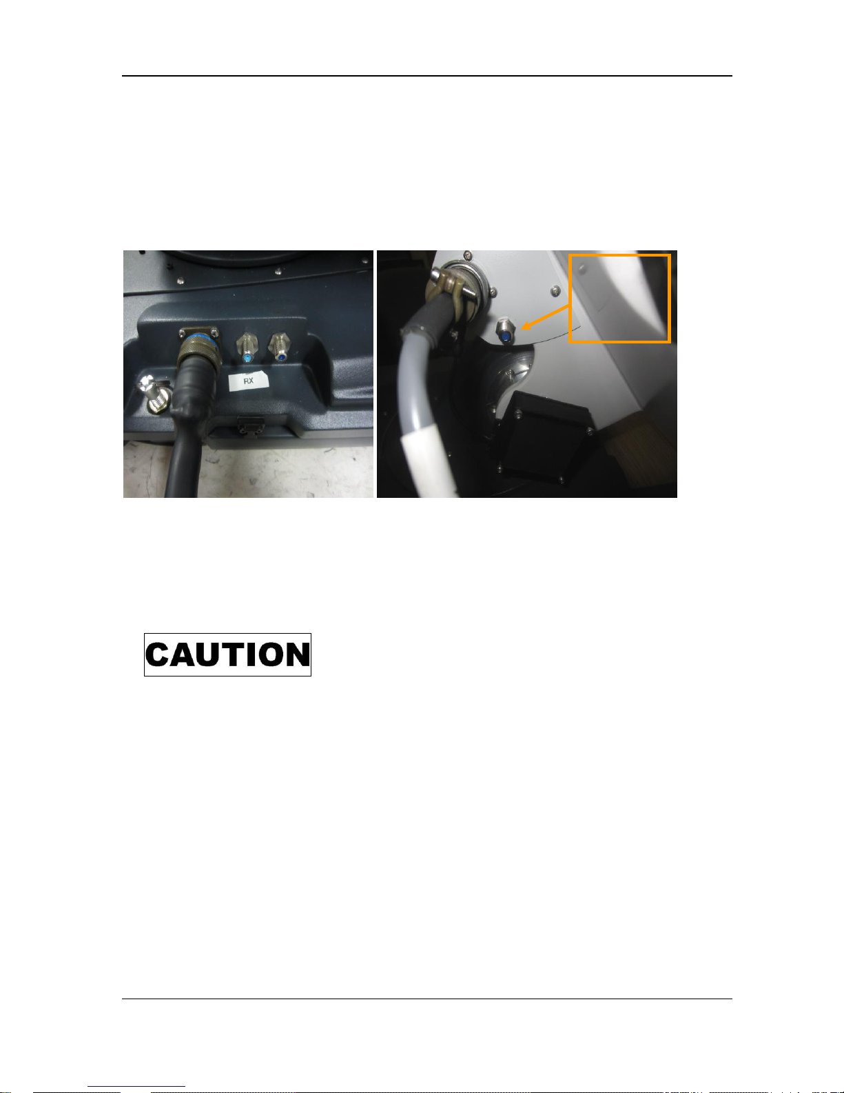
11) Connect cable to controller if not already connected.
12) Connect main cable from controller to antenna. Connector plate used for this
connection also has (2) coax connections (RX and TX).
**Note** There are two (2) identical connectors on the platform and these are not to be
confused with one another; one is used for the AZ, EL and the other is for the POL.
RX
TX
C-COM Satellite Systems Inc. Page 13 of 50
iNetVu® Airline Checkable User Manual
13) Remove and install Feedarm extension from controller housing case. Unzip bag and
remove extension. Install Feedarm extension as shown below and tighten turning CW
(clockwise) until tight.
Step 1. Remove Bag from case. Step 2. Remove extension from bag.
Step 3. Align pins with holes Step 4. Install extension

C-COM Satellite Systems Inc. Page 14 of 50
iNetVu® Airline Checkable User Manual
14) Remove POL Cage Assembly from case and connect to Feedarm extension,
15) Connect POL Cage Assembly cable to connection plate above tilt sensor.
POL
C-COM Satellite Systems Inc. Page 15 of 50
iNetVu® Airline Checkable User Manual
16) Connect Coaxial cables; there are 4 connections in total, 2 from external side, RX and
TX which are on the same face plate (on the base). The other 2 connections are an
extension of the RX and TX which come up from the hub and up the back of the
reflector base. Connect the cable labelled RX to the inside connection on the bracket
and the cable labelled TX goes to the BUC. The outer side of the bracket will have 2
connections one for the POL and the other is an RX that connects to the LNB.
17) Connect external GPS device to controller if one exists.
18) Power on Controller and launch the iNetVu software 7.5.3 + (7.5.3 is the minimal
version that is compatible with this antenna at the time of publication) ensure there are
no flashing Red or Yellow fields.
Indicates a situation or practice that might result in
property or equipment damage. Ensure Sensor and Motor
cables are connected or disconnected prior to powering
on/off 7000 Series Controller.
19) If Red or Yellow flashing fields are detected, stop and beginning troubleshooting.
20) Deploy Antenna to the following coordinates EL = 20, AZ = 0, and PL = 0. Refer to
iNetVu 7000 Series Controller Manual for more information on using the controller and
software. Section 5 in this document provides some information on the software and
its usage.
Coax
connection
from/to
LNB
TX
POL
RX
RX
 Loading...