

Troubleshooting Guide for iNetVu® 1201 Flyaway
The iNetVu™ brand and logo are registered trademarks of C-COM Satellite Systems, Inc. ©
Copyright 2006 C-C OM Satellite Sy stems, In c.
1-877-iNetVu6
www.c-comsat.com
Revision 01
January 01, 2013
iNetVu Troubleshooting Guide - 1201 Flyaway
Page 2 of 71
Copyright © 2010. All rights reserved. C-COM Satellite Systems Inc.
This document contains information, which is protected by copyright. All rights reserved.
Reproduction, adaptation, or translation without prior written permission is prohibited, except
as followed under the copy r i g ht law s.
Both the iNetVu™ and C-COM names and logos are registered trademarks of C-COM
Satellite Systems Inc.
Intel® Pentium is a registered trademark of Intel Corporation. Microsoft, Windows, Windows
NT and MapPoint are registered trademarks of Microsoft Corporation.
All other product names mentioned in this manual may be trademarks or registered
trademarks of their respective companies and are the sole property of their respective
manufacturers.

iNetVu Troubleshooting Guide - 1201 Flyaway
Page 3 of 71
FCC and INDUSTRY CANADA INFORMATION TO THE USER:
The FCC and Industry Canada have imposed the following conditions when operating,
installing and deploying iNetVu™ Mobile Earth Stations and is mandatory for all installations
made within the Continental United States and Canada as well as Hawaii, Alaska, Puerto
Rico, the U.S. Virgin Islands and other U.S. Territories. The FCC requires that a certified
installer perform the installation. It is also strongly recommended that a qualified professional
RV dealer/installer mount the system on your vehicle. These conditions are also required by
C-COM for all other installed locations.
All iNetVu™ Mobile earth station installers must be C-COM Certified, and must have
specifically acknowledged the requirements for iNetVu™ Mobile installations, which are as
follows:
“Installation” is the physical mounting and wiring of the Satellite provider’s earth station
on a vehicle or other stationary site in order to prepare for correct operation. Only Cer tified CCOM iNetVu installers may perform the installation and removal of an iNetVu™ Mobile
system.
“Deployment” means the raising, pointing and orienting of the earth station to the
communicating satellite, every time it is raised from a stowed position for use. The
deployment of an iNetVu™ Mobile system must only be done by a trained installer or by a
consumer using the deployment software.
Installers shall install the iNetVu™ systems only in locations that are not readily accessible to
children and in a manner that prevents human exposure to potential radiation hazards.
For large vehicles with roof mounts, the height of the bottom lip of the earth station when fully
deployed must be at least six feet above the ground at all times, or six feet above a
surrounding surface which a person may easily access.
If a roof access ladder or any other means of access to the roof is installed on the
vehicle, then the ladder or access must be blocked by a suitable rope or other barrier while
the earth station is deployed or in operation. The installer must provide this rope or barrier
directly to the end user at the time of installation and advise the user to use it at all times
when the earth station is deployed or in operation. Warning signs shall also be provided by
the installer to the end user to be posted on the rope or other barrier warning all persons not
to attempt to access the roof of the vehicle while the earth station is deployed or in operation.
Warning signs shall be posted at prominent locations on the earth station informing all
persons of the danger of harmful radiation from the earth station while it is deployed or while
in operation.
The iNetVu™ Mobile system may only be operated when the vehicle is stationary.
The installer must inform the end user that the vehicle must be stabilized during the
transmission, to prevent movement of the vehicle for any reason, including movement of
persons on or off the vehicle, or high winds. The installer shall advise the end user how to
appropriately stabilize their vehicle.
Installers shall be liable for all damages if they fail to comply with the above mandatory
conditions. This includes, but is not limited to damages caused by improper installation or
due to the failure to provide required information to the end user.
Installers and end users will be deemed directly liable for any damages resulting from either
of their failure to comply with the above rules. These rules are meant to ensure that

iNetVu Troubleshooting Guide - 1201 Flyaway
Page 4 of 71
extraordinary precautions and measures are used to prevent satellite interference or
exposure to harmful radiation. C-COM reserves the rights to immediately suspend without
liability or previous notice the operation of the earth station upon detection of a deviation
from its installation or operational requirements until the deviation is corrected. In addition, CCOM reserves the right to suspend or cancel the Installer Certificate of any installer that has
not fully complied with these installation requirements.
Further, the installer and end user may be directly liable for any damages resulting
from any change undertaken by either of them. Including but not limited to, any modification of
any part of the hardware, software, specific operational frequencies, the authorized satellite,
or the size or other characteristics of the earth station supplied to them by C-COM or CCOM’s authorized representatives.
Note 1:
This equipment has been tested and found to comply with the limits for a Class B digital
device, pursuant to Part 15 of FCC rules. These limits are designed to provide reasonable
protection against harmful interference when the equipment is operated in a residential
installation. This equipment generates, uses, and can radiate radio frequency energy and, if
not installed and used in accordance with this instruction manual, may cause harmful
interference with radio communications. However, there is no guarantee that interference will
not occur in a particular installation. If this equipment does cause harmful interference to
radio or television reception, which can be determined by turning the equipment off and on,
the user is encouraged to try to correct the interference by one or more of the following
measures:
Reorient or relocate the receiving antenna.
Increase the separation between the equipment and receiver.
Connect the equipment into an outlet on a circuit different from that to which the receiver is
connected.
Consult the dealer or an experienced radio / TV technician for help.
Note 2:
This Class B digital apparatus complies with Canadian ICES-003.

iNetVu Troubleshooting Guide - 1201 Flyaway
Page 5 of 71
C-Com Satellite Systems Global Headquarters
2574 Sheffield Road
Ottawa, Ontario, Canada
Phone: +1-613-745-4110
Fax: +1-613-745-7144
info@c-comsat.com
Dealer Information:
dealer@c-comsat.com
support@c-comsat.com
Phone: +1-613-745-4110 OPT2
Toll Free: 1-877-463-8886 OPT2
Monday – Friday, 8:30am – 6:00pm EST
After Hours Support:
Tel: 1-613-656-3723
Toll Free: 1-800-233-0218
Monday – Friday, 6:00pm – 9:00pm EST
Weekends an d Canadian Hol idays
8:30am – 9:00pm EST
K1B 3V7
General In q uiries:
Support Services:

iNetVu Troubleshooting Guide - 1201 Flyaway
Page 6 of 71
Table of Contents
INTRODUCTION ................................................................................................................................. 7
7000 CONTROLLER SOFTWARE & FIRMWARE UPGRADE ........................................................... 8
NINSTALLING THE CURRENT SOFTWARE ............................................................................................. 9
U
N
EW SOFTWARE AND DRIVERS INSTALLATION PROCEDURE ................................................................. 10
U
PDATING THE FIRMWARE ................................................................................................................. 13
V
ERIFYING THE UPGRADE COMPLETED SUCCESSFULLY ...................................................................... 14
S
ERIAL NUMBER IS LOCATED ON THE AZIMUTH BASE AND REFLECTOR ................................................... 14
ASSEMBLY AND DISASSEMBLY .................................................................................................... 15
LY-1201 PHYSICAL OUTLINE ............................................................................................................ 16
F
A
SSEMBLY PROCEDURE .................................................................................................................... 17
D
ISASSEMBLY PROCEDURE ............................................................................................................... 27
JAM ERRORS ................................................................................................................................... 37
RROR 0X9006 - EL JAM ERROR ....................................................................................................... 38
E
1. If the Mobile Platform doesn’t physically move ................................................................................................. 38
2. If the Mobile Platform physically moves but the angle doesn’t change......................................................... 40
E
RROR 0X9007 - AZ JAM ERROR ....................................................................................................... 42
1. If the Mobile Platform doesn’t physically move ................................................................................................. 42
2. If the Mobile Platform physically moves but the angle doesn’t change......................................................... 44
E
RROR 0X9008 - PL JAM ERROR ....................................................................................................... 46
1. If the Mobile Platform doesn’t physically move ................................................................................................. 46
2. If the Mobile Platform physically moves but the angle doesn’t change......................................................... 48
SENSOR ERROR .............................................................................................................................. 50
RROR 0X8911 - SENSOR ERROR ..................................................................................................... 51
E
GPS ................................................................................................................................................... 54
FAILED ..................................................................................................................................... 55
GPS
RF SIGNAL LOSS ............................................................................................................................. 57
ERR_0X8915:
RF
SIGNAL NOT BEING DETECTED (POWERING LNB FROM THE CONTROLLER) ..................................... 59
RF
SIGNAL NOT BEING DETECTED (POWERING LNB FROM THE MODEM) ............................................. 61
RF IS TOO LOW ...................................................................................................... 58
MODEM ............................................................................................................................................. 63
O MODEM COMMUNICATION ............................................................................................................ 64
N
2. To troubleshoot a COM configuration: ............................................................................................................... 65
3. To troubleshoot an IP (HTTP, TELNET, UDP, SNMP) configuration:........................................................... 66
CANNOT FIND SATELLITE .............................................................................................................. 67

iNetVu Troubleshooting Guide - 1201 Flyaway
Page 7 of 71
INTRODUCTION
About This Manual
This manual explains how to troubleshoot common errors on the iNetVu™ Mobile System. An
electronic version of this manual is available on the C-COM FTP and Knowledge Base.
iNetVu Troubleshooting Guide - 1201 Flyaway
Page 8 of 71
Minimum Requirements to run IMS Software
IMS Version
RAM
Processor Clock
Disk Space
Microsoft .NET Version
7.1.3 – 7.2.5
512 MB
800 MHZ
50 Megs Of Free Space
N/A
7.5.1 +
1 GB
2.0 GHZ
100 Megs Of Free Space
.
7000 CONTROLLER SOFTWARE & FIRMWARE UPGRADE
Quick Tip: The software and firmware versions must match for normal operation.
NET Framework 3.5
iNetVu Troubleshooting Guide - 1201 Flyaway
Page 9 of 71
Uninstalling the Current Software
Note: This method describes the steps for upgrading to and from the new .NET GUI interface ver.
7.5.x
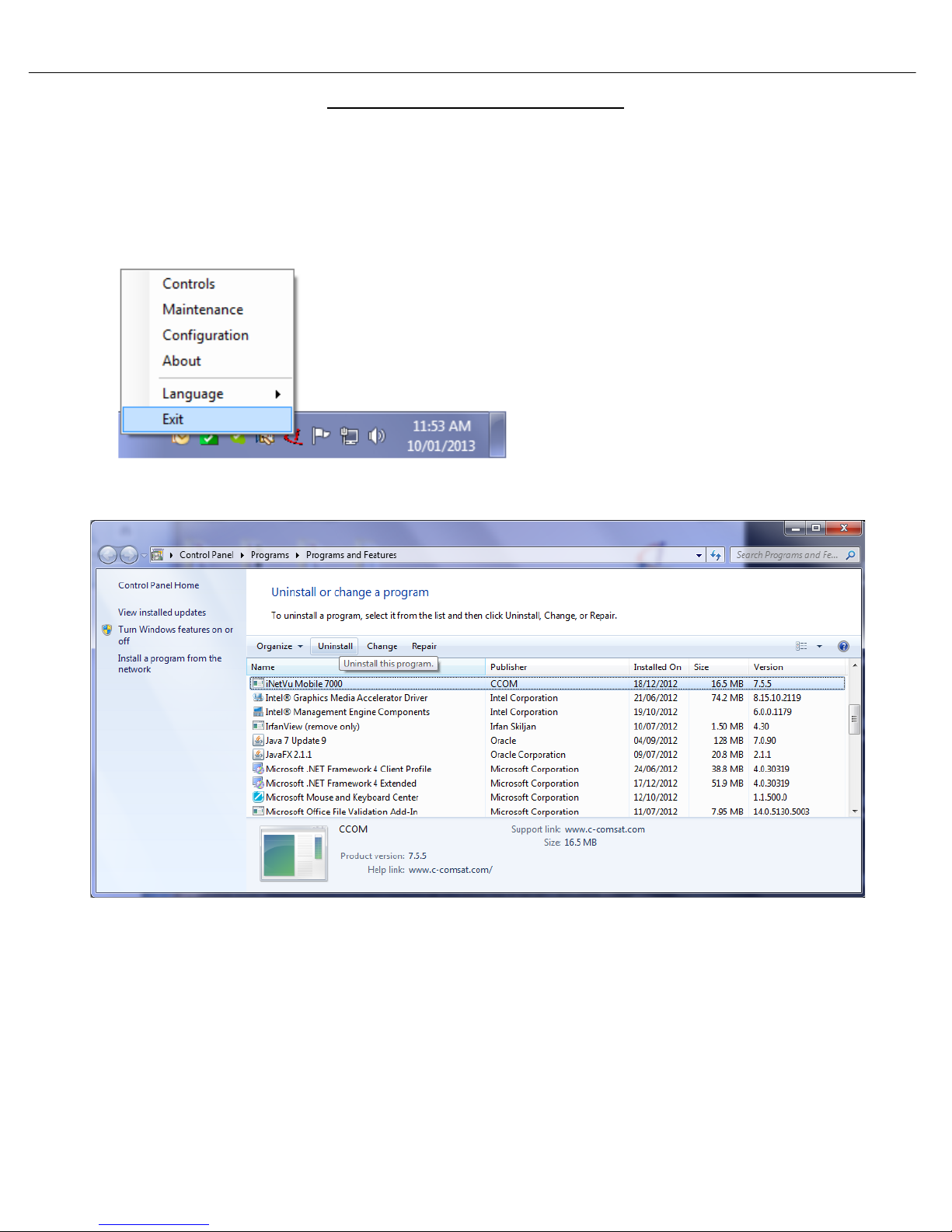
1. Ensure the iNetVu software is not running. If it is, right click the icon on the bottom right of the
screen and exit. As shown below.
2. Go to the Windows Control Panel and simply uninstall the iNetVu software.
iNetVu Troubleshooting Guide - 1201 Flyaway
Page 10 of 71
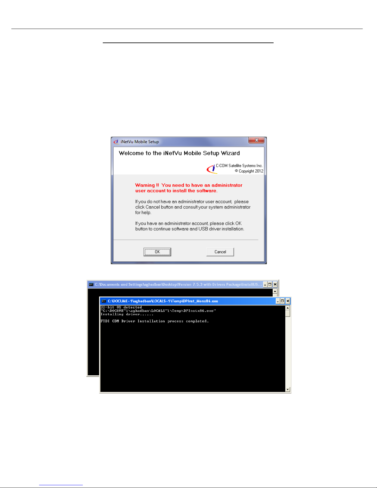
New Software and Drivers Installation Procedure
Applies to: iNetVu combined Software and Drivers Package version 7.5.5+
Note: Do not connect the Controller via USB until the drivers and software have been installed
1. If you are installing from the USB flash drive or have downloaded from the C-COM FTP, run
the iNetVuSetup.exe file.
2. Click OK to continue.
Administrator privileges are required
The driver Installation will be begin
Note: The Software Installation will begin automatically. Please complete the Device Driver Installation
Wizard before continuing with the iNetVu Software Installation.

iNetVu Troubleshooting Guide - 1201 Flyaway
Page 11 of 71
3. Continue through the Device Driver Installation Wizard.
Click “Next” Click “Continue Anyway”
4. Now continue through the iNetVu Software installation and close when complete. A new Icon
will automatically be placed on the Desktop.
5. Now that the drivers and software package has been installed, connect the iNetVu 7000
Controller via USB to your PC.
6. Windows XP users will have to follow the new hardware wizard and let windows automatically
install the drivers.
Click “Finish” to continue.

iNetVu Troubleshooting Guide - 1201 Flyaway
Page 12 of 71
Select “No, not this time” Select “Install the software automatically”
Click “Continue Anyway” Click “Finish”
7. Windows Vista and 7 users, the drivers should install automatically without any further user
action.
It’s normal for the 7000 driver to be displayed as iNetVu Controller 5000
8. You have successfully installed the 7000 iNetVu Drivers and Software. You can now continue
updating the Controller firmware.

iNetVu Troubleshooting Guide - 1201 Flyaway
Page 13 of 71
Updating the Firmware
1. Launch the iNetVu 7000 Mobile Software. Since the software is being upgraded, the Software and
Firmware will not match. Please follow the steps below to update the Firmware.
a) Once the controller is fully booted and the software is launched, the LCD should display what
is shown below. If your results differ, please contact C-COM Technical support.
Note: Screens may differ depending on Firmware. Ver. 7.5.5 shown below
b) Press and release the “Reset” button. While the controller is resetting hold the “↑” and “↓”
keypads simultaneously for 5 seconds to initiate the firmware update process.
c) The controller LCD should display what is shown below (IP will differ). If you did not achieve
this, please repeat step b)
d) The iNetVu software should now automatically switch to the “Maintenance” Screen. Once on
this page hit “Load Firmware” Please stand by for 45-60 seconds allowing the process to finish.
Do not power the controller off during this process.
Once completed the controller will restart
iNetVu Troubleshooting Guide - 1201 Flyaway
Page 14 of 71
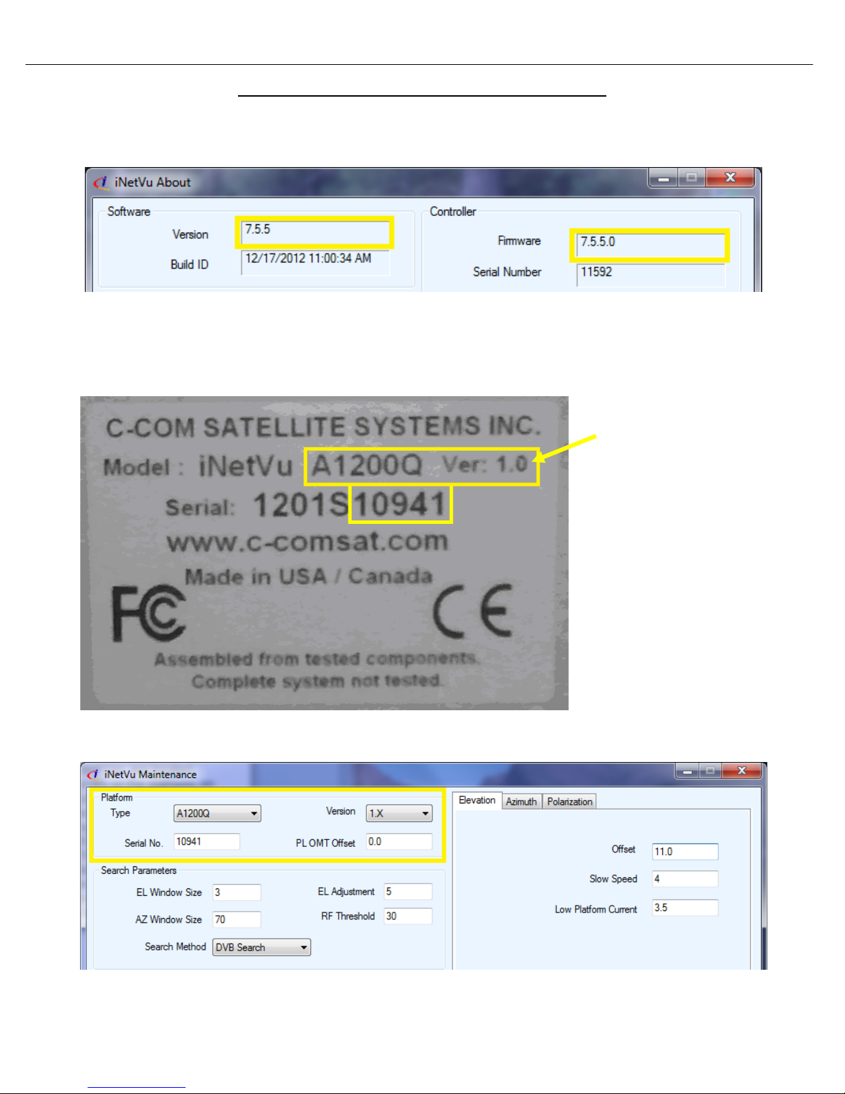
The platform serial number,
Verifying the Upgrade Completed Successfully
2. Right click on the current screen you are on, and select “About”. Verify both Software and
Firmware versions are identical.
3. After the firmware update has completed, proceed to the “Maintenance” screen and verify that the
platform type, Ver. and serial number match your platform. Make any necessary changes “Send
All” and wait for confirmation, then “Write EP ROM” “.
type and Ver. are loc ated
physically on the platform, on
the Azimuth Base and
Reflector. Looking at the
example below, we can see
the Model A1200Q, Ver. 1.0
and 10941 is the serial
number. The serial number
will be the last 4 or 5 digits.
Once we have obtained this
information, it must be
entered into the software.
Serial number is located on the azimuth base and reflector

iNetVu Troubleshooting Guide - 1201 Flyaway
Page 15 of 71
Assembly and Disassembly
iNetVu Troubleshooting Guide - 1201 Flyaway
Page 16 of 71
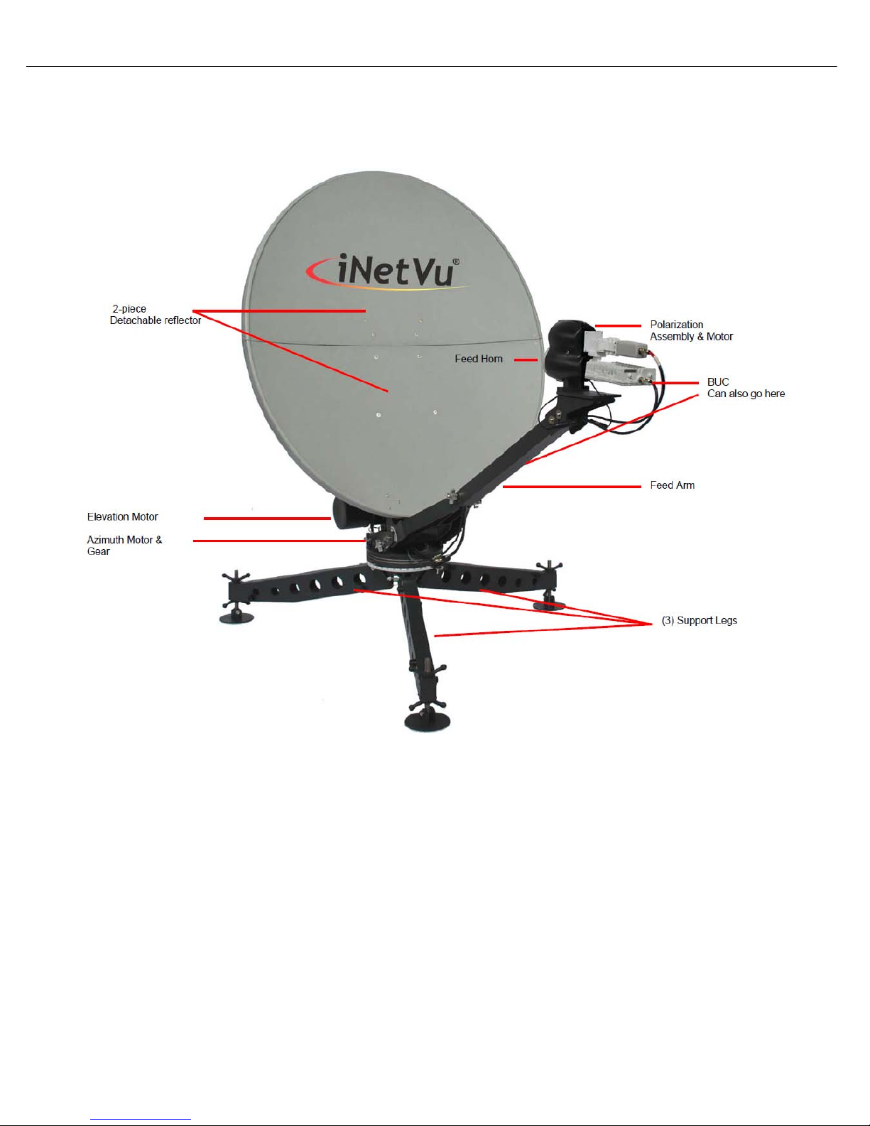
Fly-1201 Physical Outline
Page 17 of 71
iNetVu Troubleshooting Guide - 1201 Flyaway
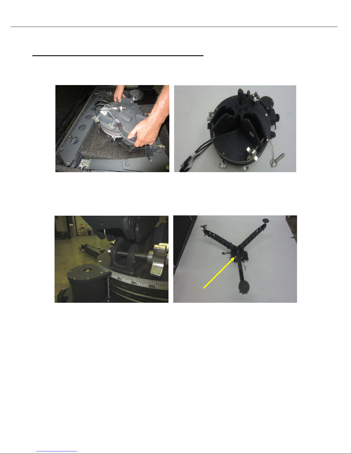
Assembly Procedure
Support Stand and EL Feed Arm Support plate Assembly
1) Remove AZ Assembly from the case and place it down with the leg grooves pointing to the sky as
depicted in the image.
2) Remove (3) legs from the case and install. One of the legs will have a label on it; this leg should be
installed at the 130 degree marking on the AZ base. The AZ base will also have stickers indicating
the install location of the back leg.

iNetVu Troubleshooting Guide - 1201 Flyaway
Page 18 of 71
Back Leg
3) Flip the AZ assembly over so it is sitting (like a tripod) on all (3) legs; the leg with the label (back
leg) should be pointing North (if located in Northern Hemisphere) and South (if location is in the
Southern Hemisphere).
4) Remove EL Feed Arm Support plate, fold arm brackets out as depicted in the image.
iNetVu Troubleshooting Guide - 1201 Flyaway
Page 19 of 71
Actuator
Motor
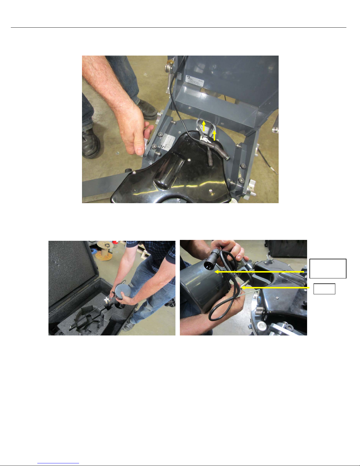
5) Install EL Feed Arm Support plate on the AZ base assembly; ensure the cables (POL and Coax)
are pulled through front opening and tighten the (4) retaining nuts.
6) Remove EL actuator assembly from the case; install bottom pin as shown making sure the
actuator motor is on the right hand side with reference to the back of the EL support plate.
iNetVu Troubleshooting Guide - 1201 Flyaway
Page 20 of 71
7) Supporting the actuator with your shoulder, connect the EL motor and EL tilt sensor cables by
aligning the notches to the white dash.
8) Lower the EL Feed Arm Support plate onto the EL Actuator and tighten retaining nuts.
iNetVu Troubleshooting Guide - 1201 Flyaway
Page 21 of 71
9) Open and remove Feed Arm from case.
10) Install Feed Arm onto EL Feed Arm Support plate and tighten retaining (2) nuts.
11) The BUC can be installed at this stage if not already installed. Follow the “Installing BUC with the
Universal Mounting Clamp kit” for mounting the BUC onto the mounting plate of the feed arm.
iNetVu Troubleshooting Guide - 1201 Flyaway
Page 22 of 71
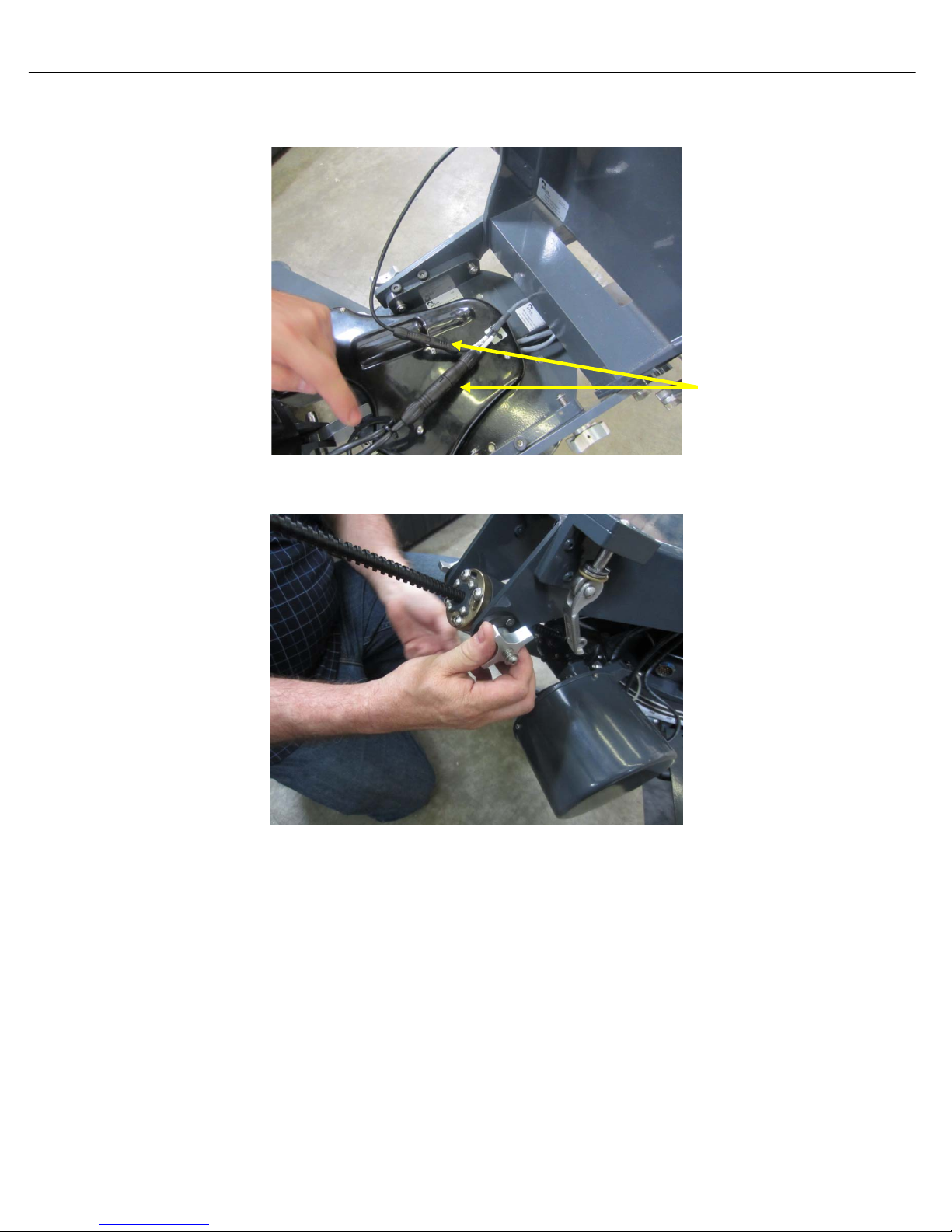
Motor/Sensor
12) Connect internal PL Motor, PL Tilt Sensor and RX/TX cables (coming from Feed arm) ensure to
align groves marked by the white dash.
13) Open Reflector case and remove External Motor and Sensor cable.
Cable

iNetVu Troubleshooting Guide - 1201 Flyaway
Page 23 of 71
Indicates a situation or practice that might result in
7000 Series Controller.
property or equipment damage. Ensure Sensor, Motor
and RX/TX cables are connected prior to powering on
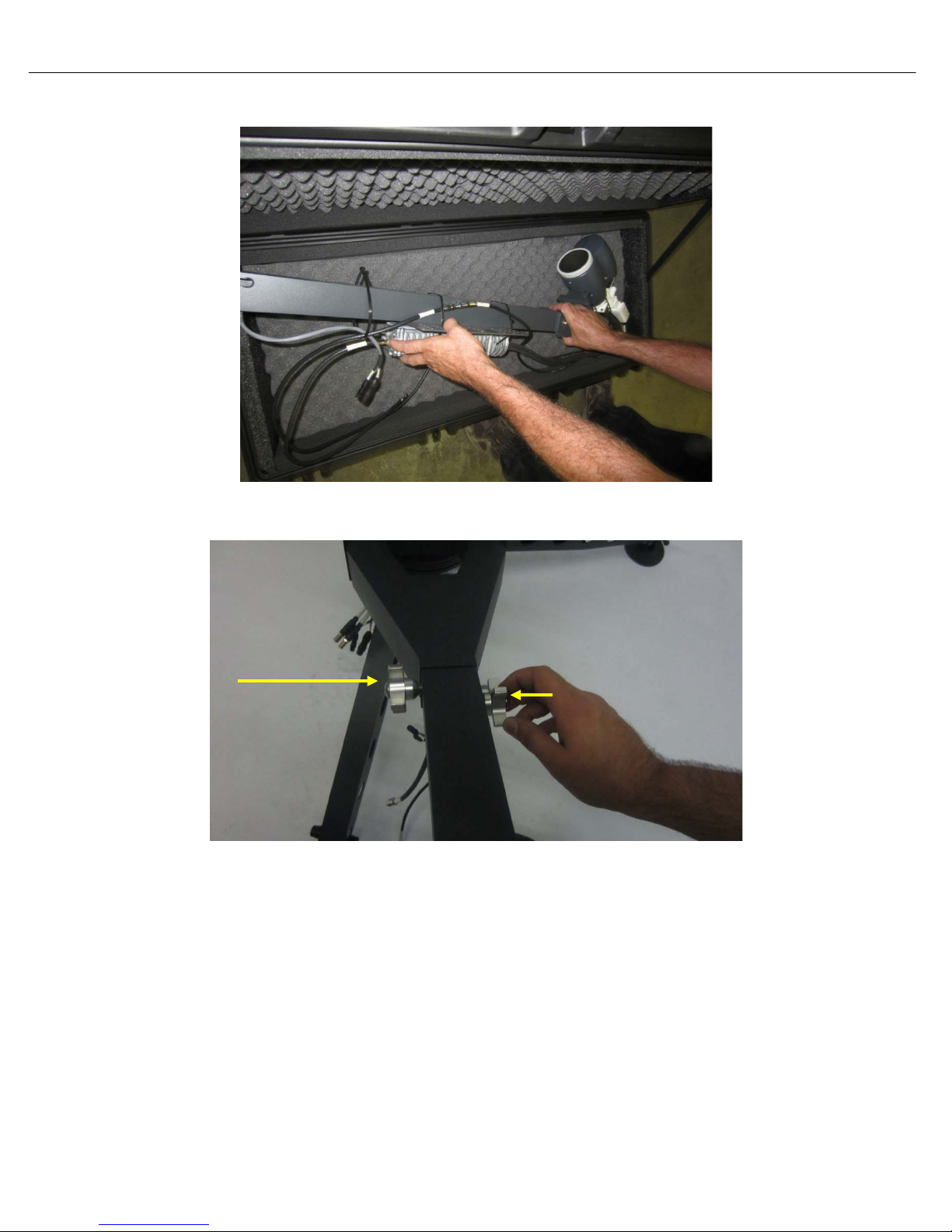
14) Connect External Motor and Sensor cable to AZ mount base. Line up the biggest notch on the
connector to be at the top before attempting to connect to mount face plate.
15) Turn connector CW (clockwise) until it snaps into place, and a click is heard. Connect as well the
RX and TX coax cables. Note TX is the top and RX the bottom connector as the label on the plate
indicates.

iNetVu Troubleshooting Guide - 1201 Flyaway
Page 24 of 71
16) Connect cable labelled TX to BUC and RX to LNB.
17) Open Controller box (if applicable) back cover and connect external cables (Motor, Sensor and
RX/TX cables). Also connect power, USB and LAN cable if required.
18) Power on iNetVu
®
controller and launch iNetVu® software on your computer/laptop. There should
be no blinking or RED fields on the Controls screen.

iNetVu Troubleshooting Guide - 1201 Flyaway
Page 25 of 71
Bottom
Top
19) Deploy the Antenna to the following coordinates, EL 30.0, AZ 0.0 and PL 0.0(Antenna fields are
set to these by default); this can be achieved by the software or controller front panel.
20) Open and remove bottom reflector from case. The bottom reflector section is the outer most with
reference to you. Refer to sticker inside the case for more details.
Section
Section
21) Attach the bottom reflector section to the EL Support Plate assembly making sure the bottom (2)
pins are in place first followed by the top (2), push and turn to lock.

iNetVu Troubleshooting Guide - 1201 Flyaway
Page 26 of 71
22) Attach the top reflector section to bottom section, align holes on bottom and top. Push in (3)
locking pins and clamp down handle.
23) Lock the reflectors together using the three (3) latches on the back and on both sides of the
reflector.
24) See section 4) for controller connectivity based on your desired connection preferences.
25) Congratulations, you have successfully assembled the iNetVu
®
Flyaway System and are ready for
Satellite search!

iNetVu Troubleshooting Guide - 1201 Flyaway
Page 27 of 71
Back of
Disassembly Procedure
1) Click deploy Antenna icon on the iNetVu Controls screen. Antenna should deploy to EL=30,
AZ=0 and PL=0.
Reflector Assembly Removal
2) Unhook the three (3) latches holding the two-piece reflector together, and detach the top
refle ctor assembly
3) Place top reflector in packaging case as shown in the image; note the positioning of the back
and front of the reflector section in reference to the way it sits in the case.
Reflector
4) Detach the bottom section of the reflector, there are (4) locking retaining clamps to loosen.

iNetVu Troubleshooting Guide - 1201 Flyaway
Page 28 of 71
5) Place bottom reflector section in the packaging case, close and lock the case.

iNetVu Troubleshooting Guide - 1201 Flyaway
Page 29 of 71
Polarization and Feed Arm Assembly Removal
6) Click/push Stow icon/button, the Antenna should go to the following coordinates:
EL=78, AZ =-60 and PL=0.
7) Power off the 7000 Series controller.
Ensure to power off the 7000 Series Controller prior to
disconnecting cables.
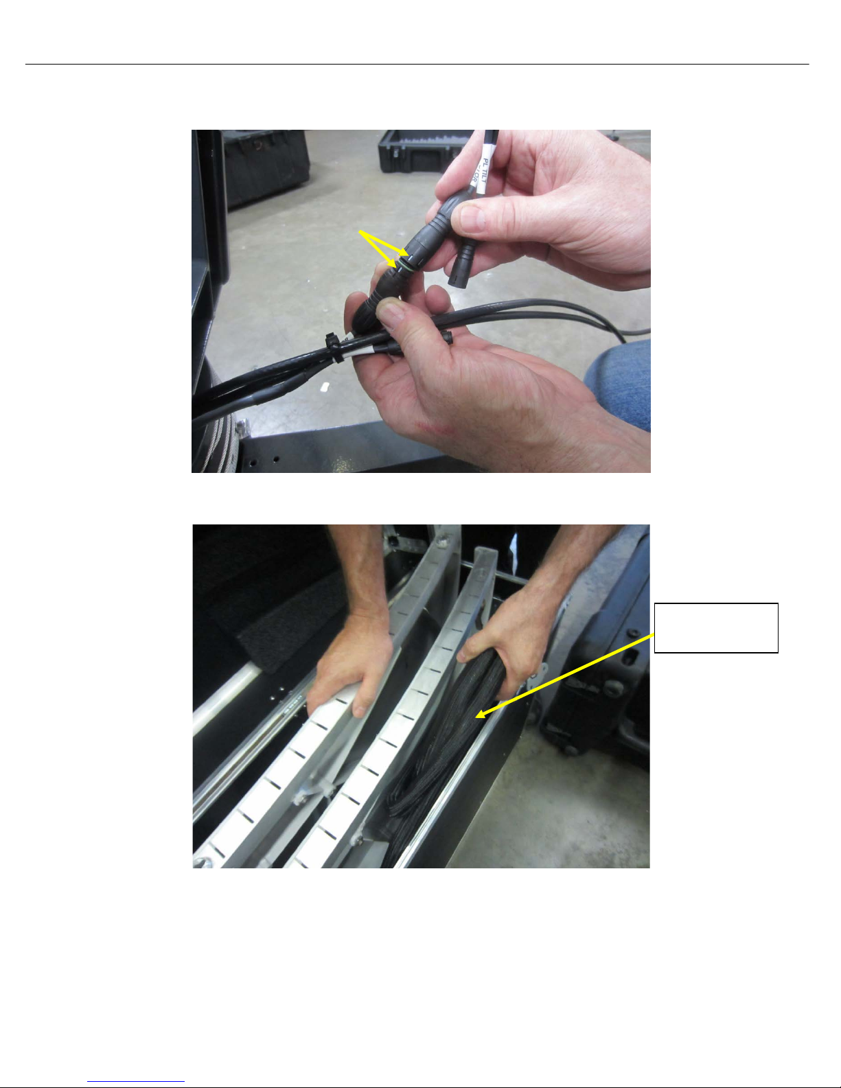
8) Disconnect the internal PL Tilt Sensor, PL Motor cable and LNB RX coax cable on the Feed
Arm.
9) Loosen retaining nuts; detach the Feed Arm and POL Cage assembly from the EL Feed Arm
Support plate.

iNetVu Troubleshooting Guide - 1201 Flyaway
Page 30 of 71
10) Place the Feed Arm in the protective case.
EL Feed Arm Support Plate and EL Actuator/Motor Assembly Removal
11) Loosen (2) retaining nuts on the EL Actuator, take extra care as the weight of the EL Support
plate is also supported by these retaining screws.

iNetVu Troubleshooting Guide - 1201 Flyaway
Page 31 of 71
12) With one hand on the EL Actuator/Motor and the other on the Support Plate, push forward on
the Support Plate to disengage the EL Actuator. Allow the EL support plate to lean forward.
13) Disconnect all cables (Motor/Sensor, TX and RX).
14) Remove the Quick Release T-Pin attaching the elevation motor assembly to the AZ base;
ensure to hold the actuator while removing the pin.

iNetVu Troubleshooting Guide - 1201 Flyaway
Page 32 of 71
15) Place the EL Actuator/Motor in the protective case.
16) Loosen (4) retaining nuts on the EL Support plate assembly. Remove EL Support Plate from
the AZ base.

iNetVu Troubleshooting Guide - 1201 Flyaway
Page 33 of 71
17) Fold brackets on the EL Support plate and place in protective case as shown.
18) Ensure the retaining nuts are retracted back and the reflector locking clamps are properly
tucked in (especially the bottom), for the EL Support plate to fit in the packing case; failing to
do so may prevent the case lid from closing.
AZ and Leg Assembly Removal
19) Loosen the retaining nuts on the (3) legs. Remove one leg at a time by tipping up the AZ
assembly and pushing down on the leg.

iNetVu Troubleshooting Guide - 1201 Flyaway
Page 34 of 71
20) Place legs in the protective case; ensure the feet are folded with the flat surface facing down.
21) Place the AZ base in protective case.

iNetVu Troubleshooting Guide - 1201 Flyaway
Page 35 of 71
22) Coil up the Motor/Sensor external cable and place in reflector protective case or controller
case.

iNetVu Troubleshooting Guide - 1201 Flyaway
Page 36 of 71
Closing and locking Cases
1) Close and lock latches shut on all (4) cases.
1. Reflector case 2. Feed Arm case
3. Controller case 4. AZ base and EL actuator case
2) Congratulations you have successfully packaged the iNetVu
®
Fly-1201Flyaway System.

iNetVu Troubleshooting Guide - 1201 Flyaway
Page 37 of 71
JAM ERRORS
Note: The key to troubleshooting a Jam Error is to determine whether this is a Sensor or Mechanical
issue.

iNetVu Troubleshooting Guide - 1201 Flyaway
Page 38 of 71
Error 0x9006 - EL Jam Error
1. If the Mobil e Platform doesn’t physically move
Possible Causes:
• 7000 Controller
• 15 Amp Fuse
• Flyaway Control Cable
• Internal Wiring
• Elevation Motor (actuator)
a. Verify if 7000 Controller is outputting 24VDC. Disconnect the motor cable from the back of the
controller, place the volt meter leads on pins 1 and 3 of the controller. Using the 7000 controllers
front panel, select Elevation with HI SPEED on and hold +. Are you getting 24VDC?
b. If we are not getting voltage from the 7000 controller, please turn off the controller and verify
the 15A fuse has not blown. If the fuse is blown replace it and try again. If the fuse is not blown,
contact C-COM Technical Support for further assistance.
Warning High Voltage: Always remove power from the 7000 Controller prior to removing fuse.
Failing to do so can result in personal injury or damage to the controller.

iNetVu Troubleshooting Guide - 1201 Flyaway
Page 39 of 71
c. If we are getting voltage from the 7000 controller, we will need to test voltage on the flyaway
control cable. Reconnect the motor cable to the controller and disconnect the control cable from
the base plate of the platform. Place the volt meter leads on pins C and D of the control cable.
Using the 7000 controllers front panel, select Elevation with HI SPEED on and hold +. Are you
getting 24VDC? If no voltage is shown, it concludes the cable needs to be replaced. Contact CCOM Technical Support for further assistance.
d. If we are getting voltage from the control cable, reconnect the Control Cable to the platform
and verify the Elevation Motor cable is securely connected as seen below.
Internal Elevation Motor and Tilt (Inclinometer) Sensor Cables
e. Reseat this cable and try to move the platform on elevation. If the platform does not move please
Contact C-COM Technical Support for further assistance.

iNetVu Troubleshooting Guide - 1201 Flyaway
Page 40 of 71
2. If the Mobile Platform physically moves but the angle doesn’t change
Possible Causes:
• 7000 Controller
• Flyaway Control Cable
• Internal Wiring
• Inclinometer (Tilt Sensor)
a. Please ensure the Flyaway Control Cable is securely connected to the 7000 Controller and
Platform. Reseat this cable at both ends and try again.
b. Try reseating the EL TILT cable as seen below.
Internal Elevation Tilt (Inclinometer) and Motor Cables
c. If the angle still does not change use the Sensor Circuit Diagram on the following page to
confirm continuity of the Control Cable. Set the voltmeter to beeper or continuity mode. If the
Control Cable passes continuity the inclinometer may have failed. Please Contact C-COM
Technical Support for further assistance.
Sensor Continuity Test

iNetVu Troubleshooting Guide - 1201 Flyaway
Page 41 of 71
Flyaway Control Cable

iNetVu Troubleshooting Guide - 1201 Flyaway
Page 42 of 71
Error 0x9007 - AZ Jam Error
1. If the Mobile Platform doesn’t physically move
Possible Causes:
• 7000 Controller
• 15 Amp Fuse
• Flyaway Control Cable
• Internal Wiring Harness
• Azimuth Motor
a. Verify if 7000 Controller is outputting 24VDC. Disconnect the Motor cable from the back of the
controller, place the volt meter leads on pins 7 and 9 of the controller. Using the 7000 controllers
front panel, select Azimuth with HI SPEED ON and hold +. Are you getting 24VDC?
b. If we are not getting voltage from the 7000 controller, please turn off the controller and verify
the 15A fuse has not blown. If the fuse is blown replace it and try again. If the fuse is not blown,
contact C-Com Technical Support for further assistance.
Warning High Voltage: Always remove power from the 7000 Controller prior to removing fuse.
Failing to do so can result in personal injury or damage to the controller.

iNetVu Troubleshooting Guide - 1201 Flyaway
Page 43 of 71
c. If we are getting voltage from the 7000 controller, we will need to test voltage on the Control
Cable. Reconnect the Motor Cable to the controller and disconnect the Control Cable from the
base plate of the Platform. Place the volt meter leads on pins A and B of the control cable. Using
the 7000 controllers front panel, select Azimuth with HI SPEED ON and hold +. Are you getting
24VDC? If no voltage is shown, it concludes the Control Cable needs to be replaced. Contact CCom Technical Support for further assistance.
d. If we are getting voltage from the control cable, this indicates we may have an Azimuth Motor
or Internal Wiring issue. Please contact C-Com Technical Support for further assistance.

iNetVu Troubleshooting Guide - 1201 Flyaway
Page 44 of 71
2. If the Mobile Platform physically moves but the angle doesn’t change
Possible Causes:
• 7000 Controller
• 15 Amp Fuse
• Flyaway Control Cable
• Internal Wiring
• Azimuth Potentiometer
a. Please ensure the Flyaway Control Cable is securely connected to the 7000 Controller and
Platform. Reseat this cable at both ends and try again.
b. If you are still experiencing issues please use the Sensor Circuit Diagram on the following page to
confirm continuity of the Control Cable. Set the voltmeter to beeper or continuity mode. If the
Control Cable passes continuity, this will conclude the issue is the Azimuth Encoder or Internal
Wiring. Please contact C-COM Technical Support for further assistance.
Sensor Continuity Test

iNetVu Troubleshooting Guide - 1201 Flyaway
Page 45 of 71
Flyaway Control Cable

iNetVu Troubleshooting Guide - 1201 Flyaway
Page 46 of 71
Error 0x9008 - PL Jam Error
1. If the Mobile Platform doesn’t physically move
Possible Causes:
• 7000 Controller
• 5 Amp Fuse
• Flyaway Control Cable
• Internal Wiring
• Polarization Motor
a. Verify if 7000 Controller is outputting 24VDC. Disconnect the motor cable from the back of the
controller, place the volt meter leads on pins 4 and 6 of the controller. Using the 7000 controllers
front panel, select Polarization with HI SPEED ON and hold +. Are you getting 24VDC?
b. If we are not getting voltage from the 7000 controller, please turn off the controller and verify
the 5A fuse has not blown. If the fuse is blown replace it and try again. If the fuse is not blown,
contact C-Com Technical Support for further assistance.
Warning High Voltage: Always remove power from the 7000 Controller prior to removing fuse.
Failing to do so can result in personal injury or damage to the controller.

iNetVu Troubleshooting Guide - 1201 Flyaway
Page 47 of 71
c. If we are getting voltage from the 7000 controller, we will need to test voltage on the Control
Cable. Reconnect the motor cable to the controller. Disconnect the Control Cable from the base
plate of the platform. Place the volt meter leads on pins E and F of the Control Cable. Using the
7000 controllers front panel, select Polarization with HI SPEED ON and hold +. Are you getting
24VDC? If no voltage is shown, it concludes the Control Cable needs to be replaced. Contact CCom Technical Support for further assistance.
d. If we are getting voltage from the controller cable, reconnect the Control Cable to the platform.
e. Verify the Polarization Motor Cable is securely connected and the two white groves align as seen
below.
Polarization Motor Cables
f. Reseat this cable and try to move the platform on Polarization. If the platform does not move the
Polarization motor may have failed. Contact C-Com Technical Support for further assistance.

iNetVu Troubleshooting Guide - 1201 Flyaway
Page 48 of 71
2. If the Mobile Platform physically moves but the angle doesn’t change
Possible Causes:
• Polarization Tilt Sensor (inclinometer)
• Sensor Cable
• Internal Wiring
• 7000 Controller
a. Please ensure the Flyaway Control Cable is securely connected to the 7000 Controller and
Platform. Reseat this cable at both ends and try again
b. Verify the Polarization Tilt Sensor Cable is securely connected as seen below. Try reseating this
cable. If the angle still does not update proceed to the next step.
Polarization Tilt Sensor Cable
c. Use the Sensor Circuit Diagram on the following page to confirm continuity of the Control Cable.
Set the voltmeter to beeper or continuity mode. If the Control Cable passes continuity, this will
conclude the issue is the Polarization Tilt Sensor or Internal Wiring. Please contact C-COM
Technical Support for further assistance.
Sensor Continuity Test

iNetVu Troubleshooting Guide - 1201 Flyaway
Page 49 of 71
Flyaway Control Cable

iNetVu Troubleshooting Guide - 1201 Flyaway
Page 50 of 71
SENSOR ERROR

iNetVu Troubleshooting Guide - 1201 Flyaway
Page 51 of 71
Error 0x8911 - Sensor Error
Cause:
1. The sensor cable is not connected properly or the pins on the sensor connector are bent,
broken or corroded.
2. Default Limits have been modified or are outside a valid range.
3. Possible failed components.
• Azimuth Encoder
• Polarization Tilt Sensor
• Internal Wiring
• Flyway Control Cable
• 7000 Controller
Solution:
1. Ensure that the sensor cable from the Controller and Platform side is properly connected and
not damaged. Ensure the internal wiring is properly connected. Try reseating these cables.
If this does not resolve your issue proceed to the next step.
2. Reselect the Platform Type to reset all Default Speeds and Limits.
a. Disconnect the Sensor cable from the Controller. Using the manual controls visually move
the platform on PL and AZ to the center position. ( you must visually verify as the
sensor readings will be unreliable)
b. Reconnect the sensor cable.
c. From the Maintenance menu, select a different Platform type than the current. Send All.
d. Select the correct Platform Type click “Send All” then “Write EPROM”.

iNetVu Troubleshooting Guide - 1201 Flyaway
Page 52 of 71
e. From the Controls Screen the AZ and PL Angles should be close to 0.00 as seen below.
f. If the angles are still incorrect or flashing Red/Yellow, proceed to the next step.

iNetVu Troubleshooting Guide - 1201 Flyaway
Page 53 of 71
3. Testing the Continuity of the Sensor Cable
Use the Sensor Circuit Diagram on the following page to confirm continuity of the Control Cable. Set
the voltmeter to beeper or continuity mode and test the Control Cable for continuity. Please contact CCOM Technical Support for further assistance.
Flyaway Control Cable

iNetVu Troubleshooting Guide - 1201 Flyaway
Page 54 of 71
GPS

iNetVu Troubleshooting Guide - 1201 Flyaway
Page 55 of 71
GPS Failed
Cause 1:
GPS Cable is not connected.
Solution 1:
Verify GPS cable is securely connected.
Cause 2:
A foreign object is obstructing the GPS Antenna.
Solution 2:
Ensure there are no foreign objects obstructing the GPS antenna from a clear view of the sky.
Cause 3:
Overcharge in the GPS Antenna.
Solution 3:
Turn off the Controller Unplug GPS connector from the back of the Controller and ground it. Wait 5
seconds. Re-connect GPS antenna and turn on the Controller. Observe the GPS Coordinates on the
Controls menu. It may take a couple of minutes to update.
Cause 4:
The Controllers GPS port or the GPS has failed.
Solution 4:
Test the Controllers GPS port for 3 Volts. If you are not getting any Voltage then the controller is the
issue. If you are getting Voltage the GPS Antenna is the issue. Please contact C-COM Technical
Support for further assistance.
Insert a wire or paperclip for better contact

iNetVu Troubleshooting Guide - 1201 Flyaway
Page 56 of 71
For emergency deployment the GPS can be overridden and the LAT/LONG entered manually
from the iNetVu 7000 Software or Web Interface.
iNetVu 7000 Software
7000 Controller Web Interface

iNetVu Troubleshooting Guide - 1201 Flyaway
Page 57 of 71
RF SIGNAL LOSS

iNetVu Troubleshooting Guide - 1201 Flyaway
Page 58 of 71
RF Signal in Yell ow/Red:
RF Signal in Cyan/Blue Color: (Normal
Status Definitions:
(Abnormal Sate)
This indicates the controller is not
detecting power at the LNB. You will
be unable to deploy the dish in this
state and will receive ERR_0x8915:
RF is too low.
Step 1:
• Verify the physical RX connections are properly connected by referring to the diagrams below.
Powering the LNB from the 7000 Controller
• If the RX connection was corrected, please refer to the Controls screen to determine if the RF
signal is in a normal state.
• If RF is still in YELLOW/RED contin ue troubleshooting your configuration.
ERR_0X8915: RF IS TOO LOW
State)
This indicates the controller is detecting
power at the LNB which is normal
behavior. The value should always be in
this color format whether the unit is off or
on satellite. The value itself will
decrease/increase but our main focus is
to always have it in this state.
Powering LNB from the Controller
Powering LNB from the Modem
Powering the LNB from the Modem

iNetVu Troubleshooting Guide - 1201 Flyaway
Page 59 of 71
RF Signal Not Being Detected (Powering LNB from the Controller)
Step 2:
• Verify that the correct “LNB Power” voltage is selected in the iNetVu “Configuration” screen.
• If the incorrect voltage was selected or the option was disabled, please make the necessary
changes and click “Send All” then “Write EPROM” for the changes to take effect.
• If the RF signal is still flashing in RED and YELLOW, please proceed to step 3.
Step 3:
• Disconnect the coax from the “RX IN” port on the back of the controller and measure voltage
on the connector.
• If no voltage is shown or the voltage is not equal to what is selected in the “Configuration”
screen, contact C-COM Technical Support as the controller will need to be repaired.
Alternatively you may attempt to power the LNB from the modem until a replacement controller
has arrived. Please refer to the 7000 Series Controller Manual for more information.
• If voltage is shown and corresponds to the voltage selected in the “Configuration” Screen”
proceed to step 4.

iNetVu Troubleshooting Guide - 1201 Flyaway
Page 60 of 71
Step 4:
• Disconnect the coax cable going into the “RX” port on the base plate of the antenna.
• Measure voltage on this cable. If the voltage does not match the output o f the controller,
replace the cable. If the voltage does match, reconnect the cable and proceed to step 5.
Step 5:
• Disconnect the coax connecting to the LNB.
• Measure voltage on this cable. If the voltage does not match, it concludes it’s an issue with the
internal wire. Please contact C-COM Technical Support for assistance.
• If the voltage does match, it concludes the LNB is the issue.

iNetVu Troubleshooting Guide - 1201 Flyaway
Page 61 of 71
RF Signal Not Being Detected (Powering LNB from the Modem)
Step 2:
• Our next step is to test voltage on the hardware to determine if our power source is making it
all the way up to the LNB.
• Starting with the Modems “RX IN” port disconnected the coax cable and using a volt meter to
determine if the modem is outputting voltage. Please check with your ISP or satellite modem
provider to determine what the normal output should be. If no voltage is displayed, please
exchange modem. If proper voltage is displayed, reconnect the cable and proceed to step 3.
Step 3:
• Disconnect the coax cable from the splitters “OUT” port coming from the “Power Pass”.
• Measure voltage on this end of the cable. If the voltage does not match the output from the
modem then replace the cable. If the voltage does match, please connect the cable back and
proceed to step 4.
Step 4:
• Disconnect the coax going into the “IN” port of the splitter as shown below.
• Measure voltage on the port. If the voltage does not match the output from the modem then
replace the splitter. If the voltage matches, please reconnect the cable and proceed to step 5.
Step 5:

iNetVu Troubleshooting Guide - 1201 Flyaway
Page 62 of 71
• Disconnect the coax cable going into the “RX” port on the base plate of the antenna.
• Measure voltage on this cable. If the voltage does not match the output of the modem, replace
the cable. If the voltage does match, reconnect the cable and proceed to step 6.
Step 6:
• Disconnect the coax connected to the LNB.
• Measure voltage on this cable. If the voltage does not match the modems output, it concludes
it’s an issue with the internal wire. Please contact C-COM Technical Support for assistance.
• If the voltage does match, it concludes the LNB or the coax going to the 7000 Controller may
be the issue. Swap out the cable going from the splitter to the RX IN. If RF is still in RED swap
out the LNB.

iNetVu Troubleshooting Guide - 1201 Flyaway
Page 63 of 71
MODEM

iNetVu Troubleshooting Guide - 1201 Flyaway
Page 64 of 71
No Modem Communication
Modem Status Definitions:
• No Modem Communication: (***Error Code------0x8800---0x88FF Network/UART Reset***)
Communication between controller and modem has not been established
• Modem TX Disabled:
Communication between controller and modem is active with Transmitter Disabled
• Modem TX Enabled:
Communication between controller and modem is active with Transmitter Enabled

iNetVu Troubleshooting Guide - 1201 Flyaway
Page 65 of 71
1. Ensure the Connection Type and iNetVu 7000 Software are configured correctly for your
service. Please refer to the iNetVu 7000 Cabling & Configuration Guides for more details.
2. To troubleshoot a COM configuration:
• Verify the modems BAUD rate and Password/CD-KEY if required is correct.
• Connect the modem directly to the computers serial port and attempt to communicate with
the modem via Terminal Session. This will verify the BAUD rate and Password.
• Try another cable.
• If you are unsuccessful in establishing a COM connection you can attempt to configure the
modem for a TCP/IP connection.
Serial Connection Software Configuration (COM )

iNetVu Troubleshooting Guide - 1201 Flyaway
Page 66 of 71
Automatic Tx Disable
3. To troubleshoot an IP (HTTP, TELNET, UDP, SNMP) configuration:
• Verify the controller and modems IP and (Password/CD-KEY if required) are correct.
• Try to ping the modem.
• Connect the Modem directly to the Controllers Ethernet port bypassing any routers, hubs or
switches.
• Attempt to login to the modem via Telnet. This will verify IP address and Password.
• Swap out the Ethernet cable.
TCP/IP Connection Software Configuration (HTTP, TELNET, UDP, SNMP)
4. You may experience an issue were the transmitter is being automatically disabled. This will
occur when Automatic Tx Disable is turned on and there is a intermittent communication
issue between the controller and the connecting device. Bypass any routers, hubs or switches
and connect directly to the controller with a new Ethernet cable. This should resolve the issue
and indicate you have a routing or cabling failure.
Please contact C-COM Technical Support at
If this checkbox is selected, the controller
will automatically disable the transmitter if a
reset is done to the modem during
transmission and communication between
the controller and modem is re-established.
support@c-comsat.com for further assistance.

iNetVu Troubleshooting Guide - 1201 Flyaway
Page 67 of 71
CANNOT FIND SATELLITE

iNetVu Troubleshooting Guide - 1201 Flyaway
Page 68 of 71
The following document is a general guide that will assist you if you are unable to find satellite.
Step 1:
• There must be no RED/YELLOW indicators on the Controls Screen of the 7000 software.
• The Modem and Controller must be communicating as shown below. If they are not please refer to
“No Modem Communication” in this Guide. Configure for NA if no modem is to be used.

iNetVu Troubleshooting Guide - 1201 Flyaway
Page 69 of 71
Step 2: Adjust the Flyaway platform such that the leg with the 130º marking is pointed correctly.
• If you are located in the Northern Hemisphere (your GPS Latitude is North), the leg that is
labelled 130º should be pointed north.
• If you are located in the Southern Hemisphere (your GPS Latitude is South), the leg that is
labelled 130º should be pointed south.
Step 3: The following options are found in the “Maintenance” Screen.
• The correct Search Method must be used as instructed by your NOC or Service Provider.
• As the Flyaway does not use a compass “Override Compass” and “Full Search” must be checked
with the “AZ Window” size at 70. This will be auto-configured as long as the correct platform type is
selected.

iNetVu Troubleshooting Guide - 1201 Flyaway
Page 70 of 71
Step 4: The following options are found in the “Configuration” Screen.
For DVB Search Method, the Satellite Configuration must be exact as provided by your NOC or
Service Provider.
Satellite Transmit Polarization Offset:
• Horizontal Receive Offset = 0
Vertical Receive Offset = 90
• If your configuration is correct then you may have a line of sight or coverage issue. For testing
purposes you may try another satellite and DVB carrier. Our controller has many preconfigured
satellites and transponders you may try. (C-COM does not guaranty the reliability of these
Frequencies)
• Locate a satellite that covers your GEO location and enter this into the Longitude field and click
Send All. If the satellite is preconfigured it will auto populate all fields. C-COM does not guaranty
the reliability of these Frequencies. If 999999 is auto populated this indicates no working
frequencies haven been preconfigured for that satellite and transponder.
• You may also choose to use websites as
http://www.lyngsat.com/ or http://www.tracksat.com/ to
find working DVB transponders. (Frequencies must be converted and entered in L-Band)
Sample Conversion:
o Given: Ku-Band Frequency = 12144 MHz and LNB LO = 10750 MHz
o 12144 MHz - 10750 = 1394 MHz = L-Band of 1394000 KHz
****Note: The L-Band Frequency must be in the range of 950,000(KHz) – 2,150,000(KHz)****

iNetVu Troubleshooting Guide - 1201 Flyaway
Page 71 of 71
For RF Search Method, the Satellite Configuration and Modem must be exact as provided by
your NOC or Service Provider.
Satellite Transmit Polarization Offset:
• Horizontal Receive Offset = 0
Vertical Receive Offset = 90
The controller and modem must be communicating for RF search
• If using RF search, a valid RF frequency must be entered and is highly recommended. This
can be the service frequency or any other valid RF frequency from a known carrier (preferably
taken from Modem parameters).
• If you are still unable to find satellite via RF search and there are no working DVB Freq. on this
satellite. Attempt to use DVB search with a Reference satellite.
C-COM Technical Support can be contact at
support@c-comsat.com for further assistance.
 Loading...